
wire rope dressing free sample
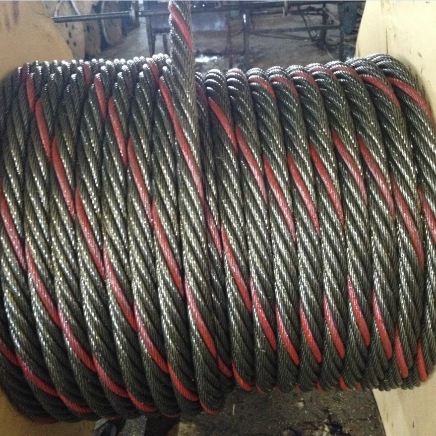
Wire rope forms an important part of many machines and structures. It is comprised of continuous wire strands wound around a central core. There are many kinds of wire rope designed for different applications. Most of them are steel wires made into strands wound with each other. The core can be made of steel, rope or even plastics.
Wire ropes (cables) are identified by several parameters including size, grade of steel used, whether or not it is preformed, by its lay, the number of strands and the number of wires in each strand.
A typical strand and wire designation is 6x19. This denotes a rope made up of six strands with 19 wires in each strand. Different strand sizes and arrangements allow for varying degrees of rope flexibility and resistance to crushing and abrasion. Small wires are better suited to being bent sharply over small sheaves (pulleys). Large outer wires are preferred when the cable will be rubbed or dragged through abrasives.
There are three types of cores. An independent wire rope core (IWRC) is normally a 6x7 wire rope with a 1x7 wire strand core resulting in a 7x7 wire rope. IWRCs have a higher tensile and bending breaking strength than a fiber core rope and a high resistance to crushing and deformation.
A wire strand core (WSC) rope has a single wire strand as its core instead of a multistrand wire rope core. WSC ropes are high strength and are mostly used as static or standing ropes.
Wire ropes also have fiber cores. Fiber core ropes were traditionally made with sisal rope, but may also use plastic materials. The fiber core ropes have less strength than steel core ropes. Fiber core ropes are quite flexible and are used in many overhead crane applications.
The lay of a wire rope is the direction that the wire strands and the strands in the cable twist. There are four common lays: right lay, left lay, regular lay and lang lay. In a right lay rope the strands twist to the right as it winds away from the observer. A left lay twists to the left. A regular lay rope has the wires in the strands twisted in the opposite direction from the strands of the cable. In a lang lay rope, the twist of the strands and the wires in the strands are both twisted the same way. Lang lay ropes are said to have better fatigue resistance due to the flatter exposure of the wires.
Wire ropes are made mostly from high carbon steel for strength, versatility, resilience and availability and for cost consideration. Wire ropes can be uncoated or galvanized. Several grades of steel are used and are described in Table 1.
Steel cable wire is stiff and springy. In nonpreformed rope construction, broken or cut wires will straighten and stick out of the rope as a burr, posing a safety hazard. A preformed cable is made of wires that are shaped so that they lie naturally in their position in the strand, preventing the wires from protruding and potentially causing injury. Preformed wire ropes also have better fatigue resistance than nonpreformed ropes and are ideal for working over small sheaves and around sharp angles.
Lubricating wire ropes is a difficult proposition, regardless of the construction and composition. Ropes with fiber cores are somewhat easier to lubricate than those made exclusively from steel materials. For this reason, it is important to carefully consider the issue of field relubrication when selecting rope for an application.
There are two types of wire rope lubricants, penetrating and coating. Penetrating lubricants contain a petroleum solvent that carries the lubricant into the core of the wire rope then evaporates, leaving behind a heavy lubricating film to protect and lubricate each strand (Figure 2). Coating lubricants penetrate slightly, sealing the outside of the cable from moisture and reducing wear and fretting corrosion from contact with external bodies.
Both types of wire rope lubricants are used. But because most wire ropes fail from the inside, it is important to make sure that the center core receives sufficient lubricant. A combination approach in which a penetrating lubricant is used to saturate the core, followed with a coating to seal and protect the outer surface, is recommended. Wire rope lubricants can be petrolatum, asphaltic, grease, petroleum oils or vegetable oil-based (Figure 3).
Petrolatum compounds, with the proper additives, provide excellent corrosion and water resistance. In addition, petrolatum compounds are translucent, allowing the technician to perform visible inspection. Petrolatum lubricants can drip off at higher temperatures but maintain their consistency well under cold temperature conditions.
Various types of greases are used for wire rope lubrication. These are the coating types that penetrate partially but usually do not saturate the rope core. Common grease thickeners include sodium, lithium, lithium complex and aluminum complex soaps. Greases used for this application generally have a soft semifluid consistency. They coat and achieve partial penetration if applied with pressure lubricators.
Petroleum and vegetable oils penetrate best and are the easiest to apply because proper additive design of these penetrating types gives them excellent wear and corrosion resistance. The fluid property of oil type lubricants helps to wash the rope to remove abrasive external contaminants.
Wire ropes are lubricated during the manufacturing process. If the rope has a fiber core center, the fiber will be lubricated with a mineral oil or petrolatum type lubricant. The core will absorb the lubricant and function as a reservoir for prolonged lubrication while in service.
If the rope has a steel core, the lubricant (both oil and grease type) is pumped in a stream just ahead of the die that twists the wires into a strand. This allows complete coverage of all wires.
After the cable is put into service, relubrication is required due to loss of the original lubricant from loading, bending and stretching of the cable. The fiber core cables dry out over time due to heat from evaporation, and often absorb moisture. Field relubrication is necessary to minimize corrosion, protect and preserve the rope core and wires, and thus extend the service life of the wire rope.
If a cable is dirty or has accumulated layers of hardened lubricant or other contaminants, it must be cleaned with a wire brush and petroleum solvent, compressed air or steam cleaner before relubrication. The wire rope must then be dried and lubricated immediately to prevent rusting. Field lubricants can be applied by spray, brush, dip, drip or pressure boot. Lubricants are best applied at a drum or sheave where the rope strands have a tendency to separate slightly due to bending to facilitate maximum penetration to the core. If a pressure boot application is used, the lubricant is applied to the rope under slight tension in a straight condition. Excessive lubricant application should be avoided to prevent safety hazards.
Some key performance attributes to look for in a wire rope lubricant are wear resistance and corrosion prevention. Some useful performance benchmarks include high four-ball EP test values, such as a weld point (ASTM D2783) of above 350 kg and a load wear index of above 50. For corrosion protection, look for wire rope lubricants with salt spray (ASTM B117) resistance values above 60 hours and humidity cabinet (ASTM D1748) values of more than 60 days. Most manufacturers provide this type of data on product data sheets.
Cable life cycle and performance are influenced by several factors, including type of operation, care and environment. Cables can be damaged by worn sheaves, improper winding and splicing practices, and improper storage. High stress loading, shock loading, jerking heavy loads or rapid acceleration or deceleration (speed of the cable stopping and starting) will accelerate the wear rate.
Corrosion can cause shortened rope life due to metal loss, pitting and stress risers from pitting. If a machine is to be shut down for an extended period, the cables should be removed, cleaned, lubricated and properly stored. In service, corrosion and oxidation are caused by fumes, acids, salt brines, sulfur, gases, salt air, humidity and are accelerated by elevated temperatures. Proper and adequate lubricant application in the field can reduce corrosive attack of the cable.
Abrasive wear occurs on the inside and outside of wire ropes. Individual strands inside the rope move and rub against one another during normal operation, creating internal two-body abrasive wear. The outside of the cable accumulates dirt and contaminants from sheaves and drums. This causes three-body abrasive wear, which erodes the outer wires and strands. Abrasive wear usually reduces rope diameter and can result in core failure and internal wire breakage. Penetrating wire rope lubricants reduce abrasive wear inside the rope and also wash off the external surfaces to remove contaminants and dirt.
Many types of machines and structures use wire ropes, including draglines, cranes, elevators, shovels, drilling rigs, suspension bridges and cable-stayed towers. Each application has specific needs for the type and size of wire rope required. All wire ropes, regardless of the application, will perform at a higher level, last longer and provide greater user benefits when properly maintained.
Lubrication Engineers, Inc. has found through years of field experience, that longer wire rope life can be obtained through the use of penetrating lubricants, either alone or when used in conjunction with a coating lubricant. Practical experience at a South African mine suggests that life cycles may be doubled with this approach. At one mine site, the replacement rate for four 44-mm ropes was extended from an average 18.5 months to 43 months. At another mine, life cycles of four 43-mm x 2073 meter ropes were extended from an average 8 months to 12 months.
In another study involving 5-ton and 10-ton overhead cranes in the United States that used 3/8-inch and 5/8-inch diameter ropes, the average life of the ropes was doubled. The authors attribute this increased performance to the ability of the penetrating lubricant to displace water and contaminants while replacing them with oil, which reduces the wear and corrosion occurring throughout the rope. A good spray with penetrating wire rope lubricant effectively acts as an oil change for wire ropes.
In these examples, the savings in wire rope replacement costs (downtime, labor and capital costs) were substantial and dwarfed the cost of the lubricants. Companies who have realized the importance of proper wire rope lubrication have gained a huge advantage over those who purchase the lowest priced lubricant, or no lubricant at all, while replacing ropes on a much more frequent basis.
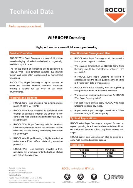
A tenacious, semi-fluid, non-melting grease designed for complete lubrication and corrosion protection on most types of wire ropes, particularly in hostile conditions.
ROCOL® Wire Rope Dressing is highly resistant to water and provides excellent corrosion protection making it suitable for use in salt water environments even under water.

Construction The size and number of wires in each strand, as well as the size and number of strands in the rope greatly affect the characteristics of the rope. In general, a large number of small-size wires and strands produce a flexible rope with good resistance to bending fatigue. The rope construction is also important for tensile load (static, live or shock) abrasive wear, crushing, corrosion and rotation. The number of strands and wires will influence the flexibility, fatigue and wear resistance of any given wire rope. Rope selection is often a compromise. Generally the more load bearing wires in the rope the greater the flexibility, however the smaller the wires the less abrasion resistance. For example, the same nominal diameter 7 x 7 wire would be less flexible than a 7 x 19 wire, hence a large number of small size wire and strands produce a flexible rope with good resistance to bending fatigue wear. The construction of wire rope is defined by the number of outer strands (first number), and the number of wires within that strand (second number) and then by the arrangement of the wires in each strand (shown in brackets). The wires in each strand can be arranged in several ways, for example a 6 x 19 construction the 19 wires in each strand are laid 9 around 9 around 1 centre wire.
Endurance Dyform 6 20-22// Usha Martin Crane Wire Rope 23-25// Wire Rope Slings Overview 26 // Tri-flex Wire Rope Slings 27 // Wire Rope Terminations 27 //
Core The core of a steel wire rope serves as a foundation for the strands, providing stability by keeping them in place throughout the life of the rope. Wire ropes can be supplied with either a fibre or wire core. Grade Wire rope can be manufactured in different steel grades, which directly affects the Minimum Breaking Force, (MBF). The higher the grade the higher the MBF. Common wire grades include: 1570, 1770, 1960 and 2070 Finish Wire Ropes can be supplied as Black (self-colour), Galvanised or Stainless Steel. Wire rope is lubricated at the time of manufacture, to help reduce friction between wires and strands, and the friction between the rope and drum or sheave. In addition, the lubrication retards corrosion and inhibits possible rotting of the fibre core.
RHOL Right Hand Ordinary Lay LHOL Left Hand Ordinary Lay RHLL Right Hand Lang’s Lay LHLL Left Hand Lang’s Lay Pref Preformed Post Postformed WRC Wire Rope Core WSC Wire Strand Core FC Fibre Core FW Filler Wire Strand Construction D or d Diameter (in millimetres)
Rotating or Non-Rotating Rotation resistant wire ropes are manufactured to resist rotation under load and are suitable for crane use and where long lengths are required.
Clamping Wire Rope To ensure complete safety, it is imperative that wire ropes are clamped correctly. The diagrams below are a guide only. Please refer to the relevant Australian Standards AS 2076 for further information.
Correct Spooling of Steel Wire Rope on Drum It is imperative to correctly spool wire rope onto a drum. Improper spooling induces torque within the rope, which in turn reduces the life of the rope.
tension to avoid any slack on inner layers that can be crushed or nicked against the groove walls by outer layers. In general, the tighter the line, the better the spooling, but the rope should be tensioned with at least 2% of the breaking load or 10% of the working load.
Lubricating Steel Wire Ropes All steel wire ropes supplied by Robertsons are lubricated at the time of manufacture, however, periodic lubrication with good quality acid free and moisture free lubricant during use is required to ensure best performance. The following are accepted ways to lubricate wire ropes during use.
Steel Wire Rope Cutting Procedure Hand cutters for cutting ropes up to 8mm in diameter are sufficient. Mechanical or hydraulic cutters will be required for wire ropes with larger diameters.
Careless cutting can result in the balance of tension in the rope being destroyed. In every case, each side of the cut must be correctly seized to prevent strand
C: Both ends of the seizing wire are then pulled tight and twisted together for a length of one rope diameter. The twisted connection is then hammered into a strand valley.
Typical Steel Wire Rope Failures Steel wire rope is tough and durable, however eventually it will reach the end of its safe service life. Below are some examples of typical damage and deterioration. Steel wire ropes should be inspected every 12 months.
Storing Steel Wire Ropes Ensure steel wire rope is stored in a weather-proof storage space. If wire rope is to be kept unused for a considerable amount of time, it must be protected from the elements. The ideal storage area is a dry, well-ventilated building or shed. Avoid closed, unheated, tightly sealed buildings or enclosures because condensation will form when warm, moist outside (ambient) air envelopes the colder rope. Although wire rope is protected by a lubricant, this is not totally effective since condensation can still occur within the small sections between strands and wires, thereby causing corrosion problems. Ensure the reels are kept up off the ground, or are placed on a concrete floor. • Reels should be mounted on jacks or placed on a swift (with a brake arrangement) and care taken to see that the reel rotates as the rope unwinds • Ensure clearance for free rotation of the reel when the rope end is pulled and maintain continuous tension during haul off Correct Handling of Steel Wire Ropes Incorrect handling of steel wire ropes can cause kinking or loops Ropes should be stored in a clean dry place under cover. Reels or coils should be kept off the ground and supported by timber. They should also be examined periodically and rope dressing renewed as required. 1) Unreeling and Uncoiling Reels should be mounted on jacks and care taken to see that the reel rotates as the rope unwinds. Timber should be applied as a lever to one of the flanges to act as a brake, keeping the rope tight and preventing the reel from over- running. When the ropes are supplied in coils a turntalbe or swift should be employed and the free end pulled out with event tension as the swift, or turnatable revolve. Over-winding should be avoided at all times to obviate kinking. Coils may also be unwound by securing the free outside end of the rope and then rolling the coil along the ground; care being taken at all times to ensure that the coil is held firmly together, avoiding tight coils or kinks. Ropes should be stored in a clean dry place under cover. Reels or coils should be kept off the ground and supported by timber. They should also be examined periodically and rope dressing r newed as required. 1) Unreeling and Uncoiling Reels should be mounted on jacks and care taken to see that th reel ro ates as the rope unwinds. Timber should be applied as a lever t one of the flanges to act as a brake, keeping the rope tight and pr ve ting the reel from over- run ing. When the ropes are supplied in coils a turntalbe or swift should b employed and the fre end pulled out with vent tension as the swift, or turnatable revolve. Over-winding should be avoided t all times to obviate kinking. Coils may also be unwound by securing the free outside end of the rope and then rolling the coi along the ground; care being taken t all times to ensure that the coil is held firmly together, avoiding tight coils or kinks. Ropes should be stored in a clean ry lace under cove . R ls or coils shoul be k pt off the ground and supported by timber. They should also be examined periodically and rope dressing renewed as required. 1) Unreeling and Unc iling Re s should be mounted on jacks and c re taken to se that the reel r tates as the rope u winds. Timbe should be appl ed as a lever to one of the flanges to act as a brake, keeping the rope tight and preventing the reel from over- running. When the rope are supplied in coils a turntalbe or swift employed and the free end pulled out w th event tension as the swift, or tur atabl rev lve. Ov r-winding shoul be av ided at all t mes to obviate kinking. Coils may also be unwound by sec ing the fr e out id end of th rope and the rolling the c il along the ground; care being taken at all times to ensure that the coil is held firmly together, avoiding tight coils or kinks. Ropes should be stored in a clean dry place under cover. Reels or coils should be kept off the ground and supported by timber. They should also be examined periodically and rope dressing renewed a required. 1) Unreeling and Uncoiling Reels should be mounted on jacks and care taken to see that the reel rotates as the rope unwinds. Timber should be applied as a lever to one of the flanges to act as a brake, keeping the rope tight and preventing the reel from over- running. When the ropes are supplied in coils a turntalbe or swift should be employed and the free end pulled out with event tension as the swift, or turnatable revolve. Over-winding should be avoided at all times to obviate kinking. Coils may also be unwound by securing the free outside end of the rope and then rolling the coil along the ground; care being taken at all times to ensure that the coil is held firmly together, avoiding tight coils or kinks. Ropes should be stored in a clean dry place under cove . R els or coils should be k pt off the ground and supported by timber. They should also be xamined p riodically and rope dressing renewed as required. 1) Unreeling and U c iling Reels should be mounted on jacks and care taken to see that the reel tates as the rope u winds. Timb r should be appl ed as a lev r to ne of the flanges to act as a brake, keeping the rope tight and prev nti g the reel from over- running. When the rope are supplied in coils a turntalbe or swift empl y d and the free end pull d out with event tensi n as the swift, or t r at ble rev lve. Ov r-winding sh uld be avoided at all times to bviate kinki g. Coils may also be unwound by securing the free out id nd of the rop and then rollin the coil a ong the ground; care being taken at ll times to ensure that the coil is held firmly together, avoiding tight coils or kinks. forming in the steel wire rope, causing permanent damage. Below is a summary of the correct way to handle steel wire rope:
Although the steel wire rope is lubricated at the time of manufacture, a suitable lubricant should be applied every three months. The reels containing the steel wire ropes should also be rotated 90 degrees every three months.
11. Handling and Care of Wire Ropes 1. Handling and Care of Wire Ropes 11. Handling and Care of Wire Ropes 11. Handling and Care of Wire Ropes 1 . Handling and Care of Wire Rop s
2) Seizings It is important that before cutting ropes are properly seized with annealed mild steel wire or strand to avoid slack wires and possible rope distortion. 2) Se zings It s important that before cutting ropes are properly s ized with annealed mild steel wire or strand to avoid slack wires and possible rope distortion. 2) Seizings It is important that bef re cutting ropes are properly seized with annealed mild steel wire or strand to avoid slack wires and possible rope distortion. 2) Seizings It is important that before cutting ropes are properly seized with annealed mild steel wire or strand to avoid slack wires and possible rope distortion. 2) Seiz ngs It is important that before cutting ropes are properly seized with annealed mild steel wire or strand to avoid slack wires and possible rope distortion.
Wire Rope Terminations Hand spliced or machine swaged slings, with your choice of terminations, can be manufactured and tested (if required) on our premises at short notice. All slings and assemblies are permanently marked with safe working loads, based on a 5:1 factor of safety. Machine Swaging Aluminium Ferrules Sizes 2mm – 52mm. Copper Ferrules Sizes 2mm – 10mm Steel Ferrules Sizes 9mm – 75mm Swage Sockets Sizes 3mm – 52mm Hand Splicing from 2mm – 75mm dia
Galvanised Wire RHOL 63 41.8 Galvanised Wire RHOL 90 60.2 Galvanised Wire RHOL 107 70.7 Galvanised Wire RHOL 124 82 Galvanised Wire RHOL 161 107 Galvanised Wire RHOL 204 135 Galvanised Wire RHOL 252 167 Galvanised Wire RHOL 304 202 Galvanised Wire RHOL 363 241 Galvanised Wire RHOL 426 283 Galvanised Wire RHOL 493 328 Galvanised Wire RHOL 644 428 Galvanised Wire RHOL 816 542 Galvanised Wire RHOL 911 604 Galvanised Wire RHOL 1009 669 Galvanised Wire RHOL 1220 810 Galvanised Wire RHOL 1700 1110
Galvanised Wire RHOL 18.9 10.4 Galvanised Wire RHOL 27.2 14.3 Galvanised Wire RHOL 37.2 20.2 Galvanised Wire RHOL 47.5 25.66 Galvanised Wire RHOL 59.3 32 Galvanised Wire RHOL 73 39.4
POWERFORM® 8/8P • A high strength eight strand rope with plastic impregnated core ideal for situations where longer service life is required • High fatigue life resulting from the unique compaction process • Maximum resistance to crushing. Recommended for multi-layer spooling operations
• A sample of rope from each production batch is tested to destruction • Greater surface contact area resulting from the eight strand construction and compacted finish give longer rope life and reduced sheave wear • Optional plastic impregnation of the steel core. (P) signifies full plastic impregnation of the steel core.
POWERFORM® 35/35P • Superior strength and resistance to rotation • Suitable for use on single part and multi-part hoist reeving systems • High fatigue life due to unique compaction process • A sample of rope from each production batch is tested to destruction
52 2256.0 230.0 *Mass per unit length of POWERFORM 35P increases by approx. 3%. Note: • POWERFORM 35P is available on special request and prior confirmation. • Rope sizes and Breaking Force not shown in the standard table, may be available on request and prior confirmation.
Note: • POWERFORM 8P is available for rope diameter 16mm and above on special request and prior confirmation. • Rope sizes and Breaking Force not shown in the standard table, may be available on request and prior confirmation.
POWERFORM® 6/6P • A high strength rugged six strand rope ideal for situations where longer service life is required • Can be substituted for any six strand construction to improve service life • High fatigue life due to unique compaction process • A sample of rope from each production batch is tested to destruction
Typical Steel Wire Rope Sling Description Hand spliced or machine swaged slings, with your choice of terminations, can be manufactured and tested (if required) on our premises at short notice. All slings and assemblies are permanently marked with safe working loads, based on a 5:1 factor of safety.
*Mass per unit length of POWERFORM 6P increases by approx. 3%. Note: • POWERFORM 6P is available only for 16mm and above on special request and prior confirmation. • Rope sizes and Breaking Force not shown in the standard table, may be available on request and prior confirmation.
Part One in this series appeared in our June issue and dealt with early and more recent investigations which have proved the importance of wire rope lubrication. Part Two (July issue) covered the duties and properties of wire rope lubricants.

The following instructions and warnings combine to provide guidance on product safety and are intended for use by those already having a working knowledge of wire ropes, as well as the new user. They should be read, followed and passed on to others.
Ensure that the correct type of wire rope is selected for the equipment by referring to the OEM’s instruction manual or other relevant documents. If in doubt, contact Bridon for guidance.
By applying the relevant design factor and, where applicable, the efficiency of the rope termination, the required minimum breaking load or force of the rope will be determined, the values of which are available from the relevant National or International standards or from specific Product Data literature. If in doubt, ask for advice from Bridon.
Wire rope which bends around sheaves, rollers or drums will deteriorate through ‘bending fatigue’. Reverse bending and high speed will accelerate theprocess. Therefore, under such conditions select a rope with high bending fatigue resistance. Refer to Product Data Information, and if in doubt, ask for advice.
Abrasion weakens the rope by removing metal from both the inner and outer wires. Therefore, a rope with large outer wires should normally be selected.
Rope with a large number of small wires is more susceptible to corrosion than rope with a small number of large wires. Therefore, if corrosion is expected to have a significant effect on rope performance. The rope may have to be lubricated frequently in service or a galvanized rope may be selected.
‘Cabling’ of rope reeving due to block rotation can occur if the rope is incorrectly selected. Applications involving high lifts are particularly vulnerable to this condition, therefore, ropes specifically designed to resist rotation need to be selected.
Ropes which have high rotation characteristics must not be selected unless both ends of the rope are fixed or the load is guided and unable to rotate.
Ropes In the event that it is necessary to connect one rope to another (in series), it is essential that they have the required strength, are of the same type and both have the same lay direction (i.e. connect ‘right’ lay to ‘right’ lay).
Rope length and/or difference in length between two or more ropes used in a set may be a critical factor and must be considered along with rope selection.
Wire rope will elongate under load. Other factors, such as temperature, rope rotation and internal wear, will also have an effect. These factors should also be considered during rope selection.
Single layer round strand rope is normally supplied preformed. However, if a non-preformed rope is selected then personnel responsible for its installation and/or maintenance need to take particular care when handling such rope, especially when cutting.
Wire rope with a steel core should be selected if there is any evidence to suggest that a fiber core will not provide adequate support to the outer strands and/or if the temperature of the working environment may be expected to exceed 180°F.
For operating temperatures above 200°F, de-rating of the minimum breaking force of the rope is necessary (e.g. between 200°F and 400°F reduce by 10%; between 400°F and 600°F reduce by 25%; between 600°F and 800°F reduce by 35%).
Certain types of rope end terminations also have limiting operating temperatures and the manufacturer or Bridon should be consulted where there is any doubt. Ropes with aluminum ferrules must not be used at temperatures in excess of 300°F.
Unwrap the rope and examine the rope immediately after delivery to check its identification and condition and verify that it is in accordancewith the details on the Certificates and/or other relevant documents.
Check the rope diameter and examine any rope terminations to ensure that they are compatible with the equipment or machinery to which they are to be fitted.
Never store wire rope in areas subject to elevated temperatures as this may seriously affect its future performance. In extreme cases, its original as-manufactured strength may be severely reduced rendering it unfit for safe use.
Failure to do so may result in the rope becoming contaminated with foreign matter and start the onset of corrosion before the rope is even put to work.
Support the reel on a simple A-frame or cradle located on ground, which is capable of supporting the total mass of rope and reel. Ensure that the rope is stored where it is not likely to be affected by chemical fumes, steam or other corrosive agents.
Examine ropes in storage periodically and, when necessary, apply a suitable dressing which is compatible with the manufacturing lubricant. Contact the rope supplier, Bridon or original equipment manufacturer’s (OEM) manual for guidance on types of dressings available, methods of application and equipment for the various types of ropes and applications.
Ensure that the rope is stored and protected in such a manner that it will not be exposed to any accidental damage either during the storage period or when placing the rope in or taking it out of storage.
Failure to carry out or pay attention to any of the above could result in a loss of strength and/or a reduction in performance. In extreme cases, the rope may be unfit for safe use.
Failure to wear suitable protective clothing and equipment may result in skin problems from over exposure to certain types of rope lubricants and dressings; burns from sparks, rope ends, molten lubricants and metals when cutting ropes or preparing sockets for re-use; respiratory or other internal problems from the inhalation of fumes when cutting ropes or preparing sockets for re-use; eye injuries from sparks when cutting ropes; lacerations to the body from wire and rope ends; bruising of the body and damage to limbs due to rope recoil, backlash and any sudden deviation from the line of path of rope.
Ensure that the correct rope has been supplied by checking to see that the description on the Certificate is in accordance with that specified in the purchaser’s order.
For verification purposes, measure the diameter by using a suitable rope vernier fitted with jaws broad enough to cover not less than two adjacent strands. Take two sets of measurements spaced at least 3′ apart, ensuring that they are taken at the largest cross-sectional dimension of the rope. At each point, take measurements at right angles to each other
Examine the rope visually to ensure that no damage or obvious signs of deterioration have taken place during storage or transportation to the installation site.
Note:Grooves must have clearance for the rope and provide adequate circumferential support to allow for free movement of the strands and facilitate bending. When grooves become worn and the rope is pinched at the sides, strand and wire movement is restricted and the ability of the rope to bend is reduced.
When a new rope is fitted, a variation in size compared with the old worn rope will be apparent. The new rope may not fit correctly into the previously worn groove profile and unnecessary wear and rope distortion is likely to occur. This may be remedied by machining out the grooves before the new rope is installed. Before carrying out such action, the sheaves or drum should be examined to ensure that there will be sufficient strength remaining in the underlying material to safely support the rope.
If the coil is too large to physically handle it may be placed on a ‘swift’ turntable and the outside end of the rope pulled out allowing the coil to rotate.
Never pull a rope away from a stationary coil as this will induce turn into the rope and kinks will form. These will adversely affect rope performance.
Pass a shaft through the reel and place the reel in a suitable stand, which allows it to rotate and be braked to avoid overrun during installation. Where multi-layer coiling is involved, it may be necessary for the reel to be placed in equipment which has the capability of providing a back tension in the rope as it is being transferred from reel to drum. This is to ensure that the underlying (and subsequent) laps are wound tightly on the drum.
A kink can severely affect the strength of a six strand rope and can result in distortion of a Rotation Resistant rope leading to its immediate discard.
Ensure that the reel stand is mounted so as not to create a reverse bend during reeving (i.e. for a winch drum with an overlap rope, take the rope off the top of the reel).
Ensure that any equipment or machinery to be roped is correctly and safely positioned and isolated from normal usage before installation commences. Refer to the OEM’s instruction manual and the relevant ‘Code of Practice’.
When releasing the outboard end of the rope from a reel or coil, ensure that this is done in a controlled manner. On release of the bindings and servings used for packaging, the rope will want to straighten itself from its previously bent position. Unless controlled, this could be a violent action. Stand clear.
If installing the new rope with the aid of an old one, one method is to fit a wire rope sock (or stocking) to each of the rope ends. Always ensure that the open end of the sock (or stocking) is securely attached to the rope by a serving or alternatively by a clip. Connect the two ends via a length of fiber rope of adequate strength in order to avoid turn being transmitted from the old rope into the new rope. Alternatively, a length of fiber or steel rope of adequate strength may be reeved into the system for use as a pilot / messenger line. Do not use a swivel during the installation of the rope.
Monitor the rope carefully as it is being pulled into the system and make sure that it is not obstructed by any part of the structure or mechanism which may cause the rope to come free.
Take particular care and note the manufacturer’s instructions when the rope is required to be cut. Apply secure servings on both sides of the cut mark.
Ensure that the length of serving is at least equal to two rope diameters. (Note:Special servings are required for spiral ropes, i.e. spiral strand and locked coil.)
One serving either side of the cut is normally sufficient for preformed ropes. For non-preformed ropes, (i.e. Rotation Resistant ropes) a minimum of two servings each side of the cut will be necessary.
Arrange and position the rope in such a manner that at the completion of the cutting operation the rope ends will remain in position, thus avoiding any backlash or any other undesirable movement.
Cut the rope with a high speed abrasive disc cutter. Other suitable mechanical or hydraulic shearing equipment may be used although not recommended when a rope end is required to be welded or brazed.
Ensure adequate ventilation to avoid any build-up of fumes from the rope and its constituent parts including any fiber core (natural or synthetic) any rope lubricant(s) and any synthetic filling and/or covering material.
Rope produced from carbon steel wires in the form shipped is not considered a health hazard. During subsequent processing (e.g. cutting, welding, grinding, cleaning), dust and fumes may be produced which contain elements which may affect exposed workers.
The products used in the manufacture of steel wire ropes for lubrication and protection present minimal hazard to the user in the form shipped. The user must however, take reasonable care to minimize skin and eye contact and also avoid breathing their vapor and mist.
When terminating a rope end with a wedge socket, ensure that the rope tail cannot withdraw through the socket by securing a clamp to the tail or by following the manufacturer’s instructions. The tail length should be a minimum of 20 rope diameters for all Rotation Resistant wire rope and a minimum of 6 rope diameters for 6 and 8 strand ropes.
The loop back method uses a rope grip and the loop should be lashed to the live part of rope by a soft wire serving or tape to prevent flexing of the rope in service.
When coiling a rope on a plain (or smooth) barrel drum, ensure that each lap lies tightly against the preceding lap. The application of tension in the rope greatly assists in the coiling of the rope.
The direction of coiling of the rope on the drum is important, particularly when using plain barrel drums, and should be related to the direction of lay of the rope in order to induce close coiling.
When multi-layer spooling has to be used it should be realized that after the first layer is wound on a drum, the rope has to cross the underlying rope in order to advance across the drum in the second layer. The points at which the turns in the upper layer cross those of the lower layer are known as the cross-over points and the rope in these areas is susceptible to increased abrasion and crushing. Care should be taken when installing a rope on a drum and when operating a machine to ensure that the rope is spooled and layered correctly.
Check the state of re-usable rope end terminations for size, strength, defects and cleanliness before use. Nondestructive testing may be required depending on the material and circumstances of use. Ensure that the termination is fitted in accordance with the OEM’s instruction manual or manufacturer’s instructions. When re-using a socket and depending on its type and dimensions, the existing cone should be pressed out. Otherwise, heat may be necessary.
‘Run in’ the new rope by operating the equipment slowly, preferably with a low load, for several cycles. This permits the new rope to adjust itself gradually to working conditions.
Note:Unless otherwise required by a certifying authority, the rope should be in this condition before any proof test of the equipment or machinery is carried out.
If samples are required to be taken from the rope for subsequent testing and/or evaluation, it is essential that the condition of the rope is not disturbed. Refer to the instructions given in 4.12 and, depending on the rope type and construction, any other special manufacturer’s instructions.
Inspect the rope and related equipment at the beginning of every work period at least daily in most instances and particularly following any incident which could have damaged the rope or installation.
The entire length of rope should be inspected and particular attention paid to those sections that experience has proven to be the main areas of deterioration. Excessive wear, broken wires, distortion and corrosion are the usual signs of deterioration. For a more detailed examination, special tools are necessary, which will also facilitate internal inspection.
In the case of ropes working over drums or sheaves, it is particularly necessary to examine those areas entering or leaving the grooves when maximum loads (i.e. shock loads) are experienced, or those areas which remain for long periods in exposed places, such as over a jib head sheave.
On some running ropes, but particularly relevant to standing ropes (e.g. pendant ropes), the areas adjacent to terminations should be given special attention by rope diameter measurements and visual examination for broken wires and corrosion.
Note:Shortening the rope repositions the areas of maximum deterioration in the system. Where conditions permit, begin operating with a rope which has a slightly longer length than necessary in order to allow for periodic shortening.
When a non-preformed rope or multi-layer rope is used with a wedge socket and is required to be shortened, it is essential that the end of the rope is secured by welding or brazing before the rope is pulled through the main body of the socket to its new position.
Slacken the wedge in the socket. Pass the rope through the socket by an amount equivalent to the crop length or sample required. Note that the original bent portion of the rope must not be retained within the wedge socket. Replace the wedge and pull up the socket. Prepare and cut in accordance with section 4.12. Ensure that the rope tail cannot withdraw through the socket, see section 4.13.
Failure to observe this instruction will result in a significant deterioration in the performance of the rope and could render the rope completely unfit for further service.
In cases where severe rope wear takes place at one end of a wire rope, the life of the rope may be extended by changing round the drum end with the load end, i.e. turning the rope ‘end for end’ before deterioration becomes excessive.
Remove broken wires as they occur by bending backwards and forwards using a pair of pliers until they break deep in the valley between two outer strands. Wear protective clothing, such as overalls, industrial gloves, helmet, eye protectors and safety footwear during this operation.
Do not shear off the ends of broken wires with pliers as this will leave an exposed jagged edge, which is likely to damage other wires in the rope and lead to premature removal of the rope from service. Failure to wear adequate protective clothing could result in injury.
Note:Broken wires are a normal feature of service, more so towards the end of the rope’s life, resulting from bending fatigue and wear. The local break up of wires may indicate some mechanical fault in the equipment.
Do not operate an appliance if for any reason (e.g. rope diameter, certified breaking force, rope construction, length or strength and type of rope termination) the wire rope and its termination is considered unsuitable for the required duty.
Do not operate an appliance if the wire rope fitted has become distorted, been damaged or has deteriorated to a level such that discard criteria has been reached or is likely to be reached prior to normal expected life based on historical performance data.
Do not carry out any inspection, examination, dressing / lubrication, adjustment or any other maintenance of the rope while it is suspending a load, unless otherwise stated in the OEM’s instruction manual or other relevant documents.
Do not carry out any inspection or maintenance of the rope if the appliance controls are unattended unless the surrounding area has been isolated or sufficient warning signs have been posted within the immediate vicinity. If the appliance controls are attended, the authorized person must be able to communicate effectively with the driver or controller of the appliance during the inspection process.
The use of cleaning fluids (particularly solvent based) is likely to ‘cut back’ the existing rope lubricant leading to a greater quantity of lubricant accumulating on the surface of the rope. This may create a hazard in appliances and machinery which rely on friction between the rope and the drive sheave (e.g. elevators, friction winders and ski lifts).
Lubricants selected for in-service dressing must be compatible with the rope manufacturing lubricant and should be referenced in the OEM’s instruction manual or other documents approved by the owner of the appliance. If in doubt, contact Bridon.
Take particular care when applying any in-service lubricant / dressing. Application systems which involve pressure should only be operated by trained and authorized persons and the operation carried out strictly in accordance with the manufacturer’s instructions.
Note:The authorized person carrying out a rope inspection must be capable of recognizing the potential loss of safe performance of such a rope in comparison with lubricated rope.
The authorized person responsible for carrying out wire rope maintenance must ensure that the ends of the rope are secure. At the drum end, this will involve checking the integrity of the anchorage and ensuring that there are at least three dead wraps tightly spooled.
Damage to, or removal of, component parts (mechanical or structural) caused by abnormal contact with wire rope can be hazardous to the safety of the appliance and/or the performance of the rope (e.g. damage to the drum grooving such that spooling is erratic and/or the rope is ‘pulled down’ into underlying layers, which might cause a dangerous condition or, alternatively, cause localized rope damage at ‘cross-over’ positions, which might then radically affect performance; loss / removal of wear plates protecting the structure leading to major structural damage by cutting and/or failure of the wire rope due to mechanical severance).
Following any periodic examination or routine or special inspection where any corrective action is taken the Certificate should be updated and a record made of the defects found, the extent of the changes and the condition of the rope.
Apply the following procedures for the selection and preparation of samples, from new and used lengths of rope, for the purpose of examination and testing to destruction.
Check that the rope end, from which the sample will be taken, is secured by welding or brazing. If not, select the sample length further away from the rope end and prepare new servings.
Handle the rope in accordance with the instructions given in Section 4. Serve the rope using the buried wire technique and apply a rope clamp or grip as close to the cut mark as practically possible. Do not use solder to secure the servings.
The rope should be cut with a high speed abrasive disc cutter or an oxyacetylene torch. Weld the rope ends of the sample as described in section 4.12, after which the clamp or grip can be removed.
The identification of the rope must be established and the sample suitably marked and packed. It is recommended that the 10′ sample is retained straight and secured to a wood pallet for transportation.
Failure to comply with these procedures will result in measured breaking force values which are not truly representative of the actual strength of the rope.
Note:The authorized competent person should also be familiar with the latest versions of ANSI, ASME or ISO Standards. Other standards and instructions covering rope discard may also be applicable. In the case of synthetic sheaves (or synthetic linings), refer to the OEM’s instruction manual or contact the sheave (or lining) manufacturer for specific discard criteria.
If a wire rope is removed from service at a level of performance substantially different to historically established performance data and without any obvious reason(s), contact Bridon for further guidance.
Only qualified and experienced personnel, taking the appropriate safety precautions and wearing the appropriate protective clothing, should be responsible for removing the wire rope.
Store discarded rope in a safe and secure location or compound and ensure that it is suitably marked to identify it as rope which has been removed from service and not to be used again.
Discarded rope can be a danger (e.g. protruding broken wires, excessive grease / lubricant and rope mass) to personnel and equipment if not handled correctly and safely during disposal.

Information about wire rope unloading, storage, handling, installation, operation, lubrication, inspection, maintenance and possible causes for rope faults is given in this article to get best service from it.
Whenever handling wire rope, take care not to drop reels or coils. This can damage wire rope and collapse the reel, making removal of the wire rope extremely difficult. Rope in a coil is unprotected and may be seriously damaged by dropping.
Wire ropes should be stored in a well ventilated, dry building or shed and shall not be in contact with the floor. If it is necessary to store them outside, cover them so that moisture cannot induce corrosion. The place should be free from dust, moisture and chemical fumes. To protect the wooden reels from the attack of termites, the floor should be cemented. Turning the reel occasionally, about half a turn, helps prevent migration of the rope lubricant. If ropes are to be stored for long time, it is advisable to examine them periodically and to apply dressing of lubricant to the top layer of rope on the drum.
Care must be taken when removing wire rope from reels or coils. When removing the rope from the reel or coil, the reel or coil MUST rotate as the rope unwinds. The Following illustrations demonstrate the right and wrong way of unreeling a rope.
For unreeling a reel, a spindle should be put through the reel and its ends jacked up to allow free rotation of the reel when the rope end is pulled. Rope in coil should be paid out from a turntable. Alternatively, where a coil is of short length, the outer end of the coil may be made free and the remainder rolled along the ground. Any attempt to unwind a rope from stationary reel or coil WILL result in a kinked rope. Looping the rope over the flange of the reel or pulling the rope off a coil while it is lying on the ground will create loops in the rope. If these loops are pulled tight, kinks will result.
A kink is a permanent deformation or reshaping of rope. Kink leads to imbalance of lay length which will cause excessive wear. In severe cases, the rope will be so distorted that it will have only a small proportion of its strength. Thus a kink in wire rope results into premature wire rope failure. One of the most common causes for its formation is improper uncoiling and unrelling. If for any reason, a loop does form, ensure that it does not tighten to cause a kink which may lead to distortion of the rope.
When reeling wire rope from one reel to another or during installation on a drum it shall always bend in the same direction: i.e. pay out from the top of the reel to the top of the other reel, or from the bottom of the reel to the bottom of the other reel as illustrated below.
If wire rope is required to be cut, it shall be seized before cutting. Seizing is warping of soft iron wire around a wire rope to prevent its wires from “flying apart” when the wire rope is cut between two adjacent seizing. Proper seizings must be applied on both sides of the place where the cut is to be made. Two or more seizing are required on each side. Either of the following seizing methods is acceptable. Method No. 1 is usually used on wire ropes over one inch in diameter. Method No. 2 is applied to ropes one inch and under.
For Method No. 1, place one end of the seizing wire in the valley between two strands. Then turn its long end at right angles to the rope and closely and tightly wind the wire back over itself and the rope until the proper length of seizing has been applied. Twist the two ends of the wire together to complete seizing. For Method No. 2, wind the wire on the rope until the proper length of seizing has been applied. Twist the two ends of the seizing wire together to complete seizing.
The length of seizing and the diameters of the wires used for seizing depend on the wire rope diameter. Length of seizing shall be greater than two times the rope diameter. Suggested seizing wire diameters are as under.
After cutting the rope it is a good practice to braze rope ends to ensure that they don"t unravel. Leave the seizings on the rope for added holding strength. As cutting a rope with a torch may result in uneven ends, it may be cut by wire rope cutter (in case of small size ropes) or by grinding. Sometime rope ends are seized with hose clamps.
It is important to maintain the manufactured condition of the rope. Take care to prevent turn being put in or taken out of the rope. If turn is put in, core protusion is likely whereas if turns are taken out, bird caging of outer wires may occur.
Installation of wire rope on a plain or grooved drum requires a great deal of care. Whenever practicable, not more than one layer of rope should be wound on a drum. Be sure to use the correct rope lay direction for the drum. This applies to smooth, as well as grooved drums. The easiest way to identify correct match between rope and drum is to look alongside the drum axis and the rope axis. The direction of rope lay and drum groove must be opposite to each other.
Make certain that wire rope is properly attached to the drum. The lay of the rope shall not be disturbed during installation, i.e. turn should not be put in nor taken out of the rope. Start winding the rope in a straight helix angle. To assist with this, some drums have a tapered steel part attached to one flange which "fills" the gap between the first turn and the flange as shown below.
The first layer must be wound tight and under tension. Take a mallet or a piece of wood and tap the wraps tightly against each other such that the rope can"t be shifted on the drum. They should not be so tight that the rope strands interlock. A too tightly wrapped first layer will not allow the next layers to have enough space between wraps. In such cases rope strands in second layer will also get interlocked as shown below.
In any case, the first layer, as well as all of the layers, must be wound on to the drum with sufficient pre-tension (about 5-10% of the rope"s WLL). If wound with no tension at all, the rope is subjected to premature crushing and flattening caused by the "under load" top layers as shown below.
After installing a new rope, it is necessary to run it through its operating cycle several times (known as break in period) under light load (approximately 10 % of the Working Load Limit) and at reduced speed. Start with light loads and increase it gradually to full capacity. This allows the rope to adjust itself to the working conditions and enable all strands and wires to become seated. Depending on rope type and construction some rope stretch and a slight reduction in rope diameter will occur as the strands and core are compacted. The initial stretch (constructional stretch) is a permanent elongation that takes place due to slight lengthening of the rope lay and associated slight decrease in rope diameter. Constructional stretch generally takes place during the first 10-20 lifts, and increases the rope length by approximately ½ % for fiber core rope, ¼ % for 6-strand steel core rope, and approaches zero % for compacted ropes.
Wire Ropes are usually made slightly larger than nominal diameter to allow for reduction in size which takes place due to the compacting of the structure under load (break in period). Keep a record of the new rope diameter after break in period for future reference.
In many cases the equipment has to be tested prior to use. Proof testing requires to purposely overloading the equipment to varying degrees. The magnitude of overloading depends on specification and which governing authority certifies the equipment. The test may impose an overload of between 10% and 100% of the equipment"s rated capacity. Under NO circumstances must the equipment be tested prior to the break in procedure of the wire rope. If you overload a rope which has not yet been broken in, you may inflict permanent damage to the rope.
Equipment consisting of wire ropes shall be operated a by well-trained operator only. A well-trained operator can prolong the service life of equipment and reduce costs by avoiding the potentially hazardous effects of overloading equipment, operating it at excessive speeds, taking up slack with a sudden jerk, and suddenly accelerating or decelerating equipment. The operator can look for causes and seek corrections whenever a danger exists. He or she can become a leader in carrying out safety measures – not merely for the good of the equipment and the production schedule, but, more importantly, for the safety of everyone concerned.
It is a common practice to leave a crane idle from one day to another or over a week end, with the rope at one position. This practice should be varied; otherwise the same part of the rope is constantly left on a bend leading to faster deterioration of that part of the rope.
Although every rope is lubricated during manufacture, to lengthen its useful service life it must also be lubricated "in the field." A rope dressing of grease or oil shall be applied during installation. Subsequently the wire rope shall be cleaned and relubricated at regular intervals before the rope shows signs of dryness or corrosion. Wire rope may be cleaned by a wire brush, waste or by compressed air to remove all the foreign material and the old lubricant from the valleys between strands and wires. After cleaning the rope, it should never be cleaned using thin oils like kerosene or gasoline as it may penetrate into the core and do away with the internal lubrication. The use of relatively fluid dressings is sometimes preferred, which can easily penetrate between the outer wires of the rope, and displace any water, which may have entered. New lubricant may be applied by a brush or may be dripped on to the rope preferably at a point where the rope opens because of bending as shown below.
When ropes are to be stored for prolonged periods or used for special operating conditions, the heavier bituminastic type of dressing is preferable to low viscosity dressings, which tend to drain off the rope, thus exposing it to corrosion.
The lubricant used must be free from acids and alkalies and should have good adhesive strength (should be such that it cannot be easily wiped off or flung off by centrifugal force). It should be able to penetrate between the wires and strands. It should not decompose, have high film strength and resist oxidation.
Frequency of lubrication depends on operating conditions. The heavier the loads, the greater the number of bends, or the more adverse the conditions under which the rope operates, the more frequently lubrication will be required.
It is essential to inspect all running ropes at regular intervals so that the rope is discarded before deterioration becomes dangerous. In most cases there are statutory and/or regulatory agencies whose requirements must be adhered to. As life of wire rope is affected by condition of drum and sheaves, their inspection and maintenance also shall be carried out.
Regular external and internal inspection of a rope shall be carried out to check for its deterioration due to fatigue, wear and corrosion. It should be checked for the following criteria. The individual degrees of deterioration should be assessed, and expressed as a percentage of the particular discard criteria. The cumulative degree of deterioration at any given position is determined by adding together the individual values that are recorded at that position in the rope. When the cumulative value at any position reaches 100 %, the rope should be discarded.
The occasional premature failure of a single wire shortly after installation may be found in the rope life and in most cases it should not constitute a basis for rope removal. Note the area and watch carefully for any further wire breaks. Remove the broken ends by bending the wire backwards and forwards. In this way the wire is more likely to break inside the rope where the ends are left tucked away between the strands. These infrequent premature wire breaks are not caused by fatigue of the wire material
The rope must be replaced if a certain number of broken wires are found which indicate that the rope has reached its finite fatigue life span. Wire rope removal/retirement criteria based on number of broken wires are given in ASME B30 and ISO 4309 specifications.
Tensile wire breaks are characterized by their typical "cup and cone" appearance as shown below. The necking down of the wire at the point of failure to form the cup and cone indicates that the failure has occurred while the wire retained its ductility.
Under normal operating conditions single wires will break due to material fatigue on the crown of a strand. Crown breaks originate at the outside of the rope at the contact point between rope and sheave/drum as shown below.
Valley breaks originate inside the rope and are seen in the valley between two strands. Valley breaks hide internal wire failures at the core or at the contact between strand and core. Valley break may indicate internal rope deterioration, requiring closer inspection of this section of rope. Picture of a rope with valley brake wires is given below.
Crown breaks are signs of normal deterioration, but valley breaks indicate an abnormal condition. Generally extreme notching and countless wire breaks is found in core (complete core failure) when valley breaks are noticed. Such condition will result in catastrophic rope failure and hence it is recommended to remove wire rope from service even if a single valley wire break is detected.
All wire rope removal/retirement criteria are based on fatigue wire breaks located at the crown of a strand. Table as per ASME specification showing maximum number of broken crown wires is as under. The removal criteria are based on the use of steel sheaves.
Broken wires at or near the termination indicates high stresses at that position. It can be due to incorrect fitting of the termination. The cause of this deterioration shall be investigated and the termination remade by shortening the rope if sufficient length remains for further use. If this is not possible, the rope shall be discarded.
In applications where major cause of rope deterioration is fatigue, broken wires will app


 8613371530291