
wire rope drive mechanism price
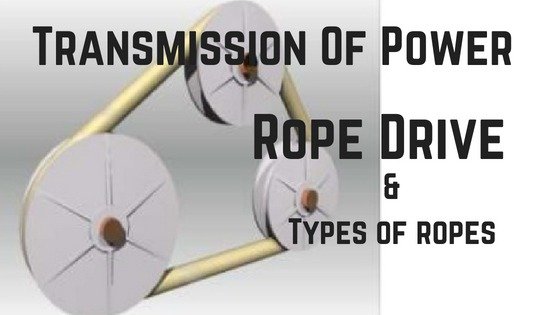
Rope drive is a form ofbelt drive, which is used for mechanical power transmission. Rope drives use multiple circular section ropes instead of single flats or V-belts. The rope drives are widely used where a large amount of power is to be transmitted, from one pulley to another, over a considerable distance.
The fibre ropes operate successfully when the pulleys are approximately 60 meters apart, while wire ropes are used when the pulleys are separated by 150 meters.
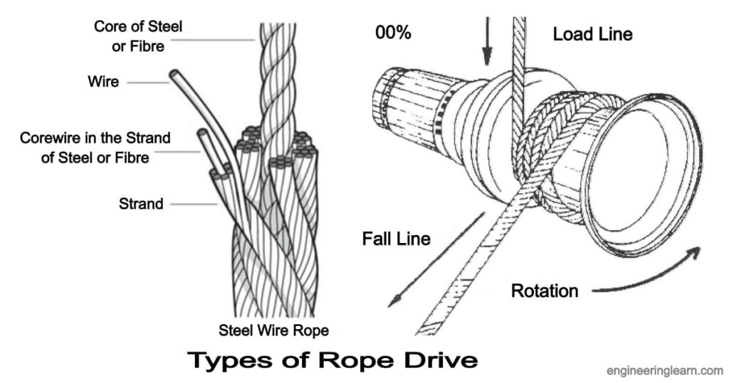
Wire rope is several strands of metal wire twisted into a helix forming a composite rope, in a pattern known as laid rope. Larger diameter wire rope consists of multiple strands of such laid rope in a pattern known as cable laid.
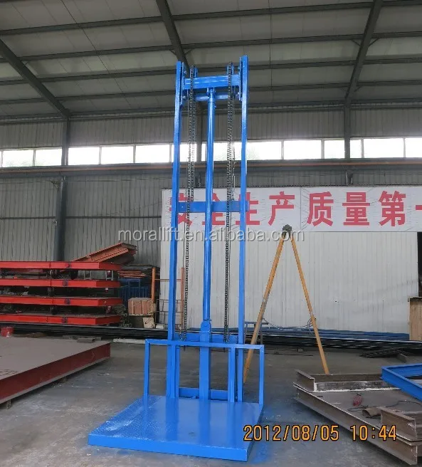
In the lifting and rigging industries, wire rope is attached to a crane or hoist and fitted with swivels, shackles or hooks to attach to a load and move it in a controlled matter. It can also be used to lift and lower elevators, or as a means of support for suspension bridges or towers.
Wire rope is a preferred lifting device for many reasons. Its unique design consists of multiple steel wires that form individual strands laid in a helical pattern around a core. This structure provides strength, flexibility, and the ability to handle bending stresses.
In stricter senses, the term wire rope refers to a diameter larger than 3/8 inch (9.52 mm), with smaller gauges designated cable or cords. Initially wrought iron wires were used, but today steel is the main material used for wire ropes.
Wire ropes are made from cold-drawn wires to increase strength and durability. It may be noted that as its size decreases the strength of the wire rope increases. The various materials used for wire ropes in order of increasing strength are iron, cast steel, extra-strong cast steel, steel, and alloy steel.
Wire ropes were developed starting with mining hoist applications in the 1830s. Wire ropes are used dynamically for lifting and hoisting in cranes and elevators, and for transmission of mechanical power.
It is also used to transmit force in mechanisms, such as a Bowden cable or the control surfaces of an airplane connected to levers and pedals in the cockpit.
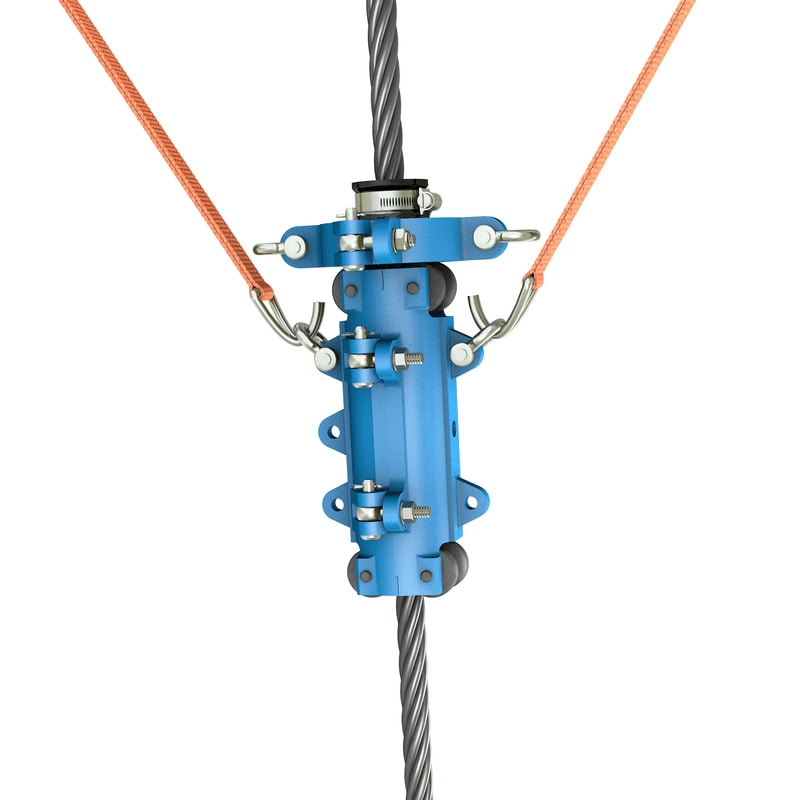
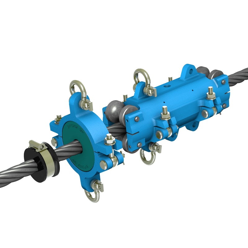
A wire rope clip, sometimes called a u-bolt clamp or u-bolt clip is used to clamp the loose end of a length of wire rope, once it has been looped back to form an eye. These fittings consist of a u-bolt and has a saddle secured by two nuts.
The advantages of a wire rope are that they are more resistant to wear, have better crushing resistance, and high strength compared to a round strand wire rope of equal diameter and classification. However, a swaged wire rope may have less bending fatigue resistance.
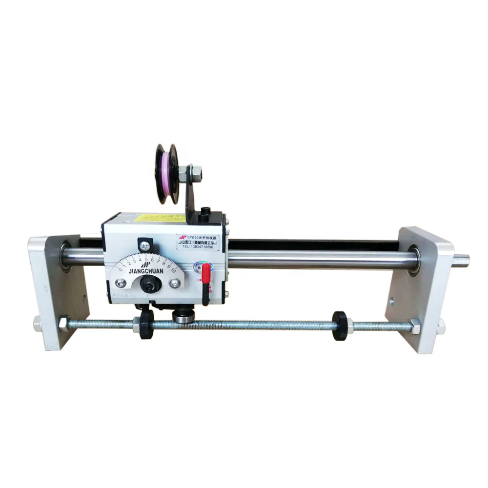
Wire ropes are made from various grades of the steel wire with tensile strength ranging from 1200 to 2400 MPa. The wires are first given special heat treatment and then cold drawn for high strength and durability of the rope. Steel wire ropes are manufactured by specialized machines.
First, strands such as 7, 19, or 37 of the wire are routed into a strand, and then a number of strands, usually 6 or 8, are rotated about the core or center to form the rope. The core may be made of hemp, jute, asbestos, or soft steel wire. The core must be continuously saturated with lubricant for the long life of the core as well as the entire rope.
Asbestos or soft wire cores are used when the ropes are subjected to radiant heat such as cranes working near furnaces. However, a wire core reduces the flexibility of the rope, and such ropes are used only where they are subjected to high compressions. Such as in the case of the wounding of multiple layers on a rope drum.
Cross or Regular Laying Ropes: In these types of ropes, the direction of twisting of wires in the strides is opposite to the direction of the twist of the stand. These types of ropes are the most popular.
Parallel or lang lay ropes: In these types of ropes, the direction of rotation of the strands in the strands is similar to the strands in the rope. These ropes have a better bearing surface but are easily split and twisted when loaded. These ropes are more flexible and the wearer is more effective. Since such ropes have a tendency to rotate, they are used in lifts and waved by guide methods and also as rope ropes.
The direction of the laying of ropes can be right-handed or left-handed, depending on whether the strands form a right-handed or left-handed helix. But right-handed ropes are most commonly used.
Fibre ropes are made from fibres of varying length depending on their source. these are twisted up into yarns, and the twist given binds the fibres firmly together so that they hold by friction when the yarn is subjected to strain. The yarns are then laid up to form rope.
Ropes for transmission power are usually made of fibrous materials such as cannabis, manila, and cotton. Since hemp and manila fibres are rough, the ropes made of these fibres are not very flexible and have poor mechanical properties. The hemp rope has less strength than the Manila ropes.
When the hemp and manila ropes are bent over the sheave. The fibres cause some sliding, causing the rope to rub internally. To reduce this defect, rope fibres are lubricated with a tar, elongated, or graphite. Lubrication also makes the rope moisture-proof. Hemp ropes are suitable only for hand-operated hoisting machinery and for tackling rope tack, hooks, etc.
The cotton cord is very soft and smooth. Lubrication of cotton ropes is not necessary. But if it is done, it reduces the external wear between the rope and its edge grooves. It may be noted that Manila ropes are more durable and stronger than cotton ropes. Cotton ropes are more expensive than Manila ropes.
Manila and cotton ropes typically have a diameter of 38 mm to 50 mm. The size of the rope is usually specified by its circumference or ‘circumference’.
The ultimate tensile braking load of fibre ropes varies greatly. For Manila ropes, the average value of ultimate tensile braking load can be taken as 500 D 2 kN and for cotton ropes, it can be taken as 350 D 2 kN, where D is the diameter of the rope in mm.
Power transmission over long distances is the main application of rope drive. Rope drives are used to drive systems that are more than 8 meters in distance using a distance power transmission system. Metal ropes are used for distances beyond sixty meters. It is commonly seen in elevators and cranes.
Rope drive is a form of belt drive, which is used for mechanical power transmission. Rope drives use multiple circular section ropes instead of single flats or V-belts. The rope drives are widely used where a large amount of power is to be transmitted, from one pulley to another, over a considerable distance.
Wire rope is several strands of metal wire twisted into a helix forming a composite rope, in a pattern known as laid rope. Larger diameter wire rope consists of multiple strands of such laid rope in a pattern known as cable laid.
A wire rope clip sometimes called a u-bolt clamp or u-bolt clip is used to clamp the loose end of a length of wire rope, once it has been looped back to form an eye. These fittings consist of a u-bolt and have a saddle secured by two nuts.
The term cable is often used interchangeably with wire rope. However, in general, wire rope refers to diameters larger than 3/8 inch. Sizes smaller than this are designated as cable or cords. Two or more wires concentrically laid around a center wire is called a strand.
Available in various constructions, sizes and finishes, wire rope is a versatile material that can be used to (among other things) lift, hoist, separate, position, secure, remove, repair, readjust, support and brace items in a safe and effective manner. Wire rope was initially designed to assist in the mining industry.
Dyneema is the world’s strongest fiber-producing ropes that are 15 times stronger than steel wire ropes of the same weight and has become one the most trusted fiber ropes over generic HMPE ropes and steel cable wire ropes for all rigging, maritime, mooring, and towing rope applications.
Overall, wire rope is stronger than chain. The multi-strands of continuous wires give wire rope its strength, whereas a chain is joined together with links. These joins are the weakest part of a chain and can break under heavy loads.
Wire rope is a preferred lifting device for many reasons. Its unique design consists of multiple steel wires that form individual strands laid in a helical pattern around a core. This structure provides strength, flexibility, and the ability to handle bending stresses.
The various materials used for wire ropes are iron, cast steel, extra strong cast steel, steel, and alloy steel, in order of increasing strength. For some purposes, wire rope can also be made from copper, bronze, aluminum alloys, and stainless steel.
In general, the higher wire count of a 7×19 typically makes it a better choice for winches, garage doors, and other applications that require tighter and more frequent turns, while the rigidity of a 7×7 makes it a good choice for automotive and aircraft controls.
Braided rope is stronger and is nicer on the hands than twisted rope, but it’s a pain to splice yourself. This means if you’re using a windlass and chain, and you are doing your own splicing, you’ll probably need to use twisted rope.
6 x 19S (Seale) -This is a good rope to withstand abrasion or crushing on the drum but its fatigue resistance is decreased. 6 x 25FW (Filler Wire) – To most wire rope users, 6 x 19 means 6 x 25 filler wire. It is a common rope in the 6 x 19 classification.
A wire rope is stronger because the material that makes it is continuous, i.e. without joins. In a chain, individual links must be closed by joining their ends, and that reduces the tension it can handle.
Compared to chain, steel wire ropes have a higher strength-to-weight ratio, making them easier to install and lighter on the floating structure. Steel wire ropes are most commonly constructed of many thin steel wires wound into strands, which are then wound around a central core into the final wire rope.
You should generally use equipment with a working load limit that is rated for weight at least five times higher – or 250,000 lbs. in this case. This recommendation is all thanks to the wire rope safety factor.
A rope that has more strands exhibits greater flexibility than one with fewer strands. Crush resistance: Although wire rope with a fiber core offers the most flexibility, it also demonstrates less resistance to crushing. If crushing is not a concern but flexibility is, fiber core wire rope is ideal.
The helix or spiral of the wires and strands in a rope is called the lay. Regular lay denotes rope in which the wires are twisted in one direction, and the strands in the opposite direction to form the rope. … These ropes are more likely to twist, kink and crush than regular lay ropes.
Flexible cable realize high flexibility and torque force transmission, ideal for drive cable for atherectomy, impeller, anchoring, and device release mechanism.
Gold wire features 99.99% purity and offers researchers a noble metal with biological inertness. Gold is softer than platinum and this feature may be used as an advantage in some applications.
... kPSI the more brittle the wire is but the better it retains its shape. The high kPSI wire is good for making straight electrodes that need to penetrate through tissue. The low kPSI is a softer more flexible ...
our magnesium alloy wire adopts the technical of super plasticity forming to improve the shortcomings of the low plasticity, which has the excellent plasticity much more than the normal magnesium alloys under the room ...
Back to the original analysis I made. The ratio of usable force difference to sum of tether tension forces is approx (0.45/2.45)~0.18 which is approx 1/5. So if the rope speed with slack return tether is approx 1/3 windspeed, with a 180 degree pulley at either side the rope speed must be minimum 5/3 times windspeed to transfer all the produced power.
Actually, one could probably chalk this up as +1 for rope drive vs yoyo as there will be less creeping on the drum (for yoyo the tether is reeled in at low tension and reeled out in high tension, leading to slippage and friction and thus wear on the tether). On the other hand, the tether on a rope drive will be passing the pulley 15 times more frequently compared to yoyo. I am unsure which of these is better
Motor 2 is arranged in the reel 1, and the outer end cap disjunctor of motor 2 has hollow shaft 3, has bearing 10 to be contained in an end of reel 1 on the hollow shaft 3, and the outer end that hollow shaft 3 stretches out bearing 10 is used for connecting fixing with support; The outer end 4 of motor shaft is adorned drg as required.The inner 5 of motor shaft connects with one heart and drives eccentric shaft 6, and off-centre is equipped with double-planetary gear 7 through bearing 13 in the middle of the eccentric shaft 6; Double-planetary gear 7 meshes with inner gear 8, inner gear 9 respectively.Inner gear 8 one ends are connected with bearing chamber, a client link of bearing chamber dress bearing 12 and eccentric shaft 6; The cylindrical of inner gear 8 and reel 1 be with the key close-fitting, direct drive reel 1.Inner gear 9 one ends have connecting shaft 17, in bearing 14 and eccentric shaft 6 one client links are housed; There is bearing 11 to connect outside the connecting shaft 17 of inner gear 9 with reel 1; Connecting shaft 17 stretches out the outer end of bearing 11 in order to the dress support.The disjunctor hollow shaft 3 of electric motor end cap and the connecting shaft of inner gear 9 17 support reel 1 with one heart.Motor reel 5 drives eccentric shaft 6 during work, drives double-planetary gear 7 operations.7 liang of gears of double-planetary gear mesh two inner geares 8 and 9 respectively, because ingear ratio of number of teeth difference in two groups makes inner gear 8 and inner gear 9 produce speed discrepancy, inner gear 9 is fixing, and inner gear 8 connections also drive reel 1 rotation.If motor 2 stalls and, reel 1 pull-up weight is stopped and not gliding motor shaft outer end 4 braking.

Our team understands that choosing the right cable assembly manufacturer, and pulleys for your cable assemblies requires thoughtful consideration, from bearing life, to minimum pulley diameter. Let Sava"s engineering expertise guide you toward the best selection of wire rope pulley wheels.
When cable is used over pulleys, the cable life can be significantly prolonged by proper pulley groove design. Laboratory tests on wire rope pulleys prove that improper groove design reduces cable bending life up to 90%. These same tests show that doubling a pulley diameter can increase cable bending life up to thirteen times what is otherwise typical. Also, pulley diameters less than sixteen rope diameters fall into a range in which cable life is relatively low.
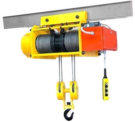
Whether you"re looking for a wire rope hoist with state-of-the-art or standard functionality, we offer wide solutions to meet our customers" needs. Our Demag wire rope hoists include excellent safety features, high handling rates, and cost-effective operation up to 100 tonnes.
As basic hoist units for integration into plant and machinery, or as lifting solutions with electronic controls that are optimized forcrane applications, with our wide range of wire rope hoists we offer the optimum solution to meet our customers’ specific requirements for efficiently lifting loads weighing up to 100 tonnes.
Our DMR modular wire rope hoists offer groundbreaking flexibility for diverse applications. With our DMR wire rope hoists, we can produce either a C-design or co-axial design. Some of the features include:

Rope Drive: Types, Application, Construction, Advantages & Disadvantages [Complete Guide] :- Rope drive is referred to as a simplified form of a belt drive, which is most commonly found having the application of power transmission mechanically. Rope drives are found performing multiple use of circular section ropes instead of the single flats or V-belts. The rope drives are the ones which are widely used where ever there seems to be a large amount of power that needs to be transmitted, from one pulley to another for any particular considerable distance.
The ropes which are used for the purpose of transmitting power are the ones which are usually made from the fibrous materials like hemp, manila and cotton.
The fibre ropes are referred to as those ropes which are usually found being operated successfully when the pulleys are found being approximately 60 meters apart from each other, whereas the wire ropes are found being used at the time when the pulleys are separated by 150 meters.
Wire rope is referred to as that rope which is found having several strands of metal wire twisted into a helix which forms a composite rope, in terms of the pattern which is commonly known to be the laid rope. Larger diameter of wire rope is found consisting of multiple strands of such laid ropes in a pattern which is commonly known as cable laid.
Commonly talking about the lifting as well as the rigging industries, wire rope is found being attached to a crane or hoist which is then fitted along with the swivels, shackles or hooks in order to attach to any load which moves it in a controlled matter. These types of ropes are very commonly used in order to lift or to lower the elevators in terms of the support for the suspension bridges or the towers.
Wire rope is commonly preferred for the purpose of lifting the devices for various types of requirements. The unique shapes of such type of rope is found consisting of multiple steel wires that is usually found forming individual strands which are easily laid in a helical pattern around a core. This structure is responsible for providing strength, flexibility, as well as the ability to handle bending stresses in such ropes.
In the technical world the wire rope is referred to as that which is found having a larger diameter as compared to any other with some smaller gauges that are known to be the designated cable or cords. Wrought iron wires are termed as those which were used in the ancient era, but today steel is known as the main material which is used for the wire ropes.
Wire ropes are usually referred to be made from various types of cold-drawn wires which is responsible for increasing the strength as well as the durability of the wire rope. The best thing to observe in wire rope is that, its size decreases, the strength of the wire rope increases which means that it has an inverse relation. There seem to be numerous materials which are found being used for the wire ropes to let it increase its strength using the materials like iron, cast steel, strong cast steel, steel, as well as alloy steel.
For some of these purposes, a wire rope is found being made up of copper, bronze, aluminium alloys, and stainless steel. The wire ropes are most commonly found being developed which starts with the mining hoist applications in the early 1830s. The wire ropes are found being used dynamically for the purpose of either lifting or hoisting in cranes and elevators, and for the transmission purposes of the mechanical power too.
The main aim of the wire rope is to transmit force in the mechanisms, like a Bowden cable or the control surfaces of an airplane which is found to be connected to the levers as well as pedals of the cockpit.
A wire rope clip is referred to as a u-bolt clamp or a u-bolt clip which is used in order to clamp the loose end of a length of wire rope as soon as it has been looped back in order to form an eye. These fittings consist of a u-bolt which has a saddle that are secured by two nuts.
Commonly, the wire rope assemblies are known to be the ones which are found having a need to at least two or three wire rope clips to let secure the ends properly along with the length of the rope.
Wire ropes are usually found being made from different grades of the steel wire having the tensile strength which can range from 1200 to 2400 MPa. The wires are initially found giving special heat treatment after which the cold is drawn for higher strength as well as durability of the rope. Steel wire ropes are found being manufactured by the specialized machines.
The core of the wire is found being made up of hemp, jute, asbestos, or soft steel wire. The core needs to be continuously saturated along with the lubricant for a better life of the core as well as the entire rope.
Asbestos or the soft wire cores are the ones which are usually used whenever the ropes are found being subjected to radiant heat like the cranes which are found working near the furnaces. Whereas, a wire core is found reducing the flexibility of the rope, and such ropes are the ones which are used only wherever they are subjected to high compressions, in case of wounding of multiple layers on a rope drum.
The advantages of a wire rope are that they are most commonly found to be more resistant to wear as they are found having better crushing resistance along with higher strength as compared to a round strand wire rope of equal diameter as well as classification. Whereas, a swaged wire rope is referred to as the one which might have less bending fatigue resistance.
According to the direction of twist of any particular individual wire and strands which are found being related to each other, the wire ropes can thus be classified as follows:
Cross or Regular Laying Ropes are referred to as those types of ropes wherein the direction of twisting of wires inside the strides is found being opposite as compared to the direction of the twist of the stand. These types of ropes are the ones which are found being most commonly used.
Parallel or lang lay ropes are referred to as those ropes which are found in the direction of rotation of the strands in the strands and is found similar to the strands in the rope. These ropes are found having a better bearing surface whereas these are easily split and are thus twisted when loaded. These ropes are known to be more flexible and effective as compared to any other type. Since these ropes are found having the tendency to rotate, they are most commonly used in the lifts and are waved by the guide methods and also as per the ropes.
Composite or reverse laid ropes are referred to as those types of ropes wherein the wires in two adjacent strands are found being rotated in the opposite directions.
The direction of the laying of ropes can either be right-handed or left-handed which depends upon the strands formed either right-handedly or left-handedly helix. But the right-handed ropes are most commonly used.
Fibre ropes are referred to as those ropes which are found being made from fibres of varying length that is also found being dependent on their source. These are the ones which are found being known to be made up of the twisted up rope from the yarns, wherein the twist is responsible for binding the fibres firmly together so that it can hold the friction whenever the yarn is subjected to undergo any kind of strain.
Ropes for transmission power are usually found being made up of fibrous materials like cannabis, manila, cotton etc. Since hemp and manila fibres are found to be rough, the ropes are found being made up of these fibres which are not very flexible and have poor mechanical properties too. The hemp rope is found having less strength as compared to the Manila ropes.
Once the hemp along with the manila ropes are observed to be bent over the sheave, the fibres might undergo some sliding that in result tends to cause the rope to rub internally. So, in order to reduce this defect, the rope fibres are found being lubricated with a tar, elongated, or graphite. Lubrication is also responsible for making the rope moisture-proof.
Rope drive is found having various applications which can be used for several purposes like hunting, pulling, carrying purposes, lifting purposes, as well as climbing activities in the ancient era.
Power transmission over long distances is found to be the main application of a rope drive. Rope drives are usually found being used in order to drive the systems that are usually found to be more than 8 meters in distance along with using a distance power transmission system. Metal ropes are the ones which are found being used for all the distances beyond 60 meters. These types of ropes are found to be seen commonly in the elevators as well as the cranes.

Guide ropes shall be tensioned with an applied load to maintain a minimum horizontal clearance of 25 mm (1 in.) from the cab enclosure to other structures in the tower at all times.A means shall be provided to indicate the minimum and maximum allowable tension in the guide ropes.
DESCRIPTION: During Connected Underway Replenishment (CONREP) operations, Navy Combat Logistics Force (CLF) ships connect to the receiving ship with a 1-inch wire rope highline at each solid cargo transfer station. The ship’s crew needs the ability to cut the highline quickly in the event of an emergency and prevent damage to equipment or injury to personnel.
The CLF ships currently employ a man-portable explosive emergency wire rope cutter at each solid cargo transfer station. The current emergency wire rope cutter uses explosive cartridges to drive the cutting blade through the wire rope. The Navy has not purchased any cartridges since 1989. While there are several thousand cartridges in inventory, no future acquisition of these explosive cartridges is planned. Additionally, there is no current program in place to assess and manage the fitness of the cartridges currently in inventory. The explosive nature of the cartridges requires special handling and storage procedures. A new tool will simplify the operations by eliminating the need to store and handle explosive cartridges during CONREP operations.
One vessel, the USNS ARCTIC (T-AOE 8), has a unique man-portable hydraulic wire rope cutter because of the 1 3/8 -inch wire rope highline installed on the prototype Heavy Underway Replenishment (UNREP) station. That specialized cutter is cumbersome and relies on a connection to a Navy Standard hydrostatic transmission to operate. This solution would not be usable on new CLF ships because the hydrostatic transmissions are not part of the newer UNREP technology.
The Navy needs an innovative tool to safely and reliably cut a 1-inch (or thicker) wire rope or cable within one second in an emergency. The Navy purchases the wire rope highline in accordance with RR-W-410, Paragraph 3.11.3.7, Type I, General Purpose, Class 3 Construction 6, 6 X 37, Uncoated, Independent Wire Rope Core (IWRC). The system should include appropriate redundant safety mechanisms to prevent premature cutting of the rope. In addition, the system should be scalable to wire ropes up to 1 3/8 -inch to account for any future Heavy UNREP requirements. The system should be man-portable, with minimum acquisition and integration costs of no more than $10,000 to $20,000 per UNREP Station. The cutter must be able to sever a 1-inch (minimum) wire rope or cable in under one second and be able to reliable sever 50 ropes without a failure. Additionally, the system should be able to operate at temperatures from -20°F to 125°F in marine environments.
PHASE I: Develop a conceptual design for a wire rope/cable cutting system. Demonstrate the conceptual basic cutting technology and perform an analysis of its ability to cut a representative wire rope or cable. Use both experimentation and physics-based modeling to determine the feasibility of the design concepts. Develop a Phase II plan. The Phase I Option, if exercised, will include the initial design specifications and capabilities description to build a full-scale prototype system in Phase II.
PHASE II: Develop and deliver a prototype system and validate it with respect to the topic’s objective. Construct and demonstrate a full-scale prototype wire rope/cable cutting system for testing and evaluation. Test the prototype in accordance with the Technical Warrant Holder’s direction to validate the cutting speed, reliability, and suitability of the system. Once the final prototype has completed the testing, the Technical Warrant Holder will be able to issue a Fit for Purpose letter for the system.
As packaged, the off-shore oil and gas industry may have similar emergency breakaway requirements for wire ropes. There may also be commercial crane and towing uses for the final product.
REFERENCES:1. Navy Tactics, Techniques and Procedures: Underway Replenishment (NTTP 4-01.4), March 2009. http://www.navybmr.com/study%20material/NTTP%204-01.4.pdf; 2. Federal Specification For WIRE ROPE AND STRAND (RR-W-410H). General Services Administration, Dec 2015. http://everyspec.com/FED_SPECS/R/RR-W-410H_54041/; 3. “How to Select and Operate a Hand Held Plasma Cutter.” Miller Electric Manufacturing, LLC. https://www.millerwelds.com/resources/article-library/how-to-select-and-operate-a-hand-held-plasma-cutter
KEYWORDS: Emergency Wire Rope Cutting; Emergency Steel Cable Cutting; Connected Underway Replenishment (CONREP) Operations; Emergency Breakaway; Tow Cable Disconnection; Heavy UNREP Requirements

These ropes can use at a distance up to 60m. Fiber ropes are commonly made of hemp, manila, or cotton. The ropes made from hemp and manila are not flexible and have inferior mechanical properties compared to the cotton. In order to occlude moving of fibers during bending and thus protect it from wear, manila and hemp belt are lubricated with tar or graphite. It also makes rope waterproof.
They used for power transmission over a large distance (they can transmit power over 150m). These are usually employed in an elevator and cranes. The wire ropes are made from twisting steel wires (other alloys used for special application).
The first multiple rope drive was a 9-rope drive of 200 bhp produced by Combe Barbourmanila hemp.vee pulley, as part of a Van Doorne or Variomatic transmission.textile machinery and differential speed gearing was often needed as part of the spinning process, where one shaft could be smoothly adjusted to run slightly faster or slower than another.
Rope drives were most widely used for power-transmission in mills and factories, where a single mill engine would have a large rope drive to each floor, where lineshafts across each floor distribute power to the individual machines. These multiple rope drives replaced the earlier technique of a vertical wrought iron shaft with bevel gears at each floor. They remained in use for as long as mills were driven by central steam engines, rather than individual electric motors.Droylesden split the output of one motor between two floors with two new rope drives.gas engines running on producer gas. A Yorkshire mill converted to use a 1,000 hp Allen diesel engine in 1938, and retained the rope drives.
Shaft drives had often used gearing from the engines to increase their speed, and thus their power transmission. This was avoided for rope drives, as the rope"s maximum useful speed could be achieved from the engine"s flywheel and flexibility of the ropes led to backlash in the gearing.
US practice sometimes used a single rope, looped between floors and tensioned by an idler pulley, but this system was not used in the UK and each loop was tensioned between its two pulleys by one of them being movable. Rope drives were also cheaper than belts - around a quarter of the price.
The rope drives were placed in a large diagonal shaft at the side of the building, usually windowless and distinctively visible from outside the building.
Rope drives required a larger such shaft than comparable belt or shaft drives. As the open shaft represented a channel for transmitting fires, unlike the narrow holes of a shaft drive, it needed careful fireproofing from the loom floors.
It was sometimes arranged for large drives that the engine drove a set of horizontal ropes to a pulley on a layshaft or "second motion shaft" alongside the engine house, then diagonally up through the shaft.
Vertical shafts were not widely used for rope drives in the UK, although were used for belts, as diagonal ropes could be made self-tensioning on the lower pulley under their own weight.


 8613371530291