
wire rope drum capacity calculator price
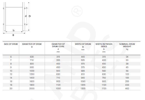
A handy tool for finding a cable drum that suits your needs - just enter your cable diameter and required length and it will return a list of matching cable drums.
All figures given are based upon a theoretical ‘tight pack’. It is recommended that an allowance of up to 30% be made to accommodate loose winding. A lower percentage could be used if the crew are known to always wind the drums neatly!
The combined weight of cable and drum is highlighted in orange when the weight exceeds 16kg. At this weight a user may need to make a risk assessment with respect to moving and/or carrying such without assistance.
† Drums with CTS suffix have an open hub "Cable Tail Support" on their flange. This would accommodate a further couple of metre"s of cable to allow the
‡Drums with CTF suffix have cable tail supports plus an additional flange, forming an 80mm wide extra section on the side of the drum to protect the tail. Calculated capacities are shown including and excluding the extra section.
First, a winch works harder the more wraps there are one the drum. This means that when your winch line is mostly spooled up it"s less powerful than when most of the line is played most of the way out. This is because of the increase in distance from the drum to the outer layer of the rope. Lay your arm on a table with 5 lbs in your hand and lift your hand while keeping your elbow on the table. Now tape the 5 lbs to a broomstick and tape the broomstick to your arm. It"ll be much harder with the object of movement much further away. Winch line length is a compromise between ability to reach anchors and power.
Second, more winch cable means that you can jam up your winch more easily. For example, if you do an extreme side pull for an extended period you"ll end up with a pile of cable on the side of the drum. This can damage your cable and damage your winch if you continue to reel in while your cable or rope is jammed.
If you really need more cable length you have three options:Get one of the high-strength, small-diameter winch lines. They are more expensive than regular synthetic but you get more line on the drum in a smaller diameter.
At the basis of any equipment selection, winches or otherwise, is an assessment of what is required in terms of capacity and capability. To enable the correct selection of winch, motor and gearbox, it is essential that basic application parameters as Load and Speed are known and understood. Below a brief explanation is given about the data and calculations required for the primary winch selection. The essence of winching is to move objects from one position to another by means of a length of rope. The rope is fixed to the object at one end, and to the winch drum on the other.
This makes power more understandable, since we know the required Nm (line pull x effective drum radius) to move the load and the required speed at which the load has to be moved. The higher the speed (at a given load), the more power we need.
With the required amount of power (kW) determined, the amount of torque (Nm) involved in the application must be determined. Depending on the effective drum radius and the load the torque at gearbox and motor level can be calculated. The amount of torque at gearbox level is important to make sure a sufficiently strong gearbox is chosen, and at motor level to make sure the load can be actually moved.
The effective drum radius used in this calculation is the distance between the centreline of the active rope layer and the centreline of the drum. For winches with only one layer of rope this is a constant factor. For winches with multiple layers the distance is a variable, and depends on the amount of rope wound on the drum. Please see Fig. 3-2 for the influence of the number of rope layers on the effective drum diameter.
Note:The rope diameter (required for the above calculation) follows from the nominal winch load, the required safety factor and the type of rope selected.
Selecting the correct gearbox, the maximum torque value during operation (or with an applied brake) is leading. In case of doubt go up one size of gearbox, the possibly too generous extra torque capacity of the gearbox will translate into a longer life. Make sure the calculated gearbox can be installed into or onto the winch and that it matches with the selected motor and resulting motor performance.
The winches found in the EMCÉ catalogue have drum diameters and lengths that have proven themselves during many years of real world use, and will be perfect for most standard applications. When special demands or requirements are present, it may be required to calculate with a non- standard drum. A few rules must be respected calculating a non-standard drum which are outlined below.
The minimum drum diameter follows from the minimum rope bending radius. Drum diameter/rope diameter ratio should not be too small since rapid rope wear will result, and for this reason the rope/drum ratio is stipulated in many regulations. The drum however may have a (much) larger diameter to enable storage of the required length of rope within a given drum width and number of rope layers. A larger diameter drum stores more rope for a given width, but also increases the effective drum radius and therewith the required torque for a given load. Make sure the diameter used in the calculation is an "existing" diameter i.e. a diameter that is available in the EMCÉ catalogue for (bigger) winches of the same model. Alternative dimensions can be specified, but will increase the cost of the modification unnecessary.
Note:Also make sure the drum flanges have a sufficiently large diameter to comply with the regulations. Depending on the regulation applicable the upper rope layer must remain 3-5 rope diameters below the edge of the flange. As with drum diameters it is advisable to use "existing" flange diameters. Again make sure an "existing" diameter is selected for the flanges, the same logic as for the drum diameter applies.
Drum width can be more or less chosen freely to suit the application, but increasing the drum width has a negative effect on the fleet angle of the winch rope, while at the same time winch footprint and winch cost increase. The EMCÉ standard drum dimensions as shown in the catalogue provide a sensible balance between rope storage, winch performance and winch dimensions.
Note:Make sure the drum width is sufficiently large to store at least an extra three safety wraps for steel wire rope and at least 6 safety wraps for man-made fibre ropes that will remain on the drum under all circumstances for safety reasons.
Frame dimensions usually result from the drum length and the combined length of transmission and motor. These dimensions can be derived from the catalogue information, and when a longer than standard drum is specified, the extra length can simply be added to the catalogue figures. Special care is required when bigger (longer) motors or gearboxes than standard are specified, or when extra equipment like clutches or band brakes are added to winches. Please contact the EMCÉ sales department for the effect this extra equipment will have on the frame dimensions. Make sure that the available space for installing the winch is sufficient for installing the winch itself and for the extra space required needed to operate and maintain the winch.
As an example, assume an output of 400 tons per 10 hours; shaft, with two compartments, 1000 ft. deep; hoisting in balance ; time available for hoisting, 6 h.; engine can hoist load in 1.5 min., and time to change cars 0.5 min. (the change at top and bottom of shaft being made at the same time). Then, 30 cars can be raised per hour, or 180 cars in 6 hours. This would require cars of 400 ÷ 180 = 2.22 tons capacity, to handle the desired output.
Having settled the size of the useful load to be hoisted, the size of the rope must be determined. This must be strong enough to hoist the total load, including its own weight, and to withstand the starting-stresses due to picking up the load suddenly when the rope is slack. Experiments have shown that, in starting with six inches of slack rope, the stress in the rope is about double that due to picking up the load gently.
This stress should not exceed 1/7 of the ultimate strength of the rope. The coefficient of friction, f, may be taken as .01 for vertical shafts, and as .02 to .04 for inclined shafts with rope well supported on rollers.
As an example, required to find size of rope necessary to hoist a total load of 5000 lbs. from a vertical shaft 1500 ft. deep. Assume, for a trial solution, that rope weighs 2 lbs. per ft. From equation 1, K=5000 lbs. X 2 +1500 X 2 lbs. + .01 X 8000 lbs. = 13,080 lbs., and ultimate strength of rope should be 7 X 13,080 =91,560 lbs., which would require a 1¼-inch- diameter flexible cast-steel rope, having an ultimate strength of 100,000 lbs., and weighing 2.45 lbs. per ft. This weight would increase R in above equation, and make 7 x K = 96,285, which is still less than the ultimate strength of the rope chosen. If a rope of lighter weight is desired, a plow-steel rope could be used instead of the cast-steel.
In the following discussion the loads will be considered as being hoisted from vertical shafts, as the principle remains the same for both classes, the only difference being that the stresses in the rope and on the engine and other parts of the machinery change with changes in the slope.
The minimum diameter of the drums is determined by the size of the rope used, and the larger the drums the smaller will be the bending-stresses and the more strength will be available for useful work.
Mr. William Hewitt has shown that, when the diameter of the sheave or drum is 44.5 times the diameter of a 19-wire cast-steel rope, the bending-stresses are 2/3 and the remaining useful strength is 1/3 of the “ maximum safe load ” that the rope will carry. The “ maximum safe load ” is taken as 1/3 the ultimate strength. This is well below the elastic limit of the wire. Thus the available strength is only 1/9 of the ultimate. In order to cut down the bending-stresses so as to leave of the ultimate strength of the rope available for useful work, the sheaves must be about 80 times the diameter of the rope. Other grades of rope require different diameter of drums, as will be seen by studying Tables I. and II.
k represents the bending-stress in pounds, E the modulus of elasticity = 28,500,000, a the aggregate area of the wires in square inches, R the radius of the bend in inches, d the diameter of the individual wires in inches, and C a constant depending on the number of wires in the strand. The values of d and C are, for 19-wire hoisting-rope : d = 1/15 diameter of rope, and C= 45.9.
As an example, required the working-load of a 1-in. cast-steel rope running over a 6-ft. sheave. From Table II. the bending-stress is found to be 9937 lbs., and from Table I. the “ maximum safe stress ” is found to be 22,667 lbs. The difference, 12,730 lbs., is the working-load.
The maximum length of a drum, aside from question of room, is controlled by the allowable fleet-angle, that is, the acute angle included between two lines drawn from the ends of the drum to the head sheave. This angle should not exceed 6°, in order that the rope may lead well on to the head sheave, and so that one rope will not grind or mount the next one in winding onto the drum. It is usual to place the drum far enough back from the head sheave to keep the fleet-angle within the limit; but where it cannot be done, it is necessary to guide the rope onto the head sheave and onto the drum by rollers or sheaves running on vertical spindles. The bisectrix of the fleet-angle should strike the middle of the drum.
Geared engines are made with small cylinders, and the engine proper runs at a speed of 100 to 200 r. p. m. The gearing usually gives a reduction of 1/3 to 1/5 so that the drum revolves at a moderate speed. The small cylinders make the first cost lower than that of a direct-acting engine; but the gearing for large hoists is a serious objection. The main gear has about the same diameter as the drum, so as to keep the pressure on the teeth as low as possible; and hence it has a circumferential speed equal to the speed of hoisting. Gearing, under very favorable conditions, should not run at a speed over 1200 ft. per min., and with the large cast gears and the rough work to which hoisting-engines are subjected, the speed should probably not exceed 900 ft. per min. If the average speed of hoisting is kept at about 2/3 of this maximum, the average speed will not exceed 600 ft. per min. This speed will allow the use of moderate-sized drums and keep the piston- speeds within the limits of good practice.
That gearing is liable to cause trouble and make considerable noise when run at a high speed, has been forcibly impressed on the mind of the writer by his experience in charge of a geared hoister, made by a reliable manufacturer, having cylinders each 18 in. dia. by 24 in. stroke, and two drums, each 7 ft. 6 in. dia. by 5 ft. face, on which three main gears, between 7 and 8 ft. dia., 3 in. pitch, and 9 in. face, were broken inside of nine months. The gears cost about $3000 each, besides the labor of replacing and the loss of 24 hours in changing the old for a new one. The engine was hoisting from a shaft 1000 ft. deep in about 1¼ min. The load of ore was 2½ tons.
Single-drum engines are limited to small outputs per day, or to places where the first cost of the plant is so important as to outweigh the loss in increased operating-expenses. This type of engine has many applications, as for sinking winzes, and for other inside work; also for shaft-sinking, and for working coal-mines on a small scale, where the cost of fuel is small, as waste material is burned. They are largely used in the Joplin, Mo., district, where the hoisting is from vertical shafts 100 ft. deep, the output often only 25 to 50 tons per day, and the ore is raised in buckets without guides, thus keeping the dead weight small, as compared with weight of ore raised. They are not adapted for regular mining work on a large scale, as the work expended in raising the cage, car and rope, each trip, would exceed the work of raising the ore.
Double-drum engines overcome the dead-work of hoisting the ore-carriers by balancing the weight of the cage and car in one compartment against those in the other. They are thus more economical to operate than a single-drum engine, and the cost of installing will probably not be over 50 per cent, greater than for a single-drum engine. The cost of sinking a shaft large enough for two hoisting-compartments and a manway is not much more than that of a shaft with only one hoisting-compartment and a manway; the head buildings must be nearly the same in either case; and the double-drum engine will have smaller cylinders, thus partly offsetting the cost of the second drum.
With cylindrical drums, the ropes in the two compartments, from the cages to the head sheaves, are of constantly varying lengths, and are in balance only when the cages are passing at the center. With double conical drums, the work on the engine is kept constant by giving the cage at the bottom the short leverage of the small end of the drum, and the cage at the top the longer leverage of the large end of the drum.
The Koepe system, as applied to a double-compartment shaft, has a tail-rope passing from the bottom of one cage down and around an idle sheave at the bottom of the shaft, and up to the other cage. Thus the weight of the rope in the two compartments is exactly equal, and the whole hoisting mechanism is in balance at all points of the trip.
The flat-rope system of hoisting attempts to equalize the work on the engine by coiling a rope of rectangular cross-section on a reel, like a surveyor’s linen tape; so that the diameter of the reel increases and the leverage of the load increases as the weight of the constantly shortening rope decreases. Thus the work on the engine is kept constant, when the rate of increase of leverage and decrease of weight are in inverse proportion to each other. The flat ropes, however, are heavier than round ropes of the same strength, are shorter-lived, and cost more at first and for subsequent care. The flat-rope system is very largely used in Montana, and in some other districts which have followed the Montana practice.
The peculiarities of the different types of engines are brought out more fully by the calculation of the size of their cylinders when equipped with the different arrangements of drums.
At the instant of starting, the power in one cylinder acting on the crank, in the top or bottom position, must have a moment equal to or greater than the moment of the unbalanced load pulling from the circumference of the drum. After starting, the other cylinder comes in to accelerate the speed, and the two together are able to hoist the load with steam partially cut off and still maintain the full speed.
Then, for a single-drum, direct-acting engine, Fig. 1, the moment of the load = (W + F) D/2 and the moment of the engine = (P x A x e)L/2. Placing these equal to each other,
If the drum is geared, the engine will make g revolutions to one of the drum, or the leverage of the engine is increased to g times what it would be if directly connected, and the equation becomes
When the weight of the load, size of the drum, and steam pressure are given to determine the size of the cylinders, there are two unknown quantities in the equation, viz.: A and L. Here L can be assumed and the equation solved for A, from which the diameter can be obtained. The usual practice is so to proportion the cylinder that the length of travel is 1¼ to 2½ times the diameter of the piston. If the value of L chosen for trial gives a ratio of stroke to diameter outside of these limits, another value must be taken for L, and another solution made. If the ratio is decided upon first, then the area can be expressed in terms of the stroke, and there is only one unknown quantity in the equation. Thus rd =12L or d = 12L/r (12L being the length of the stroke in inches), and A = π d²/h = π x 144L²/4r²; which substituted in equation 5 , gives
Having obtained the size of cylinders, and knowing the speed of hoisting and size of drum, the speed of the engine can be obtained, and the speed of the piston can be investigated. The speed of hoisting, in feet per min., divided by the circumference in feet, will give the number of revolutions of the drum per minute. If the drum is geared, the engine will make g times as many r. p. m. (revolutions per minute) as the drum, and
As an example, take a double-cylinder engine geared to a single drum, to find the size of cylinders required under the following known conditions : Vertical shaft is 400 ft. deep, cage to be hoisted in one minute; the-weights are, cage 900 lbs., car 600 lbs., ore 1500 lbs., rope 400 lbs.; steam pressure, P, is 60 lbs., e = 0.7, g = 4/1, f = .01 (assumed), D = 4 ft. and L may be taken as 1½ ft. for a trial solution; then,
With double-drum hoisters, where the descending cage and car counterbalance the ascending ones, the general equation 5 still applies, but the value of W and F are changed. Referring to Fig. 2, when a loaded car is to be started from the bottom of the shaft and an empty car is being lowered at the same time,
Or, instead of shortening the stroke, the number of revolutions can be cut down by increasing the diameter of the drum; thus, if D = 9 ft. and L = 4 ft., d will be 27¾ in., the ratio 12L/d = 1.73, and the piston-speed = 566 ft. per min.
Conical drums, as already noted, are intended to equalize the varying load on the engine, due to the change in length and weight of the rope as the cage ascends and descends. As these engines are used where every economy is desirable, they are usually direct-acting and fitted with double drums.
(C + O + Rl) D/2 – (C + Rs) y/2 = moment of the resistance when the load is at the bottom, Fig. 3, position A, and (C+O+Rs)y/2-(C+Rl)D/2 = moment of the resistance when the load is at the top, Fig. 3, position B. The object of the conical drums being to keep this moment constant, these two values must be equal, and
Taking as an example the one used for the engine with double cylindrical drums, depth of shaft 2000 ft. plus 33 1/3 ft. to head sheave above landing, S = 2000 ft. per min., O = 5000 lbs., C = 5000 lbs., Rl = 6100 lbs., Rs. = 100 lbs., D = 7 ft., P = 60 lbs., g = 1, f = .01, e = 0.7, L for trial = 4 ft., to find diameter of cylinder.
There must be a division left between the ropes on a conical drum in order to furnish positive grooves for the rope, so that the large coils cannot slip down over the smaller ones; hence the drum must be longer than those of the cylindrical design, even when the mean diameter of the conical drum is the same as the diameter of a cylindrical one.
In the Koepe system, as applied to a double-compartment shaft, there is a tail-rope of the same weight as the hoisting-rope fastened to the bottom of one of the cages, passed around a sheave in a pit at the bottom of the shaft, and attached to the bottom of the other cage. Then, in whatever position the cages are in the shaft, there is the same weight of rope hanging in each compartment. Thus the entire weight of the hoisting mechanism is in perfect balance at all times, and the engine only has to raise the weight of the ore and overcome the friction of the moving parts. The main rope may be wound on a pair of cylindrical drums, or it can be wrapped back and forth over a pair of multiple-grooved sheaves, as is done in rope drives for many purposes. It is essential that a positive grip is taken on the rope by the driving mechanism, or else its creeping on the driving-sheaves will make the indicators show a false position for the cages, and make accidents of overwinding a great, source of danger.
The conditions in all of the above were the same as used in former examples, except that the diameters of drums are all taken as 9.76 ft., which is the mean diameter of the conical drums. The engines are direct-acting, the shaft has double compartments, and the cages work in balance; C =5000 lbs., O = 5000 lbs., R = 6100 lbs., P = 60 lbs., L = 4 ft., f = .01, e = 0.7, g = 1, S = 2000 ft. The piston-speed is 522 ft. per min. in each case.
The table shows that cylindrical drums are not as economical to operate as either the conical drums or the Koepe system. The conical drums are expensive to make, as the grooves have to be formed spirally and with an increasing radius, and each problem requires a specially-designed drum, so there can be little use made of stock patterns. They are only used where the rope is heavy, and the economy of accurate counter-balancing is clearly indicated, and will offset the extra cost of manufacture.
The Koepe system is a simple method of counter-balancing, and the principle could often be applied to existing plants with cylindrical drums by adding a tail-rope and an idle sheave at the bottom of the shaft, provided there is sufficient sump-room for the sheave and its slide. The objection to the Koepe system, where used without drums, is the liability of the ropes to creep on the sheaves, causing the indicators to give a false record and so increase the danger of overwinding.
Flat ropes of rectangular cross-section are wound on a reel like a tape. When the load starts from the bottom of the shaft the rope winds on the center of the reel, which is of small diameter, and then, as the load rises, the successive layers increase the diameter of the coil on the reel; thus the leverage of the load increases and the weight decreases. If the original diameter of the barrel of the reel and the thickness of the rope are properly chosen, the moment of the resistance will be constant.
From equation 13, knowing t, the value of y can be obtained, or having decided on y, the equation can be solved for t. The minimum diameter of the barrel, D, depends on the thickness of the rope, and can be calculated from Mr. Hewitt’s equation, previously given : k = Ea/2.06 R/d + C in which k= bending-stress in pounds, E = modulus of elasticity = 28,500,000, a = aggregate area of the wire in sq. in., R = radius of the bend in inches, d = diameter of individual wires, and C a constant depending on the number of wires in a strand. With flat rope, d = 1/6 the thickness of the rope, and C = 27.54.
The ideal case would be one in which the work of hoisting was constant at every part of the hoist; but the thickness of the rope may be such that the leverage of the load increases faster or slower than the weight of the load decreases, thus making the work on the engine to vary daring the trip. In such a case, the design must be tested with the cage at various points, to make sure that the engine has sufficient power to handle the loads at the desired speed at all points. For this, equations 9 and 10 may be used.
Generally these hoists are arranged in pairs, so that one cage ascends while the other descends. Then the necessary large diameter of the reel, to make the work constant on the engine, can be found by equation 11, used for conical drums, and the size of the engine from equation 12. After this the thickness of the rope can be found by equation 13.
If the reels cannot be made of such diameter as to make the work of hoisting uniform throughout the trip, with a reasonable thickness of rope, then the case must be considered by itself, and the design must be tested with the cage in positions sufficiently numerous to prove that the engine that will start the load is strong enough to handle it at all points.
Wire rope and cable are each considered a “machine”. The configuration and method of manufacture combined with the proper selection of material when designed for a specific purpose enables a wire rope or cable to transmit forces, motion and energy in some predetermined manner and to some desired end.
Two or more wires concentrically laid around a center wire is called a strand. It may consist of one or more layers. Typically, the number of wires in a strand is 7, 19 or 37. A group of strands laid around a core would be called a cable or wire rope. In terms of product designation, 7 strands with 19 wires in each strand would be a 7×19 cable: 7 strands with 7 wires in each strand would be a 7×7 cable.
Materials Different applications for wire rope present varying demands for strength, abrasion and corrosion resistance. In order to meet these requirements, wire rope is produced in a number of different materials.
Stainless Steel This is used where corrosion is a prime factor and the cost increase warrants its use. The 18% chromium, 8% nickel alloy known as type 302 is the most common grade accepted due to both corrosion resistance and high strength. Other types frequently used in wire rope are 304, 305, 316 and 321, each having its specific advantage over the other. Type 305 is used where non-magnetic properties are required, however, there is a slight loss of strength.
Galvanized Carbon Steel This is used where strength is a prime factor and corrosion resistance is not great enough to require the use of stainless steel. The lower cost is usually a consideration in the selection of galvanized carbon steel. Wires used in these wire ropes are individually coated with a layer of zinc which offers a good measure of protection from corrosive elements.
Cable Construction The greater the number of wires in a strand or cable of a given diameter, the more flexibility it has. A 1×7 or a 1×19 strand, having 7 and 19 wires respectively, is used principally as a fixed member, as a straight linkage, or where flexing is minimal.
Selecting Wire Rope When selecting a wire rope to give the best service, there are four requirements which should be given consideration. A proper choice is made by correctly estimating the relative importance of these requirements and selecting a rope which has the qualities best suited to withstand the effects of continued use. The rope should possess:Strength sufficient to take care of the maximum load that may be applied, with a proper safety factor.
Strength Wire rope in service is subjected to several kinds of stresses. The stresses most frequently encountered are direct tension, stress due to acceleration, stress due to sudden or shock loads, stress due to bending, and stress resulting from several forces acting at one time. For the most part, these stresses can be converted into terms of simple tension, and a rope of approximately the correct strength can be chosen. As the strength of a wire rope is determined by its, size, grade and construction, these three factors should be considered.
Safety Factors The safety factor is the ratio of the strength of the rope to the working load. A wire rope with a strength of 10,000 pounds and a total working load of 2,000 pounds would be operating with a safety factor of five.
It is not possible to set safety factors for the various types of wire rope using equipment, as this factor can vary with conditions on individual units of equipment.
The proper safety factor depends not only on the loads applied, but also on the speed of operation, shock load applied, the type of fittings used for securing the rope ends, the acceleration and deceleration, the length of rope, the number, size and location of sheaves and drums, the factors causing abrasion and corrosion and the facilities for inspection.
Fatigue Fatigue failure of the wires in a wire rope is the result of the propagation of small cracks under repeated applications of bending loads. It occurs when ropes operate over comparatively small sheaves or drums. The repeated bending of the individual wires, as the rope bends when passing over the sheaves or drums, and the straightening of the individual wires, as the rope leaves the sheaves or drums, causing fatigue. The effect of fatigue on wires is illustrated by bending a wire repeatedly back and forth until it breaks.
The best means of preventing early fatigue of wire ropes is to use sheaves and drums of adequate size. To increase the resistance to fatigue, a rope of more flexible construction should be used, as increased flexibility is secured through the use of smaller wires.
Abrasive Wear The ability of a wire rope to withstand abrasion is determined by the size, the carbon and manganese content, the heat treatment of the outer wires and the construction of the rope. The larger outer wires of the less flexible constructions are better able to withstand abrasion than the finer outer wires of the more flexible ropes. The higher carbon and manganese content and the heat treatment used in producing wire for the stronger ropes, make the higher grade ropes better able to withstand abrasive wear than the lower grade ropes.
Effects of Bending All wire ropes, except stationary ropes used as guys or supports, are subjected to bending around sheaves or drums. The service obtained from wire ropes is, to a large extent, dependent upon the proper choice and location of the sheaves and drums about which it operates.
A wire rope may be considered a machine in which the individual elements (wires and strands) slide upon each other when the rope is bent. Therefore, as a prerequisite to the satisfactory operation of wire rope over sheaves and drums, the rope must be properly lubricated.
Loss of strength due to bending is caused by the inability of the individual strands and wires to adjust themselves to their changed position when the rope is bent. Tests made by the National Institute of Standards and Technology show that the rope strength decreases in a marked degree as the sheave diameter grows smaller with respect to the diameter of the rope. The loss of strength due to bending wire ropes over the sheaves found in common use will not exceed 6% and will usually be about 4%.
The bending of a wire rope is accompanied by readjustment in the positions of the strands and wires and results in actual bending of the wires. Repetitive flexing of the wires develops bending loads which, even though well within the elastic limit of the wires, set up points of stress concentration.
The fatigue effect of bending appears in the form of small cracks in the wires at these over-stressed foci. These cracks propagate under repeated stress cycles, until the remaining sound metal is inadequate to withstand the bending load. This results in broken wires showing no apparent contraction of cross section.
Experience has established the fact that from the service view-point, a very definite relationship exists between the size of the individual outer wires of a wire rope and the size of the sheave or drum about which it operates. Sheaves and drums smaller than 200 times the diameter of the outer wires will cause permanent set in a heavily loaded rope. Good practice requires the use of sheaves and drums with diameters 800 times the diameter of the outer wires in the rope for heavily loaded fast-moving ropes.
It is impossible to give a definite minimum size of sheave or drum about which a wire rope will operate with satisfactory results, because of the other factors affecting the useful life of the rope. If the loads are light or the speed slow, smaller sheaves and drums can be used without causing early fatigue of the wires than if the loads are heavy or the speed is fast. Reverse bends, where a rope is bent in one direction and then in the opposite direction, cause excessive fatigue and should be avoided whenever possible. When a reverse bend is necessary larger sheaves are required than would be the case if the rope were bent in one direction only.
Stretch of Wire Rope The stretch of a wire rope under load is the result of two components: the structural stretch and the elastic stretch. Structural stretch of wire rope is caused by the lengthening of the rope lay, compression of the core and adjustment of the wires and strands to the load placed upon the wire rope. The elastic stretch is caused by elongation of the wires.
The structural stretch varies with the size of core, the lengths of lays and the construction of the rope. This stretch also varies with the loads imposed and the amount of bending to which the rope is subjected. For estimating this stretch the value of one-half percent, or .005 times the length of the rope under load, gives an approximate figure. If loads are light, one-quarter percent or .0025 times the rope length may be used. With heavy loads, this stretch may approach one percent, or .01 times the rope length.
The elastic stretch of a wire rope is directly proportional to the load and the length of rope under load, and inversely proportional to the metallic area and modulus of elasticity. This applies only to loads that do not exceed the elastic limit of a wire rope. The elastic limit of stainless steel wire rope is approximately 60% of its breaking strength and for galvanized ropes it is approximately 50%.
Preformed Wire Ropes Preformed ropes differ from the standard, or non-preformed ropes, in that the individual wires in the strands and the strands in the rope are preformed, or pre-shaped to their proper shape before they are assembled in the finished rope.
This, in turn, results in preformed wire ropes having the following characteristics:They can be cut without the seizings necessary to retain the rope structure of non-preformed ropes.
They are substantially free from liveliness and twisting tendencies. This makes installation and handling easier, and lessens the likelihood of damage to the rope from kinking or fouling. Preforming permits the more general use of Lang lay and wire core constructions.
Removal of internal stresses increase resistance to fatigue from bending. This results in increased service where ability to withstand bending is the important requirement. It also permits the use of ropes with larger outer wires, when increased wear resistance is desired.
Outer wires will wear thinner before breaking, and broken wire ends will not protrude from the rope to injure worker’s hands, to nick and distort adjacent wires, or to wear sheaves and drums. Because of the fact that broken wire ends do not porcupine, they are not as noticeable as they are in non-preformed ropes. This necessitates the use of greater care when inspecting worn preformed ropes, to determine their true condition.
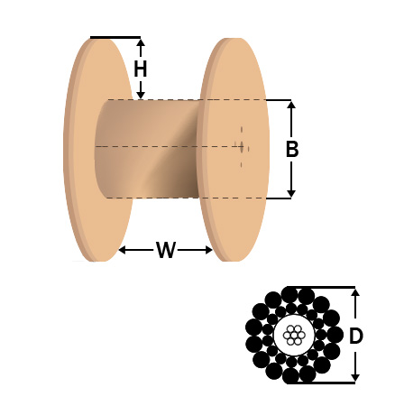
When placing an order, it"s important to know how many reels you can expect. To know how much wire or cable will fit on a shipping reel, enter the diameter of your cable in inches below. Our Reel Capacity Calculator will show how many feet or meters of that cable will fit on our different reels.
All slings of a web type fabric, nylon or other synthetic material should be labeled to indicate their load rating capacity. They should not be used in a manner that would allow the sling to be cut. Nylon slings available for construction are:
The same sling will have a different capacity for each hitch. The choker has the lowest capacity. The vertical hitch has an additional 25% capacity and the basket hitch is twice the vertical hitch capacity. The horizontal degree of a two-point pick will affect the load capacity of your sling
Avoid shock loading to nylon or wire rope slings when beginning your lift. The crane or hoist should be engaged slowly until the load is suspended. The speed in which you lift or lower the load should be increased or decreased gradually. Sudden starts or stops place a heavy load on the slings and load line, up to 50 times the actual weight. Once any sling has been shock loaded it must be removed from service.
Manufacturers identify their classes of wire ropes beginning with two numbers such as 6x25. The "6" means that there are 6 strands or larger wires making up the wire rope and the second number "25" means that there are 25 smaller wires laid around each other to make up each strand. The other wires in some wire ropes are called filler wire. Wire fatigue resistance will increase as the number of wires per strand increases.
Known as the industry workhorse of wire ropes, the 6x25 Filler Wire maintains a good balance between resistance to abrasion and fatigue resistance. When both abrasion resistance and fatigue resistance are required, the 6x26 Warrington Seale is a better alternative.
Keep the wire rope lubricated so that rust and dirt will not weaken it by acting as an abrasive on the rope as it spools through the sheaves and drums. Lubrication of the rope allows individual wires to move and work together so that all the wires carry the load instead of just a few. Weather and other exposures can also remove
Natural and synthetic fiber rope offerings have expanded over the past years with the introduction of new materials such as Kevlar and other advancements that can provide a higher strength and a better
Recommended working loads will vary according to the rope size, type and manufacturer. Twisted rope is oftentimes has the working load listed between 10% to 15% of the tensile strength and braided rope is between 15% to 20%. Therefore, a braided rope with a listed tensile strength of 12,500 pounds might only have a safe working load of 1,850 pounds. Ropes have different qualities and you should carefully assess your rigging requirements. In example, Kevlar has a considerably higher breaking strength than most available products,
It is necessary to check with your cordage vendor to obtain the safe working load of your rope prior to purchasing it for any rigging or lifting purpose!
Many factors, including rope usage, load conditions and weather exposure affect the rope’s working load capabilities. You should inspect your rope daily for concentrated wear. It must be free of frayed strands and broken yarns, cuts and abrasions, burns and discoloration. If there is excessive soiling or paint buildup, place it out of service. Check for chemical or heat damage and ultraviolet deterioration. This type of degradation is indicated by discoloration and the presence of splinters and slivers on the rope surface. Do not use wire rope or V-belt sheaves for synthetic rope as the rope will be pinched inside.
6x36 is a flexible general engineering wire rope readily available in galvanised, ungalvanised and marine grade stainless steel. The wire rope has an equal lay construction (warrington seale) and achieves a superior breaking load to the 6x19 construction range. The construction has been designed to give a flexible rope with a good fatigue life. A 6x36 wire rope is available with either FC (fibre core) or IWRC (independent wire rope core) and is used for a wide range of applications, examples of which are shown below:


 8613371530291