
wire rope drum groove design brands

Drums are the means by which power is transmitted to the rope and thence to the object to be moved. For the wire rope to pick up this power efficiently and to transmit it properly to the working end, installation must be carefully controlled.
The end of the rope must be secured to the drum by such means as will give the end termination at least as much strength as is specified by the equipment manufacturer.
It is preferable to have at least three dead wraps remaining on the drum when the rope is unwound during normal operation. Three dead wraps are a mandatory requirement in many codes and standards.
If the wire rope is carelessly wound and, as a result, jumps the grooves, it will be crushed and cut where it crosses from one groove to the other. Another, almost unavoidable problem is created at the drum flange; as the rope climbs to a second layer there is further crushing and the wires receive excessive abrasion. Riser and filler strips may help remedy this condition.
Another factor that must be given serious consideration is the pitch of the drum grooves relative to the actual rope diameter. Wire rope is normally manufactured to a plus tolerance. (See Table 3.) If this oversize tolerance in the rope is not taken into account, it can mean severe damage.
As an example, a grooved drum made for 1/4-inch rope may have a pitch of .250 inches. Yet, by Federal standards, a 1/4-inch rope may have a diameter as large as .265 inches. If a rope of this size were to be operated on a drum with a .250 inch pitch, crowding would occur and the rope would be forced out of the groove.
Installation of a wire rope on a plain (smooth) face drum requires a great deal of care. The starting position should be at the correct drum flange so that each wrap of the rope will wind tightly against the preceding wrap (Fig. 32). Here too, close supervision should be maintained during installation. This will help make certain that:
Loose and uneven winding on a plain (smooth) faced drum can, and usually does, create excessive wear, crushing and distortion of the rope. The results of such abuse are lower operating performance and a reduction in the rope’s effective strength. Also, for an operation that is sensitive in terms of moving and spotting a load, the operator will encounter control difficulties as the rope will pile up, pull into the pile and fall from the pile to the drum surface. The ensuing shock can break or otherwise damage the rope.
Under normal conditions, sheaves and drums receive periodic inspections, and their overall condition is recorded. Such inspections usually include the drum, sheaves, and any other parts that may come into contact with the wire rope and subject it to wear. As an additional precaution, rope related working parts, particularly in the areas described below, should be reinspected prior to the installation of a new wire rope.
The very first item to be checked when examining sheaves and drums, is the condition of the grooves (Figs. 35, 36 and 37). To check the size, contour and amount of wear, a groove gage is used. As shown in Figure 35, the gage should contact the groove for about 150º of arc.
Two types of groove gages are in general use and it is important to note which of these is being used. The two differ by their respective percentage over nominal rope diameter.
For new or remachined grooves, the groove gage is nominal plus the full oversize percentage. The gage carried by most wire rope representatives today is used for worn grooves and is made nominal plus _ the oversize percentage.
This latter gage is intended to act as a sort of “no-go” gage. Any sheave with a groove smaller than this must be regrooved or, in all likelihood, the existing rope will be damaged.
When the sheave is regrooved it should be machined to the dimensions for “recommended minimum new groove” given in Table 12. This table lists the requirements for new or remachined grooves, giving the groove gage diameter in terms of the nominal wire rope diameter plus a percentage thereof. Similarly, the size of the “no-go” gage is given, against which worn grooves are judged. Experience has clearly demonstrated that the service life of the wire rope will be materially increased by strict adherence to these standards.

Multi-layer drum systems should use strand- or swage compacted Python® rope constructions having a steel core. The higher fill factor of such rope constructions will offer a greater resistance to crushing and flattening than conventional rope types. This is particularly important for boom hoist ropes on lattice boom cranes at the cross over point from one rope winding to the next.
Cranes equipped with multi-layer drum systems which require rotation-resistant or non-rotating rope are best served with Python Compac® 18 and Python Compac® 35. To further reduce drum crushing have the rope layers wound onto the drum with about 5-10% of the WLL and avoid that the first layer unspools and re-spools without tension. This would cause a ‘soft’ bottom layer which will flatten rather quickly.

Generally, we recommend grooved drums only. The rope is spooled properly and positively. Depending on the drum/rope diameter relationship helix-grooved drums can be used for up to 3 layers without excessive rope wear. For applications with more than 3 layers (e.g. Mobile cranes) we recommend ‘Lebus’ grooving.
It has to be remembered, however, that rope service life on multiple layer drum systems will always only be a fraction of that compared with single layer helix-grooved drums.
If these values are applied to single layer grooved drums the maximum permissible rope-deflection angle for regular wire rope constructions is 4°. For non rotating /rotation-resistant ropes the maximum permissible deflection angle is 1.5° only.

The primary purpose of the LeBus Spooling System is to spool wire rope or cable onto hoisting drums in a true and correct manner. In most spooling operations, you never encounter severe spooling problems when spooling only one layer of cable on your drum. In all other cases, your trouble will begin when you start the second layer and from there on up through your last layer.
The LeBus System is the only system on the market that can eliminate the 360o continuous cross winding of the cable as found on smooth drums. The LeBus System cuts down the cross winding to approximately 20% of the circumference of the drum while 80% of the wraps are parallel with the flanges. In view of this pattern, each layer of wire rope then becomes the groove pattern for each succeeding layer.
The LeBus pattern puts the same number of coils on each layer thereby eliminating the "cutting-in" of the cable. This severe scrubbing action can cause the wire rope to fail prematurely. The LeBus System is the only known method that can accomplish this feat. Therefore it creates a much safer environment. Another benefit is increased wire rope life. Since the wire is not "cutting in" and scrubbing on itself, the true pyramid stacking pattern promotes long rope life.
Flexibility is an asset that cannot be overlooked. The sleeve can be added to the smooth drum either during original manufacturing or after the hoist is in the field.
The name LeBus has been around the oil field industry since it was just a blacksmith shop in 1900. LeBus started out by manufacturing speciality tools for the booming west Texas oil fields. Tool pushers and/or owners would see a specific need for a new tool and LeBus would forge the new tools on demand. Soon LeBus was into the manufacturing and selling of fishing tools, drill collars, tool joints and rotary bits. LeBus manufactured the "Eureka Pipe Wrench" and the "Slip Socket Overshot". The common element in each case was the hoisting machinery, specifically the drum and wire rope, which was the main "workhorse" of the drilling rig. LeBus noticed that the wire rope would not lay in a consistent pattern on the drum. This caused undue wear and scrubbing of the wire rope. Something better was on the horizon.

Sheaves, drums and rollers must be of a correct design if optimum service is to be obtained from both the equipment and the wire rope. Because there are many different types of equipment and many different operating conditions, it is difficult to identify the one specific size of sheave or drum most appropriate for every application.
The guideline to follow is this: the most practical design is the one that most closely accommodates the limiting factors imposed by the equipment, the operating conditions and the wire rope.
All wire ropes operating over sheaves and drums are subjected to cyclic bending stresses, thus the rope wires will eventually fatigue. The magnitude of these stresses depends—all other factors being constant—upon the ratio of the diameter of the sheave or drum to the diameter of the rope.
Frequently, fatigue from cyclic, high-magnitude bending stress is a principal reason for shortened rope service. In order for a rope to bend around a sheave, the rope’s strands and wires must move relative to one another. This movement compensates for the difference in diameter between the underside and the top side of the rope, the distance being greater along the top side than it is on the underside next to the groove.
Proper rope movement (and service) is adversely affected if the wires cannot adjust to compensate for this length differential. Also, there can be additional limitations to wire movement because of excessive pressure caused by a sheave groove diameter which is too small, or by lack of rope lubrication. Avoid changing the bending direction from one sheave to another as this reverse bending further accelerates wire fatigue.
The relationship between sheave diameter and rope diameter is a critical factor that is used to estimate the rope’s fatigue resistance or relative service life. It is expressed in the D/d ratio mentioned earlier in which D is the pitch diameter of the sheave and d is the diameter of the rope. Table 1 lists suggested minimum D/d values for various rope constructions. Smaller values can affect rope life. Table 2 (on next page) shows the effect of rope construction and D/d on service life.
These D/d ratios are based on sheave and drum diameters being approximately 400 times the outer wire diameter of the rope. For rope constructions not listed, consult your Lifting Specialist.
A new wire rope requires careful installation and following all the appropriate guidelines previously noted. After the rope is installed and the ends secured in the correct manner, the equipment should be started carefully and then permitted to run through a cycle of operation at very slow speed.
During this trial operation, closely watch all working parts—sheaves, drums, rollers—to make certain that the rope runs freely, and without any possible obstructions as it makes its way through the system. If no problems appear in running the rope, the next step should include several repetitions of the normal operational cycle under increasing loads and speeds.
This procedure allows the component parts of the new rope to make a gradual adjustment to the actual operating conditions. Taking the time and effort to perform these breaking-in procedures should result in obtaining the optimum service life from the wire rope.
This service life curve only takes into account bending and tensile stresses. This curve can be utilized to predict comparative service life of a specific wire rope with varying D/d ratios.
That resultant comparison is illustrated by the following example: A rope working with a D/d ratio of 26 has a relative service life of 17. If the same rope works over a sheave that increases its D/d ratio to 35, the relative service life increases to 32.
A common problem associated with wire rope is snagging on the winch drum, when an outer layer becomes trapped between wraps of underlying rope. Another common problem is damage to the lower layers caused by crushing from outer layers. With multiple layers of rope on a drum, the pressure on lower layers is immense.
In offshore applications, huge lengths of rope are often housed on drums. The anchor winches on Saipem"s Semac 1 pipe laying barge, for example, each hold 2,800 m of 76 mm diameter wire rope in 14 layers. It is bad enough having wire rope problems on a crane on a construction site, with the resulting replacement cost and lost time. Working offshore, though, the costs of rope or winching problems are huge.
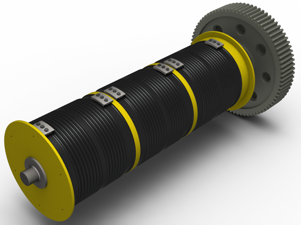
The secret to avoiding problems, whatever the application, is to get the right drum. This means having it specially designed to specifically match the structure and length of the wire rope to be used.
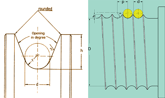
Grooving on the face of the drum is commonly used to ensure that the rope spools smoothly and tidily. Where there is just a single layer of rope on the drum, a single helical groove, like the thread of a screw, will ensure the rope travels smoothly across the drum during spooling operations.
In multi-layer applications, however, a helical groove will result in additional layers of rope lying at an angle to lower layers, crosswise, and so risk crushing lower layers. This is where Lebus grooving comes into its own. It is a special grooving pattern developed in the 1950s by Frank LeBus, an American who supplied equipment to oilfields. In 1937 he had patented the use of a groove bar to guide the spooling of rope on hoist drums and later refined this to become what he called the LeBus Counterbalanced Spooling System. Though some companies have sought to imitate the Lebus system, the original is only produced by Lebus companies in the USA, Germany and the UK.
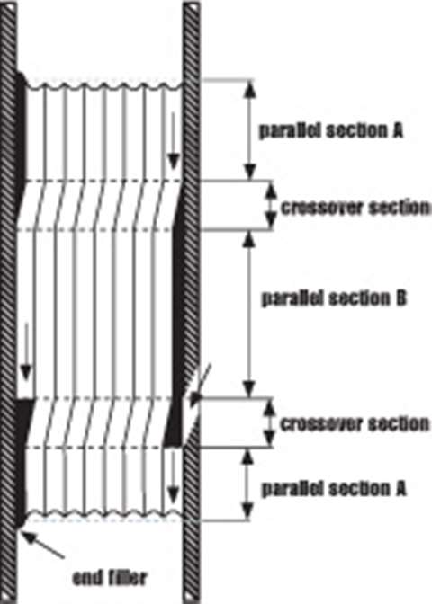
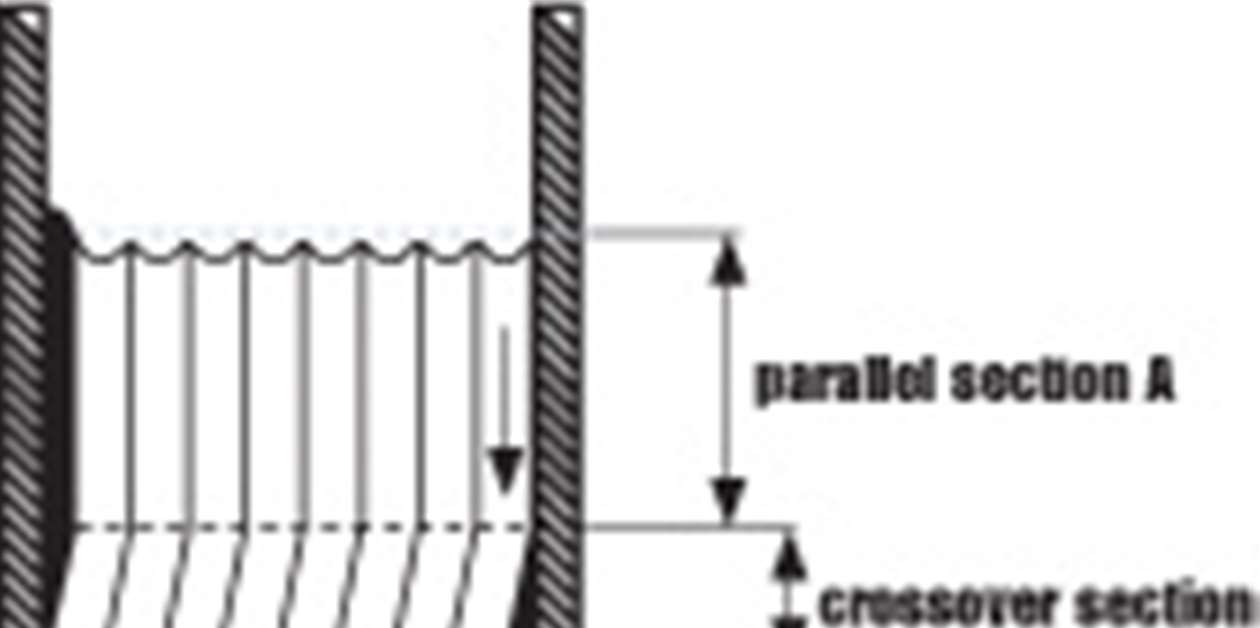
The Lebus grooving pattern has the grooves parallel to each other, and parallel to the flanges of the drum, with a crossover point on every groove on each side of the drum, (Figure 1). With this pattern, when the first layer has filled the drum, the second layer then travels back across the drum with each wrap of rope sitting precisely along the groove of two wraps of the first layer, (Figure 2).
With Lebus grooving it is possible to calculate the exact forces that the rope imposes on the drum because the spooling is totally controlled. This is not possible with any other spooling system.
Cross winding is reduced to approximately 20% of the circumference of the drum, and 80% remains parallel to the flanges in the inner layer rope groove.
This parallel grooving evenly distributes the load between the individual layers and has been shown to increase substantially – by more than 500% – tests have shown, the life of the wire rope.
Every Lebus system must be custom engineered. It is designed and produced specifically to meet the application for which it is used. The groove pattern is engineered to suit the rope"s length, diameter and construction type.
In any multi-layer spooling application it is important that when the rope is first installed on the drum, it is done so under tension to avoid any slack on inner layers that can be crushed or nicked against the groove walls by outer layers.
In general, the tighter the line, the better the spooling, but the rope should be tensioned with at least 2% of the breaking load or 10% of the working load. However, provision must also be made for the safety coefficient and the design of the cable. All subsequent spooling should also take place with the line under tension.
The fleet angle is the angle between the rope coming off the drum and the point at which it meets the first fixed sheave. Optimum fleet angle depends on the load, wire rope construction and line speed but our unrivalled experience has taught us that, as a good rule of thumb, it should generally never be any more than 1.5 degrees and no less than 0.5 degrees. Using these fleet angle guidelines means that for every 10 m that the drum is distanced from the sheave, the rope"s distance from the midpoint of the drum should never be more than 260 mm (520 mm between the flanges).
With helical grooved drums, the fleet angle can be up to 3 degrees, since the grooving is already at an angle to the flange, but only if the rope is wrapped in a single layer. If there is a second layer, such a large fleet angle will result in the rope cutting across too much and leaving gaps, which damages the rope.
When spooling a wire rope around a drum in multiple layers, the rope needs to be flexible enough to wrap tightly onto the drum, yet also sturdy, strong and rigid enough so that it does not suffer any deformation. Lebus has worked closely with all the major international wire rope manufacturers in developing optimum specifications for multi-layer applications.
Sheaves facilitate the smooth and safe operation of overhead crane hoists. Damaged sheaves can wear ropes prematurely and cause other dangerous hazards, such as binding wire rope. Konecranes technicians are trained to identify and correct problems with sheaves and other parts of hoisting equipment.
Sheaves carrying ropes which can be momentarily unloaded shall be provided with close-fitting guards or other suitable devices to guide the rope back into the groove when the load is applied again.
The sheaves in the bottom block shall be equipped with close-fitting guards that will prevent ropes from becoming fouled when the block is lying on the ground with ropes loose.
In using hoisting ropes, the crane manufacturer"s recommendation shall be followed. The rated load divided by the number of parts of rope shall not exceed 20 percent of the nominal breaking strength of the rope.
Rope clips attached with U-bolts shall have the U-bolts on the dead or short end of the rope. Spacing and number of all types of clips shall be in accordance with the clip manufacturer"s recommendation. Clips shall be drop-forged steel in all sizes manufactured commercially. When a newly installed rope has been in operation for an hour, all nuts on the clip bolts shall be retightened.
Wherever exposed to temperatures, at which fiber cores would be damaged, rope having an independent wirerope or wire-strand core, or other temperature-damage resistant core shall be used.
Replacement rope shall be the same size, grade, and construction as the original rope furnished by the crane manufacturer, unless otherwise recommended by a wire rope manufacturer due to actual working condition requirements.
Konecranes wire rope inspections can help crane users extend the life of hoist ropes. Ropes, sheaves and other reeving system components are inspected for compliance with crane standards, and to determine if they have flaws that could hinder safe operation. Contact us today to schedule an assessment.
*The foregoing OSHA regulations are not intended to be a comprehensive overview of all applicable regulations pertaining to the designated topic. State laws may mandate different safety and maintenance standards. Accordingly, please consult applicable state laws as well as original equipment manufacturer specifications for further guidance. The statements and descriptions contained herein constitute the opinion/recommendation of the seller and are not intended to create any express warranties.


 8613371530291