
wire rope encoder free sample
Empower devices to communicate alone analog or digital channels using wire rope encoder from our wholesale partners. We are ready to meet your incremental or absolute encoding needs. We"ve got software and hardware wire rope encoder for streaming as well as HD, HDMI, IP, and IPTV types. So much of our world is digital and these are the very components responsible for harnessing those signals, invisible to the naked eye, as they pass from the analog world into our integrated digital surroundings.
We have you covered whether you are supporting fully digital systems or mechanical systems communicating with the digital world. Be sure to keep absolute encoders on hand to support stable systems and incremental wire rope encoder on hand to support responsive, rapid-change systems. We have linear encoders to support mechanical application such as inkjet printers, machining tools, and semiconductors. But we also stock HD, HDMI, IP, and IPTV encoders for data streaming scenarios. In our world, data needs to keep moving, and we"ve got the wire rope encoder to help.
Act now to stock up on our wholesale quantities and competitive prices. These wire rope encoder are ready to ship to you so that your inventory is always ready for repairs or for new smart builds, from city planners and engineers, to the home hobbyist, these electrical components are fundamental to a smart, integrated digital system, machinery and devices from small to massive, and the internet of things.
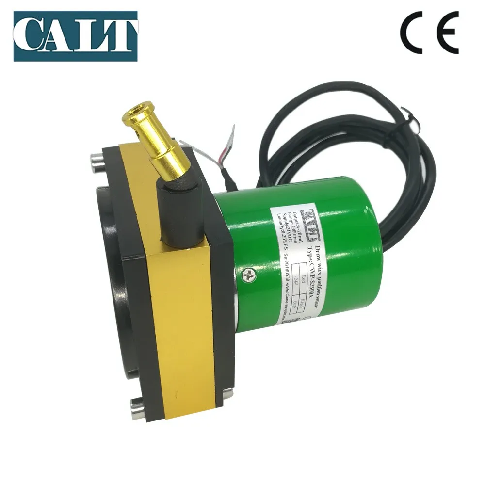
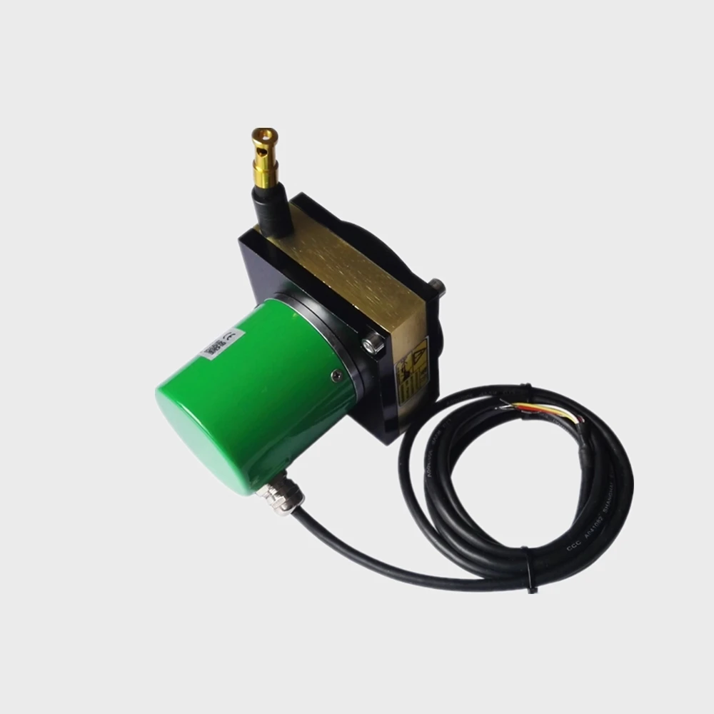
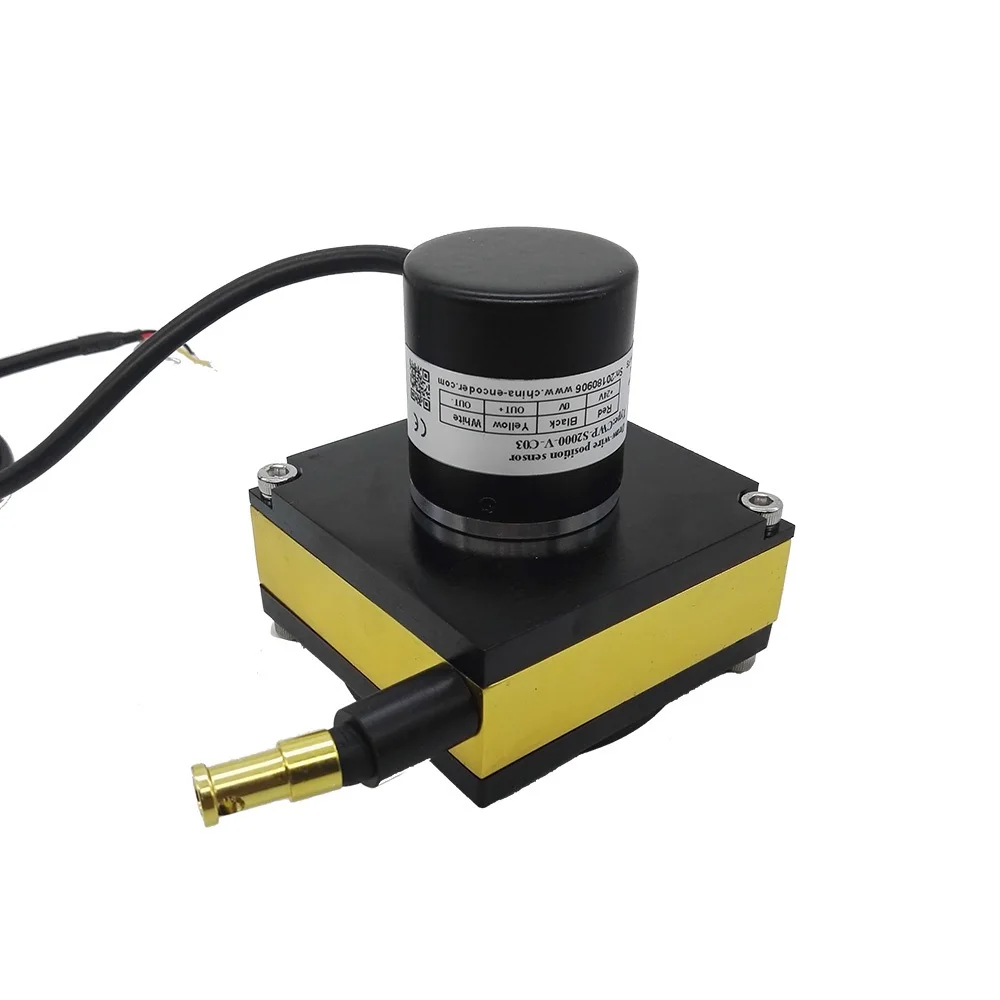
Draw-wire mechanisms for encoders are the ideal choice when positions must be accurately determined over straight distances. Examples of use range from short distances, for example with scissor lifts or fork lift trucks, to long distances, such as those covered by trolleys on crane booms or transport systems in high-bay warehouses.
Advantage of the pulley principle: there is an uninterrupted connection between the encoder and the moving object. Adverse effects on distance detection e.g. caused by dirt with optical distance measurement, are mostly eliminated. The mechanical components are designed for industrial, long-lasting use with up to 1 million pulls.

Rotary encoders inherently monitor the displacement or position but can be used to measure linear distance by calculating the number of pulses compared to the known number of pulses per arc length and designed into a system that returns linear feedback.
For a detailed discussion of distance measurement using draw-wire encoders, see the articleHow to Measure Distance with Draw Wire Encoders. Here, we focus on length-measuring applications, reviewing best practices for specifying and implementing these systems.
A measuring wheel or follower-wheel encoder consists of an encoder wheel mounted on the shaft of an encoder (or vice versa). The wheel interfaces directly with the surface of the material being measured. As the material moves relative to the encoder, the wheel turns, rotating the encoder code disc and generating a signal.
To calculate the length traveled L (inches) using the output from anincremental encoder, we start by calculating the number of pulses per 1 in. arc length (PPI):
Depending on the application, theencoder measuring wheelmay be fixed, as for a paper measuring system in a converting line or a printing line. Alternatively, the follower wheel may be in motion while the material being evaluated remains fixed. Examples of this case include roadways for paving applications or the side of a hoistway in an elevator shaft.
The most important aspect of measuring length with a measuring wheel encoder is avoiding slippage. The encoder wheel needs an adequate coefficient of friction relative to the material being evaluated. The coefficient of friction can be adjusted by a combination of the structure of the wheel surface and its materials. In the case of measuring lengths of silk fabric in a large industrial cloth-cutting operation, the wheel might be fitted with soft rubber fingers. In a hay baler, the device would use wheels fitted with long metal teeth. The spikes catch in the hay, turning to measure out the length of a bale so that the machine knows when to cut it and band it. On a machine for applying asphalt sealant to roadways, the follower wheel may simply be finished with a treaded O-ring.
A simple example of an overhung load is in a belt and pulley system. In this use case, the unit would apply a toothed follower wheel that would engage with the belt. The belt tension controls the load on the wheel: If the belt is too loose, the wheel can slip; if it is too tight, it has the potential to damage the encoder.
Another common use case would be tracking the movement of a gantry. The encoder would be mounted on the trolley with the wheel pressed against the frame.
Rack and pinion designs require care to avoid damaging the equipment or potentially compromising the measurement. Here, too, excess overhung load can damage the encoder. The problems can be more subtle than that, however. If the rack is mounted to the machine frame, it can transfer machine vibration to the encoder via the pinion. This could introduce an artifact into the data at the resonant frequency of the machine.
Even in the absence of an overhung load, problem applications abound, such as in therailroad industrywhere maintenance vehicles use follower-wheel encoders to measure track length. Follower wheels in these types of systems should be implemented with care. The encoder shaft should not carry the weight of the assembly. Depending on the condition of the equipment and the track, this arrangement can apply a high force load to the encoder shaft.
One solution is to use a dual-shaft encoder and mount a follower wheel on either side. For an application involving higher shock and vibration, a hollow-bore encoder might prove more rugged. In this implementation, a fifth wheel or idler wheel with an extended shaft is added to the vehicle and the encoder is mounted on the shaft. The bearing of the wheel assembly takes the load, saving the encoder.
Not every application enables the load to be measured directly. In destructive testing, for example, a pair of grippers are used to pull apart the test piece until it fails. In this case, the encoder is mounted on the motor shaft to track rotations. This data can be used with a variation of equation 1 and equation 2 to yield the displacement of the grippers.
Mounting the encoder on the motor shaft is a common approach. It is simpler to execute than a follower wheel, with fewer potential mounting errors. On the downside, mechanical elements like gearboxes and couplers can introduce issues such as compliance, backlash, and hysteresis. Actuators can also introduce mechanical slop as well as practical problems. Screw-type actuators with finer thread pitches have a very high number of turns per inch. This can present a challenge even for multi-turn absolute encoders.
Length measurement has a wide range of use cases, each with its own specific requirements. By taking advantage different implementations and a wide variety of encoders, engineers and maintenance staff can satisfy the needs of the application. Pay attention to these tips and followbest practices for encoder wiringand installation and your system will operate as desired.
Steel ropes and hot wire are in long lengths and at high speeds correctly cut to length. In both cases, contact measurement devices are very susceptible to wear. With sufficient material guidance, μSPEED systems reliably and permanently measure all materials and speeds.
Product Types of Laser-Encoder Length Measurement Systems and Speed Measurement SystemsBidirectional non-contact laser length measurement system for nearly any application and material movement as well as conveying processes.Smart sensor with typical measurement accuracy ± 0,05 %
Videos for the product range of laser-encoder length measurement systems and speed measurement systemsLaser-Encoder Length Measurement Systems and Speed Measurement Systems

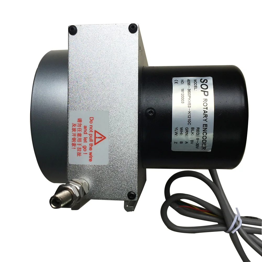
Incremental optical rotary encoders, also known as shaft encoders, are electromechanical position feedback devices. The output data they generate provides information to control systems and allows them to determine position, speed, acceleration, deceleration and travel distance in motion control applications.
An optical encoder consists of the following components: a moveable disc, an LED (Light Emitting Diode) source, a photo detector and a signal processor that converts the analog waveforms to digital waveforms.
The encoder disc, or code wheel, has a pattern of spaces, called windows, on it. When the LED light passes through one side of the disc, the photodiode detects interruptions. The photodiode creates analog signals which are processed and digitized for use by external control devices.
Rotary encoders, also known as shaft encoders or transmissive rotary encoders, are electromechanical position feedback devices. The output data they generate provides information to control systems and allows them to determine position, speed, acceleration, deceleration, and travel distance in motion control applications.
They’re called rotary encoders because they measure how far something turns (like a servo motor shaft). This measurement of distance around an axis is called angular position.
An incremental encoder is a type of rotary encoder that indicates motion and direction. Incremental encoders work by generating A/B output signals based on a specific number of pulses per rotation. In this way, the angular motion of the shaft is converted into a code (encoded) to determine its position or motion.
An incremental rotary encoder is different from an absolute rotary encoder in the type of information it measures. Incremental encoders measure change in position. Absolute encoders indicate the absolute position, which is a designated starting point. Because the absolute or “zero” position of the shaft is recorded, an absolute encoder provides position data even after a power failure, or if the shaft moves while the encoder is turned off. Incremental encoders require a reset or reference position every time they’re turned on, to locate their position in rotation.
An optical encoder is a type of rotary encoder that uses an LED light source, a photodetector (light sensor), and a moveable disc with slotted openings to generate and count light pulses as the shaft turns. Optical encoders are used to measure position, velocity, and acceleration in a variety of applications.
Optical rotary encoders are extremely precise and offer higher resolution (accuracy), making them ideal for applications like machine tools, robotics and CMMs (coordinate measuring machines).
Since 1989, Quantum Devices has been known for incremental encoder manufacturing innovation. Our full line of high performance encoders fits a wide variety of industries and applications. Buy rotary encoders online direct from our store. To find out which rotary encoder would be best for your specific application, or to request a custom configuration,


 8613371530291