
wire rope failure modes brands
In 1998, a crane load line broke while lifting the south topside module of the Petronius platform, dropping the module into the Gulf of Mexico. The cost was estimated to be around 116 million US dollars. Since 1999 more than 60 people have been killed as a result of wire ropes breaking and more than 65 associated injuries.
Not many people appreciate that there are literally thousands of wire rope designs, most of which can be put into a specific category. According to BS ISO 4309 2010 there are currently more than 25 categories of crane wire rope, each with differing characteristics and also different discard criteria. Deterioration can be measured, counted or calculated and the wire rope eventually taken out of service based on sophisticated discard criteria published in chosen standards, codes of practice or users handbooks.
Unfortunately there is no simple answer to either of these questions. All wire ropes will eventually break due to corrosion, wear or fatigue even if they are maintained and used properly. Unpredictable wire rope failures will inevitably occur, quite often when you least expect it if the discard criteria is ignored, or those using the equipment are ignorant of it.
James Dawes of Topeka, Illinois, was killed in 2008 after being struck by the boom of a Link-Belt crane; the accident was caused by the boom hoist wire rope breaking. The crane rope had been inspected, but a report said that the inspector failed to reject the rope showing a high number of visible wire breaks. Premature or unexpected wire rope failures can also be attributed to poor manufacture, incorrect handling and storage, poor installation technique, poor selection or fitting of its termination, infrequent or inadequate inspection and poor maintenance. Of course there is always the possibility that mechanical damage can occur and this is usually attributed to human error.
It is necessary, particularly during offshore operations that frequent inspections are carried out over the whole length of the working part of all steel wire ropes. The frequency of inspections should be based on the severity of use and risk assessment and particular attention should be paid to the critical areas of the wire rope; areas that are frequently running over sheaves, compensating sheaves and the rope termination to name a few.
If a wire rope has not been subjected to an abnormal environmental condition such as excessive heat, chemical attack or any corrosive solution and it has not been the victim of any form of mechanical damage, then trained operatives and inspectors can reasonably predict the length of time the steel wire rope is likely to last. That prediction, of course, will be dependent on the knowledge and experience of those making it coupled with known facts about the rope, its current condition and the application it is running on. The Inspector should be aware of the previous rope’s history, capacities of loads and the reeving systems employed together with the frequency of use etc.
Various standards and codes of practice have been written by recognized bodies and institutes based on the experience of experts or representatives of corporate organizations who have a vested interest. These standards do offer guidance on when a wire rope should be removed from service based on wear, abrasion and fatigue amongst others things, but none of these standards have any legal status except when they are called up by contract. Indeed they can all be supported or overturned in a court of law by an expert.
The users handbook, or more importantly the safe use instructions do have legal status. In many parts of the world these days, suppliers of cranes or any machinery for that matter, issue safe use instructions with new equipment. Modern applications employ modern wire rope and, in some cases, sheaves and pulleys that are made with materials other than steel. Original equipment manufacturers of such applications may impose discard criteria for the wire rope that is stricter than those in chosen standards. By law the user must follow manufacturers’ instructions.
Wire ropes will deteriorate much more quickly if they go dry and are allowed to remain in that condition. Tests have proven that a dry rope will lose up to 60 % of its expected life if it is not re-lubricated. There are differing schools of thought as to how wire rope should be lubricated. Some believe that a thin lubricant should be applied using a paintbrush. It is thought that this method allows the lubricant to penetrate. Experience has proven however, that thin penetrative lubricants will easily drain away or fly off in hot climates.
Another school of thought, and the one I stand on, is that grease should be pressure lubricated into the rope. This method, if applied properly, will ensure that the grease penetrates the rope pushing out the old lubricant with it and any possible corrosive agents such as salt water and sand. Any lubricant that is used must be compatible with the type that was applied previously and it is a good idea to consider the environment as well.
In any event, wire ropes usually announce that they are about to break. A series of individual wire breaks can be heard. These are likely to go on over several seconds and continuing for up to ten minutes before ultimate failure. Therefore, if operatives understand the warning signals, expensive incidents could be avoided.
Figure 2 shows two pieces of the same rope, the bottom portion quite clearly shows a progression of wire breaks. The operator was able to put the load down before disaster struck. The root cause of this fault was core deterioration brought about by internal corrosion.
To answer the other question on accountability, the list is extensive. Usually the first suspect is the wire rope manufacturer and that may be where the problem lies, but very often that is not the case. What if you were supplied the wrong rope for the application? Maybe you ordered the wrong rope or your buyer bought it from a cheap unapproved manufacturing source.
Perhaps your supplier is responsible, maybe he provided you with a rope that was produced to the wrong specifications. Would you know the difference? Perhaps you were sold a rope that had been stored in the suppliers or manufactures stock for a number of years and, whilst it was there, it hadn’t been properly maintained. Maybe the rope had been badly handled or installed incorrectly. The list of possibilities is endless.
In 1999 a ropeway in the French Alps snapped causing 21 deaths. In 2003, a ropeway wire rope snapped and 7 people died and a further 42 were injured. In 2007 a crane wire rope snapped at New Delhi’s metro, the entire structure tumbled down crushing workers underneath, six people were killed and 13 more were injured. In 2009 26 people were killed and 5 people were injured when a rope failed in a mine and a further 6 people were injured when a lift rope broke inside London’s Tower Bridge.
If you find yourself in the unfortunate situation after the unthinkable premature failure of a wire rope, then you might like to know that there are independent analytical services capable of determining probable cause. One of these is Doncaster Analytical Services Ltd (DAS), they have an independent metallurgical laboratory providing factual analysis and testing of wire rope for any reason (contact Mr Shui Lee, Technical Director, Tel +44(0)1302 556063, email: shui.lee@doncasteranalyticalservices. com).
You do not need a wire rope to fail in order to learn. Careful analysis of discarded ropes can also give you valuable information about your application, the way it operates, and the rope you have been using.
Based on this information, a trained, skilled and experienced inspector will be able to advise on a better crane or wire rope design, or to an improvement in maintenance procedures and safety.

Unfortunately, many phone calls into ITI Field Services begins this way, “We have had an incident with a wire rope and we believe the rope failed. How do we determine the cause of failure?”
Fortunately, the calls come in because wire rope users want to determine cause of failure in an effort to improve their crane, rigging and lifting activities.
A wire rope distributor received a hoist rope and sockets from a rubber-tired gantry. The rope and sockets were returned by the customer who believed the rope and sockets failed. The distributor hired ITI Field Services to conduct an analysis on the rope and sockets to determine the cause of the failure and to produce written documentation.
Based on the findings of the examination, fatigue-type breaks in the wires indicated that the wire rope lost significant strength due to vibration. There was no indication that the rope was overloaded. The poured sockets showed no evidence of abnormalities in the pouring method, wire zinc bonding length or the materials used in the speltering process. The conclusion of the inspection is that rope failed due to fatigue.
Wire rope examination is just one of the many services that is offered by ITI Field Services. ITI has some of the most highly-regarded subject-matter experts in the crane and rigging industry with experience in performance evaluations, litigation, accident investigations, manual development and critical lift planning reviews.
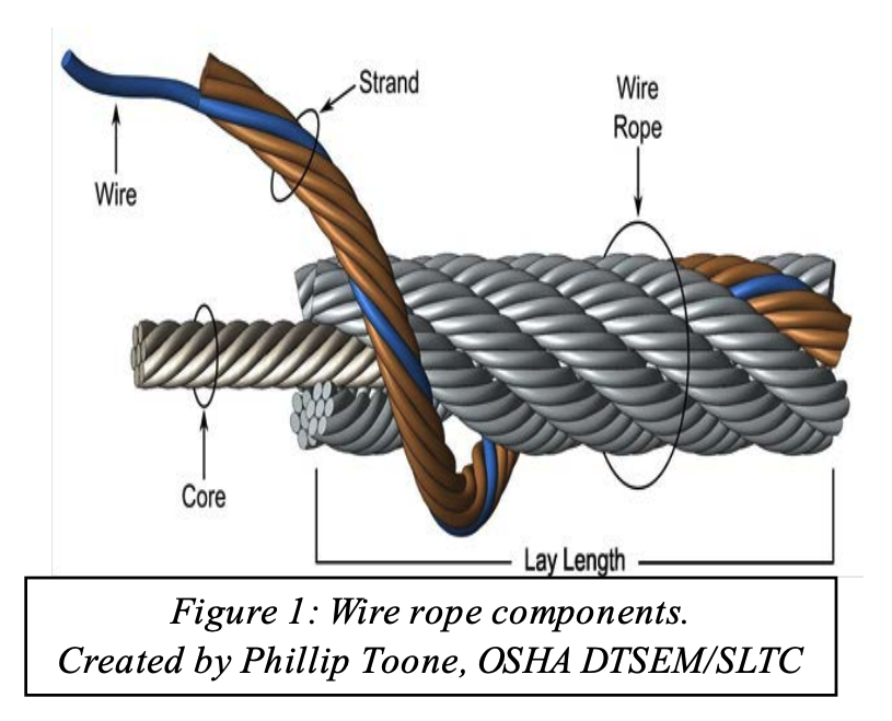
A failure analysis of a broken multi strand 71mm steel wire rope used in the main towing winch was carried out. The wire rope was failed during a bollard pull test. The wire rope was a new one and had failed during the first use. The wire rope was in IWRC/ RHO 6X41 constructions. Fig.1 shows the typical cross section of the wire rope. The failure investigation is performed by chemical and metallurgical examinations.
(ii) the uniformity and cleanliness of the microstructure of the rope steel and the effect of microstructure on crack initiation and propagation, and
1) Chemical analysis of steel wire rope is presented in Table 1. The analysis showed that it is made of high carbon steel corresponding to AISI 1074 grade, and galvanized with zinc to resist corrosion.
2) The microstructure observed under optical microscope and is shown in Figs. 2. It was typical of a drawn ferrite–pearlitic steel wire with heavily cold worked micro structure. Further examination of microstructure of the failed wires did not indicate any sign of metallurgical problems such as de- carburized layer, nonmetallic inclusions, or martensite formation. In addition, the wires were free from any sort of corrosion and pitting. Therefore, corrosion had no role in the failure of wires.
4) Table 3 represents the tensile values of the wire. The result indicates relatively less value comparing the metallographic results and the mill test certificate supplied by the Client. Figs. 3 showing Stress- Strain during tensile testing of the wire
The high hardness values, chemical composition, and the pearlitic structure of wires indicating that this is a type of extra extra improved plow steel (EEIPS) grade wire ropes. These types of wires have typically higher load-bearing capacity as compared with other grades. They are considered as heavy-duty wire ropes. The minimum tensile strength of EEIPS is 2160 N/mm2. (Ref. API Spec 9A)
5) The fractured ends of group of wires were visually inspected. Majority of wires failed in shear, and the remaining had cup-and-cone fracture, some of which are shown in Fig. 4.
Fractographs of broken wires in the form of cup and cone and shear are shown in Fig. 5 and Fig.6. Tensile overload fracture occurs when the axial load exceeds the breaking strength of the wires. This type of fracture usually appears in ductile manner, either in the form of cup and cone or in shear mode. In the former case, there is a reduction at the fracture which is called necking, whereas in the case of the latter, fracture surface is inclined at 45degree to the wire axis. In both cases, ductile dimple formations are clearly observed and confirm the tensile overloading of wires.
Every wire rope failure will be accompanied by a certain number of tensile over load breaks. The fact that tensile overload wire breaks can be found therefore necessarily mean that the rope failed because of an overload. The rope might have been weakened by fatigue breaks. The remaining wires were then no longer able to support the load, leading to tensile overload failures of these remaining wires.
Only if the metallic area of the tensile overload breaks and shear breaks combined is much higher than 50% of the wire rope’s metallic cross section is it likely that the rope failed because of an overload.
Shear breaks are caused by axial loads combined with perpendicular compression of the wire. Their break surface is inclined at about 45degree to the wire axis. The wire will fail in shear at a lower axial load than the pure tensile over load.
If a steel wire rope breaks as a consequence of jumping a layer or being wedged in, a majority of wires will exhibit the typical 45degree break surface.
In the instant case the wire rope was failed at 100 Ton or even less. As the breaking load of the wire rope is 353 Tons, there is no reason for a tensile over load breaks in an axial direction and that too considering the fact that the wire rope was failed during a bollard pull test. Fig. 7 shows the maximum stress generations in the wire rope at 100 Ton under normal bollard pull test. More over the metallurgical investigation is also not suggesting for any factors that fostering an axial overload failure.
The failure of the wire rope was studied in detail. In order to investigate the problem metallurgical and mechanical post failure analyses were performed. The wire rope was made of AISI 1074 grade steel, and it was a type of EEIPS. The microstructure was composed of severely deformed and elongated ferrite–pearlite, and no other phase formation or nonmetallic inclusions could be detected. The morphologies of fractured surfaces indicated that the wires were mainly failed in shear mode and few in tensile mode. Owing to galvanized coating, the wires were free from corrosion.
The tensile strength of the wire material is less than the required value. The required tensile strength of EEIPS is 2160 N/mm2 and the obtained value is 2059 N/mm2. But this factor is not a reason for the current failure of the wire rope. The said point is substantiated by the following:
It is concluded that the wire rope was failed due to shear breaks. Shear breaks were caused by high axial loads combined with perpendicular compression of the wire. It is worthwhile to note that the rope was failed in its first usage. The shear break is linked to the lapses during the installation/ spooling of the wire rope.
b) Lack of pretension of lower rope layers during spooling. In the absence of proper pretension the upper layers might be pulled in between the lower layers during loading.
c) Under high tension, the rope tends to be as round as possible. With no load, a rope can be deformed and flattened much easily. Highly tensioned upper layers will therefore severely damage loose (and therefore vulnerable) lower layers.
Hoisting loads with a wire rope is a simple operation. Hook it up; lift it. Turns out, it’s more complicated than it appears. The details of setting up, inspecting, and maintaining lifts with wire ropes are not complicated, but are critical. A lift that goes awry is dangerous. A bad lift puts workers at risk. In this article, we discuss the causes of wire rope failure and how to avoid them.
Abrasion breaks are caused by external factors such as coming into contact with improperly grooved sheaves and drums. Or just hitting against some object during operation. Worn, broken wire ends is the result of an abrasion break. Common causes of abrasion breaks include:
Core slippage or protrusion is caused by shock load or improper installation of the wire rope. Excessive torque can cause core slippage that forces the outer strands to shorten. The core will then protrude from the rope. Wire ropes designed to be rotation-resistant should be handled carefully so as not to disturb its lay length.
Corrosion breaks cause pitting on the individual wires that comprise the rope. This type of damage is caused by poor lubrication. However, corrosion breaks are also caused by the wire rope coming into contact with corrosive chemicals, such as acid.
There are many ways the strands of a rope can be crushed or flattened. Improper installation is a common cause. To avoid crushing, you’ll want the first layer of the wire rope to be very tight. You’ll also need to properly break-in a new wire rope. Other causes of crushing include cross winding, using a rope of the wrong diameter, or one that it too long.
Cracks to individual wires are caused by fatigue breaks. Fatigue breaks happen because the wire rope is being bent over the sheave over and over again. In time, the constant rubbing of the wire rope against the sheave or drum causes these breaks. Sheaves that are too small will accelerate fatigue breaks because they require more bending. Worn bearings and misaligned sheaves can also cause fatigue. A certain number of broken wires is acceptable. The worker responsible for equipment inspection prior to use should know the American Society of Mechanical Engineers (ASME) standard for wire ropes. The ASME standard determines whether the wire rope must be replaced. (https://www.asme.org/)
Selecting the right wire rope for the job is critical. There is never a perfect rope. For example, you will need to make a tradeoff between fatigue resistance and abrasion resistance. There are several aspects to wire rope design to consider, including:
In general, the proper wire rope will have a strength rating high enough to handle the load. (Strength is rated in tons.) It can handle the stress of repeated bending as it passes over sheaves or around drums. How you attach the rope in preparation for the lift matters and should only be handled by properly trained workers.
The wire rope (and all the equipment involved in a lift) should be fully inspected prior to the lift. The worker performing the inspection should be well-versed in the types of damage that can cause a wire rope to fail. Using a checklist is highly recommended. This will ensure that the inspection is complete. Worker and supervisor signoff will increase accountability. Of course, the wire rope must be maintained according to the manufacturer’s instructions.
How a wire rope is stored, the weather conditions in which it is used, and how they are cleaned all affect its useful life. The Occupational Safety and Health Administration (OSHA) provides these recommendations: (Source: https://www.osha.gov/dsg/guidance/slings/wire.html)
Preventing wire rope failures starts with selecting the right one for the job. When in doubt, talk with your local equipment dealer. Be prepared to discuss your specific job requirements. A thorough inspection of the wire rope prior to using it is critical. Finally, properly store your wire rope. The selection, inspection, and care of wire rope is key to job safety.
Wire ropes with diamond beads used in machines for cutting blocks of stone are subjected to fatigue, contact fatigue, corrosion and corrosion-fatigue loads in an aggressive environment.
As shown in Figure 1 1-3, multi-wire machines for cutting blocks of stone are made of two structural main components: the supporting structure, fixed with flanged bolts to the ground, (1 in Figure 1), and a vertical moving part 4 (Figure 1). Several wire ropes with diamond beads are put in motion by a driven drum (2 and 7 in Figure 1). The tensioning mechanical system (9 in Figure 1) allows to apply a tension to the wire ropes with diamond beads while the machine is cutting the stone blocks. Several pulleys guide the wire ropes; up to 80 wire ropes can be used and mounted in parallel on the structural component 4 and on several pulleys. the motorized drum is the component 3 in Figure 1 and a three-phase asynchronous electric motor is mounted on the machine and puts the drum and the wires in motion. Wire ropes with diamond beads are the cutting tools of the machine and the designer must take care of such components when mounted on the machine. It is well known that the structural behavior of steel wire ropes, composed of several strands, is complex and multiaxial stresses, along with contact fretting stresses, must be managed. Working conditions of the wire ropes have to be strictly controlled and checked periodically.
Notwithstanding there are many literature references on the study of the damage of wire ropes, few research references can be found in the literature, as far as the author knows, that would allow to understand their structural behavior in terms of damage or failure analyses 4-11. In 4 Authors report a study on the diamond wire cutting of concrete materials. Wire cutting with diamond technique was used in the United States until the early 1980s and allowed to cut reinforced concrete structures, regardless of thickness and reinforcement content. In 5 an innovative and optimized design of automatic adjustment system for beaded rope of new diamond wire sawing machine is reported, while in 6 the mechanics of sawing granite with diamond wire is considered. Research on cutting performance optimization of diamond wire saw is deepened in 7. In these papers the structural design of the wire rope with diamond beads is introduced and the mechanical structure and control of the adjusting device of the diamond wire saw are described. Working parameters are transmitted via wireless signals to achieve remote control. Mechanics of cutting procedure is deepened and mechanical simulation and optimization models of the wires with diamond beads are proposed. Many references are available on the study of wire ropes without diamond beads 8-11; such references allow to understand the mechanisms of failure in case of absence of the beads: unfortunately, the Author pf this paper found that the structural fatigue and corrosion-contact-fatigue behavior of the wire rope is highly influenced by the presence of the diamond beads.
This paper contains the results of the observation of surface damage of wires used in multi-wire machines for cutting blocks of stone and the optical analysis of beads for 2.35 mm cables. The cables are used as a support for pearls equipped with diamond inserts for cutting stones (beads) (Figure 2).
The samples were taken from wire ropes having 2,35 mm diameter. The wire rope is composed of 7 strands wires, one of which is located at the centre of the wire rope (“soul”). Each strand contains 7 single wires having 0.3 mm wires diameter (Figure 5).
Significant sections of the beaded wire as shown in Figure 4 were investigated. Section X.1 was not considered but we focused on the evaluation of the centering of the cable in the beads. The sections were obtained using a metallographic cutting machine.
The wire ropes with beads were also observed by unwinding the strands and the core both by opening the individual strands and by releasing the individual wires before proceeding with the observation. Figure 5 shows two examples of preparation of a stranded cable and single strands and wires.
Figure 6 shows two examples of the cracked surfaces of the wires. Those cracks greatly affect the fatigue resistance of the whole wire rope with beads.
To evaluate the effect of the environment on the wire rope, tests were carried out with penetrating liquids (blue ink). Liquids were poured onto the flexed sample to simulate operational behavior. Figure 8 shows the penetrating liquids experimental test.
Contact between the wire rope and the beads was observed (Figure 9). Beads and the wire rope are made of different materials and this might cause corrosion of the wires in the rope, along with contact fatigue damage.
The wire ropes studied in this work are designed with low fatigue resistance safety factors (2-3). Previous analyses helped in reaching some useful conclusions 3-10.
Detachment of brass or zinc coatings which, being thin, are unable to adhere to the wire at the cracks. Causes can also be found in the straightening operation and incorrect handling of the ropes.
Observations and analysis of the damaged wire ropes allowed to highlight that the beads have no continuous side surface and at the discontinuity the finish is very poor. Moreover the insertion of the diamond chips is not uniform. The insertion of the splinters causes localized lifting of the material. This could cause premature detachment of some of them. Wire ropes are mechanical components that work in a complex stress state with contact loads, wear, corrosion and fatigue resistance problems. The presence of the diamond beads is a further stress concentration, with corrosion and contact wear fatigue problems if the beads come into contact with the wire rope during assembly or in working condition.
The advice is to product wire ropes with beads in which the centering of the cable with respect to the bead is carefully controlled. No contact between rope and bead should occur. According to the results and observations this is the most important advice for producer of the ropes with diamond beads.
This paper reports the failure analysis of the damage mechanisms of wire ropes with diamond beads mounted in machines for cutting stones. Wire ropes with diamond bead are cutting tools subjected to fatigue, corrosion-contact-fatigue stresses. Cracks and defects are present in the strands of the wire ropes, generated during the production process: these cracks are further sources of stress concentrations. The observation at the microscope, and the penetrating liquids analyses, highlighted that the most important advice to give to the producer of the wire ropes with diamond beads is to product components in which the centering of the cable with respect to the bead is carefully controlled.
Pedrini, G., Baragetti, S., 2016, “Multi-wire machine for cutting blocks of stone and wire tensioning device”, International Patent n° WO 2016/071936A1.
Bangju Wei et al, 2020, “Innovative and optimized design of automatic adjustment system for beaded rope of new diamond wire sawing machine”IOP Conf. Ser.: Mater. Sci. Eng. 892 012078.
Janusz Stefan Konstanty, 2021,”The mechanics of sawing granite with diamond wire”, The International Journal of Advanced Manufacturing Technology (2021) 116:2591–2597.
Liu S., Sun Y.Send mail to Sun Y., Jiang X., Kang Y., 2022, “A new MFL imaging and quantitative nondestructive evaluation method in wire rope defect detection”, Mechanical Systems and Signal Processing, vol. 163.
Peng, Y., Wang, G., Zhu, Z., Jiang, F., Chen, G., 2021, “Effect of low temperature on tribological characteristics and wear mechanism of wire rope”, Tribology International, vol. 164.
Wang et Ali, 2021, “Tribological properties and residual strength of wire rope with different strands during the interlayer-transition stage”, vol. 480-481, Wear.
Bassir Y., et Ali, 2021, “Comparative study of the service life of a central core and a helical strand constituting the same rope”, vol. 247, Engineering Structures.
The following is a fairly comprehensive listing of critical inspection factors. It is not, however, presented as a substitute for an experienced inspector. It is rather a user’s guide to the accepted standards by which wire ropes must be judged. Use the outline to skip to specific sections:
Rope abrades when it moves through an abrasive medium or over drums and sheaves. Most standards require that rope is to be removed if the outer wire wear exceeds 1/3 of the original outer wire diameter. This is not easy to determine, and discovery relies upon the experience gained by the inspector in measuring wire diameters of discarded ropes.
All ropes will stretch when loads are initially applied. As a rope degrades from wear, fatigue, etc. (excluding accidental damage), continued application of a load of constant magnitude will produce incorrect varying amounts of rope stretch.
Initial stretch, during the early (beginning) period of rope service, caused by the rope adjustments to operating conditions (constructional stretch).
Following break-in, there is a long period—the greatest part of the rope’s service life—during which a slight increase in stretch takes place over an extended time. This results from normal wear, fatigue, etc.
Thereafter, the stretch occurs at a quicker rate. This means that the rope has reached the point of rapid degradation: a result of prolonged subjection to abrasive wear, fatigue, etc. This second upturn of the curve is a warning indicating that the rope should soon be removed.
In the past, whether or not a rope was allowed to remain in service depended to a great extent on the rope’s diameter at the time of inspection. Currently, this practice has undergone significant modification.
Previously, a decrease in the rope’s diameter was compared with published standards of minimum diameters. The amount of change in diameter is, of course, useful in assessing a rope’s condition. But, comparing this figure with a fixed set of values can be misleading.
As a matter of fact, all ropes will show a significant reduction in diameter when a load is applied. Therefore, a rope manufactured close to its nominal size may, when it is subjected to loading, be reduced to a smaller diameter than that stipulated in the minimum diameter table. Yet under these circumstances, the rope would be declared unsafe although it may, in actuality, be safe.
As an example of the possible error at the other extreme, we can take the case of a rope manufactured near the upper limits of allowable size. If the diameter has reached a reduction to nominal or slightly below that, the tables would show this rope to be safe. But it should, perhaps, be removed.
Today, evaluations of the rope diameter are first predicated on a comparison of the original diameter—when new and subjected to a known load—with the current reading under like circumstances. Periodically, throughout the life of the rope, the actual diameter should be recorded when the rope is under equivalent loading and in the same operating section. This procedure, if followed carefully, reveals a common rope characteristic: after an initial reduction, the diameter soon stabilizes. Later, there will be a continuous, albeit small, decrease in diameter throughout its life.
Deciding whether or not a rope is safe is not always a simple matter. A number of different but interrelated conditions must be evaluated. It would be dangerously unwise for an inspector to declare a rope safe for continued service simply because its diameter had not reached the minimum arbitrarily established in a table if, at the same time, other observations lead to an opposite conclusion.
Corrosion, while difficult to evaluate, is a more serious cause of degradation than abrasion. Usually, it signifies a lack of lubrication. Corrosion will often occur internally before there is any visible external evidence on the rope surface.
Pitting of wires is a cause for immediate rope removal. Not only does it attack the metal wires, but it also prevents the rope’s component parts from moving smoothly as it is flexed. Usually, a slight discoloration because of rusting merely indicates a need for lubrication.
Severe rusting, on the other hand, leads to premature fatigue failures in the wires necessitating the rope’s immediate removal from service. When a rope shows more than one wire failure adjacent to a terminal fitting, it should be removed immediately. To retard corrosive deterioration, the rope should be kept well lubricated with a clear wire rope lube that can penetrate between strands. In situations where extreme corrosive action can occur, it may be necessary to use galvanized wire rope.
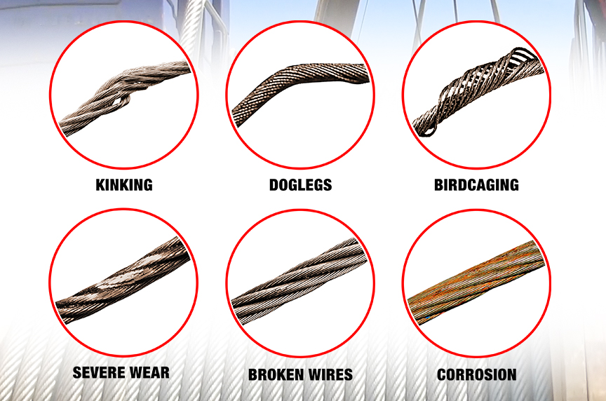
Kinks are tightened loops with permanent strand distortion that result from improper handling when a rope is being installed or while in service. A kink happens when a loop is permitted to form and then is pulled down tight, causing permanent distortion of the strands. The damage is irreparable and the sling must be taken out of service.
Doglegs are permanent bends caused by improper use or handling. If the dogleg is severe, the sling must be removed from service. If the dogleg is minor, exhibiting no strand distortion and cannot be observed when the sling is under tension, the area of the minor dogleg should be marked for observation and the sling can remain in service.
Bird caging results from torsional imbalance that comes about because of mistreatment, such as sudden stops, the rope being pulled through tight sheaves, or wound on too small a drum. This is cause for rope replacement unless the affected section can be removed.
Particular attention must be paid to wear at the equalizing sheaves. During normal operations, this wear is not visible. Excessive vibration or whip can cause abrasion and/or fatigue. Drum cross-over and flange point areas must be carefully evaluated. All end fittings, including splices, should be examined for worn or broken wires, loose or damaged strands, cracked fittings, worn or distorted thimbles and tucks of strands.
After a fire or the presence of elevated temperatures, there may be metal discoloration or an apparent loss of internal lubrication. Fiber core ropes are particularly vulnerable. Under these circumstances the rope should be replaced.
Continuous pounding is one of the causes of peening. This can happen when the rope strikes against an object, such as some structural part of the machine, or it beats against a roller or it hits itself. Often, this can be avoided by placing protectors between the rope and the object it is striking.
Another common cause of peening is continuous working-under high loads—over a sheave or drum. Where peening action cannot be controlled, it is necessary to have more frequent inspections and to be ready for earlier rope replacement.
Below are plain views and cross-sections show effects of abrasion and peening on wire rope. Note that a crack has formed as a result of heavy peening.
Scrubbing refers to the displacement of wires and strands as a result of rubbing against itself or another object. This, in turn, causes wear and displacement of wires and strands along one side of the rope. Corrective measures should be taken as soon as this condition is observed.
Wires that break with square ends and show little surface wear have usually failed as a result of fatigue. Such fractures can occur on the crown of the strands or in the valleys between the strands where adjacent strand contact exists. In almost all cases, these failures are related to bending stresses or vibration.
If diameter of the sheaves, rollers or drum cannot be increased, a more flexible rope should be used. But, if the rope in use is already of maximum flexibility, the only remaining course that will help prolong its service life is to move the rope through the system by cutting off the dead end. By moving the rope through the system, the fatigued sections are moved to less fatiguing areas of the reeving.
The number of broken wires on the outside of a wire rope are an index of its general condition, and whether or not it must be considered for replacement. Frequent inspection will help determine the elapsed time between breaks. Ropes should be replaced as soon as the wire breakage reaches the numbers given in the chart below. Such action must be taken without regard to the type of fracture.
* All ropes in the above applications—one outer wire broken at the point of contact with the core that has worked its way out of the rope structure and protrudes or loops out of the rope structure. Additional inspection of this section is required.
Rope that has either been in contact with a live power line or been used as “ground” in an electric welding circuit, will have wires that are fused, discolored and/or annealed and must be removed.
On occasion, a single wire will break shortly after installation. However, if no other wires break at that time, there is no need for concern. On the other hand, should more wires break, the cause should be carefully investigated.
On any application, valley breaks—where the wire fractures between strands—should be given serious attention. When two or more such fractures are found, the rope should be replaced immediately. (Note, however, that no valley breaks are permitted in elevator ropes.)
It is good to remember that once broken wires appear—in a rope operating under normal conditions—a good many more will show up within a relatively short period. Attempting to squeeze the last measure of service from a rope beyond the allowable number of broken wires (refer to table on the next page) will create an intolerably hazardous situation.
Recommended retirement criteria for all Rotation Resistant Ropes are 2 broken wires in 6 rope diameters or 4 broken wires in 30 rope diameters (i.e. 6 rope diameters for a 1″ diameter rope = 6″).
Distortion of Rotation Resistant Ropes, as shown below, can be caused by shock load / sudden load release and/or induced torque, and is the reason for immediate removal from service.


 8613371530291