
wire rope failure osha supplier
A competent person must begin a visual inspection prior to each shift the equipment is used, which must be completed before or during that shift. The inspection must consist of observation of wire ropes (running and standing) that are likely to be in use during the shift for apparent deficiencies, including those listed in paragraph (a)(2) of this section. Untwisting (opening) of wire rope or booming down is not required as part of this inspection.
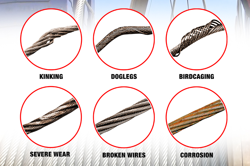
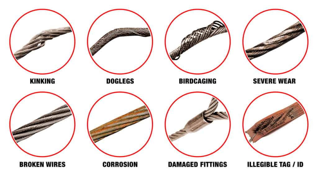
Significant distortion of the wire rope structure such as kinking, crushing, unstranding, birdcaging, signs of core failure or steel core protrusion between the outer strands.
In running wire ropes: Six randomly distributed broken wires in one rope lay or three broken wires in one strand in one rope lay, where a rope lay is the length along the rope in which one strand makes a complete revolution around the rope.
In rotation resistant ropes: Two randomly distributed broken wires in six rope diameters or four randomly distributed broken wires in 30 rope diameters.
In pendants or standing wire ropes: More than two broken wires in one rope lay located in rope beyond end connections and/or more than one broken wire in a rope lay located at an end connection.
If a deficiency in Category I (see paragraph (a)(2)(i) of this section) is identified, an immediate determination must be made by the competent person as to whether the deficiency constitutes a safety hazard. If the deficiency is determined to constitute a safety hazard, operations involving use of the wire rope in question must be prohibited until:
If the deficiency is localized, the problem is corrected by severing the wire rope in two; the undamaged portion may continue to be used. Joining lengths of wire rope by splicing is prohibited. If a rope is shortened under this paragraph, the employer must ensure that the drum will still have two wraps of wire when the load and/or boom is in its lowest position.
If a deficiency in Category II (see paragraph (a)(2)(ii) of this section) is identified, operations involving use of the wire rope in question must be prohibited until:
The employer complies with the wire rope manufacturer"s established criterion for removal from service or a different criterion that the wire rope manufacturer has approved in writing for that specific wire rope (see § 1926.1417),
If the deficiency is localized, the problem is corrected by severing the wire rope in two; the undamaged portion may continue to be used. Joining lengths of wire rope by splicing is prohibited. If a rope is shortened under this paragraph, the employer must ensure that the drum will still have two wraps of wire when the load and/or boom is in its lowest position.
If the deficiency (other than power line contact) is localized, the problem is corrected by severing the wire rope in two; the undamaged portion may continue to be used. Joining lengths of wire rope by splicing is prohibited. Repair of wire rope that contacted an energized power line is also prohibited. If a rope is shortened under this paragraph, the employer must ensure that the drum will still have two wraps of wire when the load and/or boom is in its lowest position.
Where a wire rope is required to be removed from service under this section, either the equipment (as a whole) or the hoist with that wire rope must be tagged-out, in accordance with § 1926.1417(f)(1), until the wire rope is repaired or replaced.
Wire ropes on equipment must not be used until an inspection under this paragraph demonstrates that no corrective action under paragraph (a)(4) of this section is required.
At least every 12 months, wire ropes in use on equipment must be inspected by a qualified person in accordance with paragraph (a) of this section (shift inspection).
The inspection must be complete and thorough, covering the surface of the entire length of the wire ropes, with particular attention given to all of the following:
Exception: In the event an inspection under paragraph (c)(2) of this section is not feasible due to existing set-up and configuration of the equipment (such as where an assist crane is needed) or due to site conditions (such as a dense urban setting), such inspections must be conducted as soon as it becomes feasible, but no longer than an additional 6 months for running ropes and, for standing ropes, at the time of disassembly.
If the deficiency is localized, the problem is corrected by severing the wire rope in two; the undamaged portion may continue to be used. Joining lengths of wire rope by splicing is prohibited. If a rope is shortened under this paragraph, the employer must ensure that the drum will still have two wraps of wire when the load and/or boom is in its lowest position.
Original equipment wire rope and replacement wire rope must be selected and installed in accordance with the requirements of this section. Selection of replacement wire rope must be in accordance with the recommendations of the wire rope manufacturer, the equipment manufacturer, or a qualified person.
Wire rope design criteria: Wire rope (other than rotation resistant rope) must comply with either Option (1) or Option (2) of this section, as follows:
Option (1). Wire rope must comply with section 5-1.7.1 of ASME B30.5-2004 (incorporated by reference, see § 1926.6) except that section"s paragraph (c) must not apply.
Option (2). Wire rope must be designed to have, in relation to the equipment"s rated capacity, a sufficient minimum breaking force and design factor so that compliance with the applicable inspection provisions in § 1926.1413 will be an effective means of preventing sudden rope failure.
Type I rotation resistant wire rope ("Type I"). Type I rotation resistant rope is stranded rope constructed to have little or no tendency to rotate or, if guided, transmits little or no torque. It has at least 15 outer strands and comprises an assembly of at least three layers of strands laid helically over a center in two operations. The direction of lay of the outer strands is opposite to that of the underlying layer.
Type II rotation resistant wire rope ("Type II"). Type II rotation resistant rope is stranded rope constructed to have significant resistance to rotation. It has at least 10 outer strands and comprises an assembly of two or more layers of strands laid helically over a center in two or three operations. The direction of lay of the outer strands is opposite to that of the underlying layer.
Type III rotation resistant wire rope ("Type III"). Type III rotation resistant rope is stranded rope constructed to have limited resistance to rotation. It has no more than nine outer strands, and comprises an assembly of two layers of strands laid helically over a center in two operations. The direction of lay of the outer strands is opposite to that of the underlying layer.
Type I must have an operating design factor of no less than 5, except where the wire rope manufacturer and the equipment manufacturer approves the design factor, in writing.
A qualified person must inspect the rope in accordance with § 1926.1413(a). The rope must be used only if the qualified person determines that there are no deficiencies constituting a hazard. In making this determination, more than one broken wire in any one rope lay must be considered a hazard.
Each lift made under § 1926.1414(e)(3) must be recorded in the monthly and annual inspection documents. Such prior uses must be considered by the qualified person in determining whether to use the rope again.
Rotation resistant ropes may be used as boom hoist reeving when load hoists are used as boom hoists for attachments such as luffing attachments or boom and mast attachment systems. Under these conditions, all of the following requirements must be met:
The requirements in ASME B30.5-2004 sections 5-1.3.2(a), (a)(2) through (a)(4), (b) and (d) (incorporated by reference, see § 1926.6) except that the minimum pitch diameter for sheaves used in multiple rope reeving is 18 times the nominal diameter of the rope used (instead of the value of 16 specified in section 5-1.3.2(d)).
The operating design factor for these ropes must be the total minimum breaking force of all parts of rope in the system divided by the load imposed on the rope system when supporting the static weights of the structure and the load within the equipment"s rated capacity.
Wire rope clips used in conjunction with wedge sockets must be attached to the unloaded dead end of the rope only, except that the use of devices specifically designed for dead-ending rope in a wedge socket is permitted.
Prior to cutting a wire rope, seizings must be placed on each side of the point to be cut. The length and number of seizings must be in accordance with the wire rope manufacturer"s instructions.
Scope. This section applies to slings used in conjunction with other material handling equipment for the movement of material by hoisting, in employments covered by this part. The types of slings covered are those made from alloy steel chain, wire rope, metal mesh, natural or synthetic fiber rope (conventional three strand construction), and synthetic web (nylon, polyester, and polypropylene).
Cable laid endless sling-mechanical joint is a wire rope sling made endless by joining the ends of a single length of cable laid rope with one or more metallic fittings.
Cable laid grommet-hand tucked is an endless wire rope sling made from one length of rope wrapped six times around a core formed by hand tucking the ends of the rope inside the six wraps.
Cable laid rope sling-mechanical joint is a wire rope sling made from a cable laid rope with eyes fabricated by pressing or swaging one or more metal sleeves over the rope junction.
Master link or gathering ring is a forged or welded steel link used to support all members (legs) of an alloy steel chain sling or wire rope sling. (See Fig. N-184-3.)
Diagram indicates Forms of Hitch and Kind of Sling. Eye&Eye Vertical Hitch. Eye&Eye Choker Hitch. Eye&Eye Basket Hitch (Alterates have identical load rations). Endless Vertical Hitch. Endless Choker Hitch. Endless Basket Hitch (Alternateve have identical load ratings). Notes: Angles 5 deg or less from the veritcal may be considered vertical angles. For slings with legs more than 5 deg off vertical, the actual angle as shown in Figure N-184-5 must be considered. Explanation of Symbols: Minimum Diameter of Curvature. Represents a contact surface which shall have a diameter of curvature at least double the diameter of the rope from which the sling is made. Represents a contact surface which shall have a diameter of curvature at least 8 times the diameter of the rope. Represents a load in a choker hitch and illustrates the rotary force on the load and/or the slippage of the rope in contact with the load. Diameter of curvature of load surface shall be at least double the diameter of the rope.
Strand laid endless sling-mechanical joint is a wire rope sling made endless from one length of rope with the ends joined by one or more metallic fittings.
Strand laid grommet-hand tucked is an endless wire rope sling made from one length of strand wrapped six times around a core formed by hand tucking the ends of the strand inside the six wraps.
Strand laid rope is a wire rope made with strands (usually six or eight) wrapped around a fiber core, wire strand core, or independent wire rope core (IWRC).
Sling use. Employers must use only wire-rope slings that have permanently affixed and legible identification markings as prescribed by the manufacturer, and that indicate the recommended safe working load for the type(s) of hitch(es) used, the angle upon which it is based, and the number of legs if more than one.
Cable laid and 6 × 19 and 6 × 37 slings shall have a minimum clear length of wire rope 10 times the component rope diameter between splices, sleeves or end fittings.
Safe operating temperatures. Fiber core wire rope slings of all grades shall be permanently removed from service if they are exposed to temperatures in excess of 200 °F. When nonfiber core wire rope slings of any grade are used at temperatures above 400 °F or below minus 60 °F, recommendations of the sling manufacturer regarding use at that temperature shall be followed.
Sling use. Employers must use natural and synthetic fiber-rope slings that have permanently affixed and legible identification markings stating the rated capacity for the type(s) of hitch(es) used and the angle upon which it is based, type of fiber material, and the number of legs if more than one.
Safe operating temperatures. Natural and synthetic fiber rope slings, except for wet frozen slings, may be used in a temperature range from minus 20 °F to plus 180 °F without decreasing the working load limit. For operations outside this temperature range and for wet frozen slings, the sling manufacturer"s recommendations shall be followed.
Splicing. Spliced fiber rope slings shall not be used unless they have been spliced in accordance with the following minimum requirements and in accordance with any additional recommendations of the manufacturer:
In manila rope, eye splices shall consist of at least three full tucks, and short splices shall consist of at least six full tucks, three on each side of the splice center line.
In synthetic fiber rope, eye splices shall consist of at least four full tucks, and short splices shall consist of at least eight full tucks, four on each side of the center line.
Strand end tails shall not be trimmed flush with the surface of the rope immediately adjacent to the full tucks. This applies to all types of fiber rope and both eye and short splices. For fiber rope under one inch in diameter, the tail shall project at least six rope diameters beyond the last full tuck. For fiber rope one inch in diameter and larger, the tail shall project at least six inches beyond the last full tuck. Where a projecting tail interferes with the use of the sling, the tail shall be tapered and spliced into the body of the rope using at least two additional tucks (which will require a tail length of approximately six rope diameters beyond the last full tuck).
Removal from service. Natural and synthetic fiber rope slings shall be immediately removed from service if any of the following conditions are present:

Thank you for your inquiry of January 4, requesting clarification of the Occupational Safety and Health Administration (OSHA) standards at 29 CFR 1910.184(f)(5) which gives removal from service criteria for wire rope slings. We apologize for the delay in response.
The OSHA standards at 29 CFR 1910.184(f)(5)(i) and 29 CFR 1910.184(f)(5)(ii) require wire rope slings to be removed from service immediately when the following conditions are found:
The following method may be used to determine whether the wire rope sling must be removed from service as required by 29 CFR 1910.184(f)(5)(ii). The outside individual wires are not separated from the wire rope to make them available for measuring. To measure the wear or scraping of one-third the original diameter must be measured with a micrometer at the worn or scraped area and compared to the original diameter of whole wire rope. If the difference of this measurement is equal to, or more than, one-third the original diameter of an individual outside wire, the wire rope sling must be removed from service.
OSHA will allow a wire rope to be left in service with respect to a pass/fail gage measurement if the difference between the original diameter of the whole wire rope and a pass/fail gage OD failed measurement is less than one-third the original diameter of the outside individual wire.
Mishandling of workplace materials is the single largest cause of accidents in the workplace. Fortunately, most of these accidents are avoidable. With wire rope slings playing an important role with cranes, derricks, and hoists, it’s important to understand how to make a proper selection.
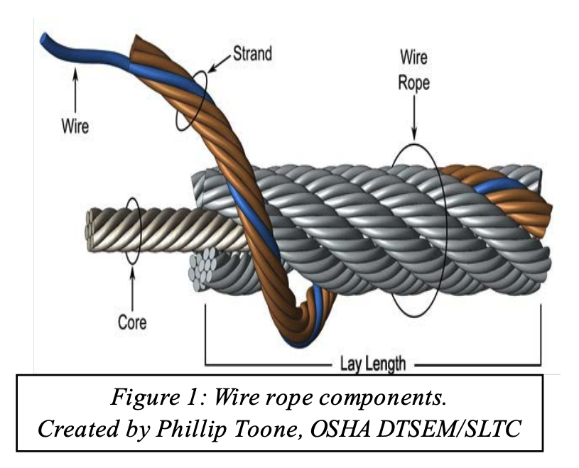
A wire rope sling is made of wire rope. It is composed of single wires that have been twisted into strands. These strands are then twisted to form a wire rope.
The strength of a wire rope sling is a function of size, grade, and construction. It needs to accommodate the applied maximum load. The more a sling is used, both the design and the sling’s strength are reduced. A sling loaded beyond it strength will fail. For older slings it’s important to inspect often.
Wire rope slings must be able to take repeated bending without wires failing due to fatigue, sometimes called bending without failure. The best way to preventing fatigue failure is to use blocking or padding to increase the radius of bend.
The ability of wire rope to withstand abrasion. It’s determined by size, number of wires, and construction of the rope. Remember that smaller wires bend easier and offer greater flexibility, which also means they are more susceptible to abrasion.
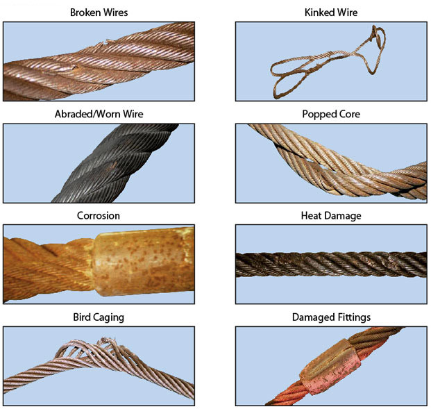
The misuse of a wire rope will cause the sling to be unsafe well before any other reason. Kinking or bird caging will reduce the strength of a wire rope. Bird caging is forcibly untwisting the wire rope strands and they become spread outward. Be sure to keep up proper use per the manufacturer specifications.
These are just four factors to consider when determining the best wire rope slings for your application. Keep in mind that weight, size, flexibility, and shape of the loads being handled will also affect the life of a wire rope sling.
Maintain a record for each rope that includes the date of inspection, type of inspection, the name of the person who performed the inspection, and inspection results.
Use the "rag-and-visual" method to check for external damage. Grab the rope lightly and with a rag or cotton cloth, move the rag slowly along the wire. Broken wires will often "porcupine" (stick out) and these broken wires will snag on the rag. If the cloth catches, stop and visually assess the rope. It is also important to visually inspect the wire (without a rag). Some wire breaks will not porcupine.
Measure the rope diameter. Compare the rope diameter measurements with the original diameter. If the measurements are different, this change indicates external and/or internal rope damage.
Visually check for abrasions, corrosion, pitting, and lubrication inside the rope. Insert a marlin spike beneath two strands and rotate to lift strands and open rope.
Assess the condition of the rope at the section showing the most wear. Discard a wire rope if you find any of the following conditions:In running ropes (wound on drums or passed over sheaves), 6 or more broken wires in one rope lay length; 3 or more broken wires in one strand in one rope lay. (One rope lay is the distance necessary to complete one turn of the strand around the diameter of the rope.)
Corrosion from lack of lubrication and exposure to heat or moisture (e.g., wire rope shows signs of pitting). A fibre core rope will dry out and break at temperatures above 120°C (250°F).
Kinks from the improper installation of new rope, the sudden release of a load or knots made to shorten a rope. A kink cannot be removed without creating a weak section. Discarding kinked rope is best.
Hoisting loads with a wire rope is a simple operation. Hook it up; lift it. Turns out, it’s more complicated than it appears. The details of setting up, inspecting, and maintaining lifts with wire ropes are not complicated, but are critical. A lift that goes awry is dangerous. A bad lift puts workers at risk. In this article, we discuss the causes of wire rope failure and how to avoid them.
Abrasion breaks are caused by external factors such as coming into contact with improperly grooved sheaves and drums. Or just hitting against some object during operation. Worn, broken wire ends is the result of an abrasion break. Common causes of abrasion breaks include:
Core slippage or protrusion is caused by shock load or improper installation of the wire rope. Excessive torque can cause core slippage that forces the outer strands to shorten. The core will then protrude from the rope. Wire ropes designed to be rotation-resistant should be handled carefully so as not to disturb its lay length.
Corrosion breaks cause pitting on the individual wires that comprise the rope. This type of damage is caused by poor lubrication. However, corrosion breaks are also caused by the wire rope coming into contact with corrosive chemicals, such as acid.
There are many ways the strands of a rope can be crushed or flattened. Improper installation is a common cause. To avoid crushing, you’ll want the first layer of the wire rope to be very tight. You’ll also need to properly break-in a new wire rope. Other causes of crushing include cross winding, using a rope of the wrong diameter, or one that it too long.
Cracks to individual wires are caused by fatigue breaks. Fatigue breaks happen because the wire rope is being bent over the sheave over and over again. In time, the constant rubbing of the wire rope against the sheave or drum causes these breaks. Sheaves that are too small will accelerate fatigue breaks because they require more bending. Worn bearings and misaligned sheaves can also cause fatigue. A certain number of broken wires is acceptable. The worker responsible for equipment inspection prior to use should know the American Society of Mechanical Engineers (ASME) standard for wire ropes. The ASME standard determines whether the wire rope must be replaced. (https://www.asme.org/)
Selecting the right wire rope for the job is critical. There is never a perfect rope. For example, you will need to make a tradeoff between fatigue resistance and abrasion resistance. There are several aspects to wire rope design to consider, including:
In general, the proper wire rope will have a strength rating high enough to handle the load. (Strength is rated in tons.) It can handle the stress of repeated bending as it passes over sheaves or around drums. How you attach the rope in preparation for the lift matters and should only be handled by properly trained workers.
The wire rope (and all the equipment involved in a lift) should be fully inspected prior to the lift. The worker performing the inspection should be well-versed in the types of damage that can cause a wire rope to fail. Using a checklist is highly recommended. This will ensure that the inspection is complete. Worker and supervisor signoff will increase accountability. Of course, the wire rope must be maintained according to the manufacturer’s instructions.
How a wire rope is stored, the weather conditions in which it is used, and how they are cleaned all affect its useful life. The Occupational Safety and Health Administration (OSHA) provides these recommendations: (Source: https://www.osha.gov/dsg/guidance/slings/wire.html)
Preventing wire rope failures starts with selecting the right one for the job. When in doubt, talk with your local equipment dealer. Be prepared to discuss your specific job requirements. A thorough inspection of the wire rope prior to using it is critical. Finally, properly store your wire rope. The selection, inspection, and care of wire rope is key to job safety.
All wire ropes will wear out eventually and gradually lose work capability throughout their service life. That"s why periodic inspections are critical. Applicable industry standards such as ASME B30.2 for overhead and gantry cranes or federal regulations such as OSHA refer to specific inspection criteria for varied applications.
You should thoroughly inspect all wire ropes at regular intervals. The longer it has been in service or, the more severe the service, the more thoroughly and frequently it should be inspected. Be sure to maintain records of each inspection.
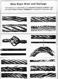
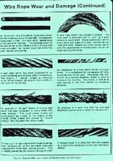
Inspections should be carried out by a person who has learned through specialized training or practical experience of what to look for and who knows how to judge the importance of any abnormal conditions they may discover. It is the inspector"s responsibility to obtain and follow the proper inspection criteria for each application inspected.
Figure 1is what happens when a wire breaks under tensile load exceeding its strength. It"s typically recognized by the "cup and cone" appearance at the point of failure. The necking down of the wire at the point of failure to form the cup and cone indicates failure has occurred while the wire retained its ductility (the ability to change form without breaking).
Figure 2is a wire with a clear fatigue break. It is identified by the square end perpendicular to the wire. This break was produced by a torsion machine that"s used to measure the ductility. This break is similar to wire failures in the field caused by fatigue.
Figure 3 is a wire rope that has been subjected to repeated bending over sheaves under typical loads. This fatigue results in breaks in individual wires - these breaks are square and usually in the crown of the strands.
Figure 4 is an example of fatigue failure of a wire rope subjected to heavy loads over small sheaves. The breaks in the valleys of the strands are caused by "strand nicking." There may be crown breaks, too.
Figure 5 is a single strand removed from a wire rope subjected to "strand nicking." This condition is a result of adjacent strands rubbing against one another. While this is normal in a rope"s operation, the nicking can be accentuated by high loads, small sheaves or loss of core support. The ultimate result will be individual wire breaks in the valleys of the strands.

Wire rope must be inspected as part of the shift, monthly, and annual inspections required by. The shift and monthly inspections must evaluate all rope that is visible during the shift in which the inspection is conducted. The annual inspection must include the entire length of the rope. The shift and monthly inspections must pay particular attention to the following:
You must take certain action if an inspection reveals a defect in the rope. Some defects require either that the rope be removed from service or the damaged section be severed. For others, the inspector must evaluate whether the defect constitutes a safety hazard, with the corrective action depending on the outcome of the evaluation. Note that, if a wire rope must be repaired or replaced, either the equipment (as a whole) or the hoist with that wire rope must be tagged-out during the repair/replacement process.
Where severing the rope is permitted, the section that is damaged must be discarded. Two undamaged sections may not be spliced to make a longer rope. If the undamaged part that remains is too short for the drum to have two full wraps of rope when the load and/or boom is in its lowest position, the rope cannot be used and must be replaced.
Wire rope that has made electrical contact with a power line (either by the rope, the equipment, or the load contacting the line) must be immediately removed from service even if no damage is visible. The rope may have suffered internal damage that cannot be repaired.
In running wire ropes: six randomly distributed broken wires in one rope lay, or three broken wires in one strand in one rope lay, where a rope lay is the length along the rope in which one strand makes a complete revolution around the rope
In rotation resistant ropes: two randomly distributed broken wires in six rope diameters, or four randomly distributed broken wires in 30 rope diameters
In pendants or standing wire ropes: more than two broken wires in one rope lay located in rope beyond end connections, or more than one broken wire in a rope lay located at an end connection
Exception:If the wire rope manufacturer has approved different criteria for visible broken wires or diameter reduction, you may follow those criteria instead of those above.
Significant distortion of the wire rope structure such as kinking, crushing, unstranding, birdcaging, signs of core failure, or steel core protrusion between the outer strands
If they are not found to be an immediate hazard:You may continue to use the rope. However, if such a defect is identified during an annual inspection, you must check it during each monthly inspection. Note that this may require a more complete monthly inspection than would otherwise be required because the annual inspection must cover the entire rope and may reveal a defect in a part of the rope that would not normally be visible during a shift or monthly inspection.


 8613371530291