
wire rope inspection requirements made in china

A competent person must begin a visual inspection prior to each shift the equipment is used, which must be completed before or during that shift. The inspection must consist of observation of wire ropes (running and standing) that are likely to be in use during the shift for apparent deficiencies, including those listed in paragraph (a)(2) of this section. Untwisting (opening) of wire rope or booming down is not required as part of this inspection.
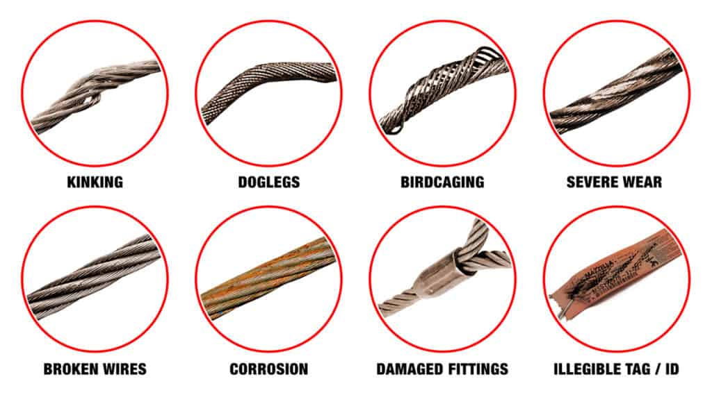
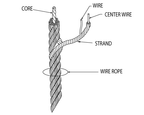
Significant distortion of the wire rope structure such as kinking, crushing, unstranding, birdcaging, signs of core failure or steel core protrusion between the outer strands.
In running wire ropes: Six randomly distributed broken wires in one rope lay or three broken wires in one strand in one rope lay, where a rope lay is the length along the rope in which one strand makes a complete revolution around the rope.
In rotation resistant ropes: Two randomly distributed broken wires in six rope diameters or four randomly distributed broken wires in 30 rope diameters.
In pendants or standing wire ropes: More than two broken wires in one rope lay located in rope beyond end connections and/or more than one broken wire in a rope lay located at an end connection.
If a deficiency in Category I (see paragraph (a)(2)(i) of this section) is identified, an immediate determination must be made by the competent person as to whether the deficiency constitutes a safety hazard. If the deficiency is determined to constitute a safety hazard, operations involving use of the wire rope in question must be prohibited until:
If the deficiency is localized, the problem is corrected by severing the wire rope in two; the undamaged portion may continue to be used. Joining lengths of wire rope by splicing is prohibited. If a rope is shortened under this paragraph, the employer must ensure that the drum will still have two wraps of wire when the load and/or boom is in its lowest position.
If a deficiency in Category II (see paragraph (a)(2)(ii) of this section) is identified, operations involving use of the wire rope in question must be prohibited until:
The employer complies with the wire rope manufacturer"s established criterion for removal from service or a different criterion that the wire rope manufacturer has approved in writing for that specific wire rope (see § 1926.1417),
If the deficiency is localized, the problem is corrected by severing the wire rope in two; the undamaged portion may continue to be used. Joining lengths of wire rope by splicing is prohibited. If a rope is shortened under this paragraph, the employer must ensure that the drum will still have two wraps of wire when the load and/or boom is in its lowest position.
If the deficiency (other than power line contact) is localized, the problem is corrected by severing the wire rope in two; the undamaged portion may continue to be used. Joining lengths of wire rope by splicing is prohibited. Repair of wire rope that contacted an energized power line is also prohibited. If a rope is shortened under this paragraph, the employer must ensure that the drum will still have two wraps of wire when the load and/or boom is in its lowest position.
Where a wire rope is required to be removed from service under this section, either the equipment (as a whole) or the hoist with that wire rope must be tagged-out, in accordance with § 1926.1417(f)(1), until the wire rope is repaired or replaced.
The inspection must include any deficiencies that the qualified person who conducts the annual inspection determines under paragraph (c)(3)(ii) of this section must be monitored.
Wire ropes on equipment must not be used until an inspection under this paragraph demonstrates that no corrective action under paragraph (a)(4) of this section is required.
At least every 12 months, wire ropes in use on equipment must be inspected by a qualified person in accordance with paragraph (a) of this section (shift inspection).
The inspection must be complete and thorough, covering the surface of the entire length of the wire ropes, with particular attention given to all of the following:
Exception: In the event an inspection under paragraph (c)(2) of this section is not feasible due to existing set-up and configuration of the equipment (such as where an assist crane is needed) or due to site conditions (such as a dense urban setting), such inspections must be conducted as soon as it becomes feasible, but no longer than an additional 6 months for running ropes and, for standing ropes, at the time of disassembly.
If the deficiency is localized, the problem is corrected by severing the wire rope in two; the undamaged portion may continue to be used. Joining lengths of wire rope by splicing is prohibited. If a rope is shortened under this paragraph, the employer must ensure that the drum will still have two wraps of wire when the load and/or boom is in its lowest position.
If the qualified person determines that, though not presently a safety hazard, the deficiency needs to be monitored, the employer must ensure that the deficiency is checked in the monthly inspections.
All documents produced under this section must be available, during the applicable document retention period, to all persons who conduct inspections under this section.

Scope. This section applies to slings used in conjunction with other material handling equipment for the movement of material by hoisting, in employments covered by this part. The types of slings covered are those made from alloy steel chain, wire rope, metal mesh, natural or synthetic fiber rope (conventional three strand construction), and synthetic web (nylon, polyester, and polypropylene).
Inspections. Each day before being used, the sling and all fastenings and attachments shall be inspected for damage or defects by a competent person designated by the employer. Additional inspections shall be performed during sling use, where service conditions warrant. Damaged or defective slings shall be immediately removed from service.
In addition to the inspection required by other paragraphs of this section, a thorough periodic inspection of alloy steel chain slings in use shall be made on a regular basis, to be determined on the basis of (A) frequency of sling use; (B) severity of service conditions; (C) nature of lifts being made; and (D) experience gained on the service life of slings used in similar circumstances. Such inspections shall in no event be at intervals greater than once every 12 months.
Employers must not use improved plow-steel wire rope and wire-rope slings with loads in excess of the rated capacities (i.e., working load limits) indicated on the sling by permanently affixed and legible identification markings prescribed by the manufacturer.
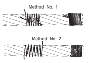
An eye splice made in any wire rope shall have not less than three full tucks. However, this requirement shall not operate to preclude the use of another form of splice or connection which can be shown to be as efficient and which is not otherwise prohibited.
Except for eye splices in the ends of wires and for endless rope slings, each wire rope used in hoisting or lowering, or in pulling loads, shall consist of one continuous piece without knot or splice.
Wire rope shall not be used if, in any length of eight diameters, the total number of visible broken wires exceeds 10 percent of the total number of wires, or if the rope shows other signs of excessive wear, corrosion, or defect.
Cable laid and 6 × 19 and 6 × 37 slings shall have a minimum clear length of wire rope 10 times the component rope diameter between splices, sleeves or end fittings.
Safe operating temperatures. Fiber core wire rope slings of all grades shall be permanently removed from service if they are exposed to temperatures in excess of 200 °F (93.33 °C). When nonfiber core wire rope slings of any grade are used at temperatures above 400 °F (204.44 °C) or below minus 60 °F (15.55 °C), recommendations of the sling manufacturer regarding use at that temperature shall be followed.
Wire rope slings shall have permanently affixed, legible identification markings stating size, rated capacity for the type(s) of hitch(es) used and the angle upon which it is based, and the number of legs if more than one.
Employers must not use natural- and synthetic-fiber rope slings with loads in excess of the rated capacities (i.e., working load limits) indicated on the sling by permanently affixed and legible identification markings prescribed by the manufacturer.
In manila rope, eye splices shall contain at least three full tucks, and short splices shall contain at least six full tucks (three on each side of the centerline of the splice).
In layed synthetic fiber rope, eye splices shall contain at least four full tucks, and short splices shall contain at least eight full tucks (four on each side of the centerline of the splice).
Strand end tails shall not be trimmed short (flush with the surface of the rope) immediately adjacent to the full tucks. This precaution applies to both eye and short splices and all types of fiber rope. For fiber ropes under 1-inch diameter, the tails shall project at least six rope diameters beyond the last full tuck. For fiber ropes 1-inch diameter and larger, the tails shall project at least 6 inches beyond the last full tuck. In applications where the projecting tails may be objectionable, the tails shall be tapered and spliced into the body of the rope using at least two additional tucks (which will require a tail length of approximately six rope diameters beyond the last full tuck).
Safe operating temperatures. Natural and synthetic fiber rope slings, except for wet frozen slings, may be used in a temperature range from minus 20 °F (-28.88 °C) to plus 180 °F (82.2 °C) without decreasing the working load limit. For operations outside this temperature range and for wet frozen slings, the sling manufacturer"s recommendations shall be followed.
Splicing. Spliced fiber rope slings shall not be used unless they have been spliced in accordance with the following minimum requirements and in accordance with any additional recommendations of the manufacturer:
In manila rope, eye splices shall consist of at least three full tucks, and short splices shall consist of at least six full tucks, three on each side of the splice center line.
In synthetic fiber rope, eye splices shall consist of at least four full tucks, and short splices shall consist of at least eight full tucks, four on each side of the center line.
Strand end tails shall not be trimmed flush with the surface of the rope immediately adjacent to the full tucks. This applies to all types of fiber rope and both eye and short splices. For fiber rope under 1 inch (2.54 cm) in diameter, the tail shall project at least six rope diameters beyond the last full tuck. For fiber rope 1 inch (2.54 cm) in diameter and larger, the tail shall project at least 6 inches (15.24 cm) beyond the last full tuck. Where a projecting tail interferes with the use of the sling, the tail shall be tapered and spliced into the body of the rope using at least two additional tucks (which will require a tail length of approximately six rope diameters beyond the last full tuck).
Removal from service. Natural and synthetic fiber rope slings shall be immediately removed from service if any of the following conditions are present:
Employers must use natural- and synthetic-fiber rope slings that have permanently affixed and legible identification markings that state the rated capacity for the type(s) of hitch(es) used and the angle upon which it is based, type of fiber material, and the number of legs if more than one.
Any wire rope in use should be inspected on a regular basis. You have too much at stake in lives and equipment to ignore thorough examination of the rope at prescribed intervals.
The purpose of inspection is to accurately estimate the service life and strength remaining in a rope so that maximum service can be had within the limits of safety. Results of the inspection should be recorded to provide a history of rope performance on a particular job.
On most jobs wire rope must be replaced before there is any risk of failure. A rope broken in service can destroy machinery and curtail production. It can also kill.
Because of the great responsibility involved in ensuring safe rigging on equipment, the person assigned to inspect should know wire rope and its operation thoroughly. Inspections should be made periodically and before each use, and the results recorded.
When inspecting the rope, the condition of the drum, sheaves, guards, cable clamps and other end fittings should be noted. The condition of these parts affects rope wear: any defects detected should be repaired.
To ensure rope soundness between inspections, all workers should participate. The operator can be most helpful by watching the ropes under his control. If any accident involving the ropes occurs, the operator should immediately shut down his equipment and report the accident to his supervisor. The equipment should be inspected before resuming operation.
The Occupational Safety and Health Act has made periodic inspection mandatory for most wire rope applications. If you need help locating the regulations that apply to your application, please give our rigging experts a call.
(a) Original crane/derrick wire rope and replacement wire rope must be selected and installed in accordance with the requirements of this section. Selection of replacement wire rope must be in accordance with the recommendations of the wire rope manufacturer, the crane/derrick manufacturer, or a qualified person.
(b) Wire rope design criteria: Wire rope (other than rotation resistant rope) must comply with either Option (1) or Option (2) of this section, as follows:
(ii) Option (2). Wire rope must be designed to have, in relation to the crane"s/derrick"s rated capacity, a sufficient minimum breaking force and design factor so that compliance with the applicable inspection provisions in this section will be an effective means of preventing sudden rope failure.
Type I rotation resistant wire rope (Type I). Type I rotation resistant rope is stranded rope constructed to have little or no tendency to rotate or, if guided, transmits little or no torque. It has at least 15 outer strands and comprises an assembly of at least 3 layers of strands laid helically over a center in two operations. The direction of lay of the outer strands is opposite to that of the underlying layer.
Type II rotation resistant wire rope (Type II). Type II rotation resistant rope is stranded rope constructed to have resistance to rotation. It has at least 10 outer strands and comprises an assembly of two or more layers of strands laid helically over a center in two or 3 operations. The direction of lay of the outer strands is opposite to that of the underlying layer.
Type III rotation resistant wire rope (Type III). Type III rotation resistant rope is stranded rope constructed to have limited resistance to rotation. It has no more than 9 outer strands, and comprises an assembly of two layers of strands laid helically over a center in two operations. The direction of lay of the outer strands is opposite to that of the underlying layer.
(C) Type I must have an operating design factor of no less than 5, except where the wire rope manufacturer and the crane/derrick manufacturer approves the design factor, in writing.
(iii) When Types II and III with an operation design factor of less than 5 are used (for nonduty cycle, nonrepetitive lifts), the following requirements must be met for each lifting operation:
(A) A qualified person must inspect the rope in accordance with subsection (2)(a) of this section. The rope must be used only if the qualified person determines that there are no deficiencies constituting a hazard. In making this determination, more than one broken wire in any one rope lay must be considered a hazard.
(C) Each lift made under these provisions must be recorded in the monthly and annual inspection documents. Such prior uses must be considered by the qualified person in determining whether to use the rope again.
(B) Rotation resistant ropes may be used as boom hoist reeving when load hoists are used as boom hoists for attachments such as luffing attachments or boom and mast attachment systems. Under these conditions, all of the following requirements must be met:
(III) The requirements of ANSI/ASME B30.5-2007, Section 5-1.3.2(a), (a)(2) through (a)(4), (b) and (d), except that the minimum pitch diameter for sheaves used in multiple rope reeving is 18 times the nominal diameter of the rope used instead of the value of 16 specified in Section 5-1.3.2(d).
(IV) All sheaves used in the boom hoist reeving system must have a rope pitch diameter of not less than 18 times the nominal diameter of the rope used.
(VI) The operating design factor for these ropes must be the total minimum breaking force of all parts of rope in the system divided by the load imposed on the rope system when supporting the static weights of the structure and the load within the crane"s/derrick"s rated capacity.
(f) Wire rope clips used in conjunction with wedge sockets must be attached to the unloaded dead end of the rope only, except that the use of devices specifically designed for dead-ending rope in a wedge socket is permitted.
(h) Prior to cutting a wire rope, seizings must be placed on each side of the point to be cut. The length and number of seizings must be in accordance with the wire rope manufacturer"s instructions.
(i) A competent person must begin a visual inspection prior to each shift the crane/derrick is used, which must be completed before or during that shift. The inspection must consist of observation of accessible wire ropes (running and standing) that are likely to be in use during the shift for apparent deficiencies, including those listed in (a)(ii) of this subsection. Untwisting (opening) of wire rope or booming down is not required as part of this inspection.
(I) Distortion of the wire rope structure such as kinking, crushing, unstranding, birdcaging, signs of core failure or steel core protrusion between the outer strands.
(I) Visibly broken wires in running wire ropes: 6 randomly distributed broken wires in one rope lay or 3 broken wires in one strand in one rope lay, where a rope lay is the length along the rope in which one strand makes a complete revolution around the rope;
(II) Visibly broken wires in rotation resistant ropes: Two randomly distributed broken wires in 6 rope diameters or 4 randomly distributed broken wires in 30 rope diameters;
(III) Visibly broken wires in pendants or standing wire ropes: More than two broken wires in one rope lay located in rope beyond end connections and/or more than one broken wire at an end connection; and
(A) If a deficiency in Category I is identified, an immediate determination must be made by the competent person as to whether the deficiency constitutes a safety hazard. If the deficiency is determined to constitute a safety hazard, operations involving use of the wire rope in question must be prohibited until:
(II) If the deficiency is localized, the problem is corrected by removing the damaged section of the wire rope; the undamaged portion may continue to be used. Joining lengths of wire rope by splicing is prohibited. If a rope is shortened under this subsection, you must ensure that the drum will still have two wraps of wire when the load and/or boom is in its lowest position.
(I) You comply with the wire rope manufacturer"s established criterion for removal from service or a different criterion that the wire rope manufacturer has approved in writing for that specific wire rope;
(C) If the deficiency is localized, the problem is corrected by severing the wire rope in two; the undamaged portion may continue to be used. Joining lengths of wire rope by splicing is prohibited. If a rope is shortened under this subsection, you must ensure that the drum will still have two wraps of wire when the load and/or boom is in its lowest position. If a deficiency in category III is identified, operations involving use of the wire rope in question must be prohibited until:
(II) If the deficiency (other than power line contact) is localized, the problem is corrected by severing the wire rope in two; the undamaged portion may continue to be used. Joining lengths of wire rope by splicing is prohibited. Repair of wire rope that contacted an energized power line is also prohibited. If a rope is shortened under this subsection, you must ensure that the drum will still have two wraps of wire when the load and/or boom is in its lowest position.
(D) Where a wire rope is required to be removed from service under this section, either the crane/derrick (as a whole) or the hoist with that wire rope must be tagged-out, in accordance with WAC 296-155-53400(67), until the wire rope is repaired or replaced.
(ii) The inspection must include any deficiencies that the qualified person who conducts the annual inspection determines under (c)(iii) of this subsection must be monitored.
(iii) Wire ropes on a crane/derrick must not be used until an inspection under this subsection demonstrates that no corrective action under (a)(iii) of this subsection is required.
(i) At least every 12 months, wire ropes in use on the crane/derrick must be inspected by a qualified person in accordance with (a) of this subsection (shift inspection).
(B) The inspection must be complete and thorough, covering the surface of the entire length of the wire ropes, with particular attention given to all of the following:
(C) Exception: In the event an inspection under (c)(ii) of this subsection is not feasible due to existing set-up and configuration of the crane/derrick (such as where an assist crane is needed) or due to site conditions (such as a dense urban setting). The inspection must consist of observation of the working range plus 3 additional wraps (running and standing) prior to use.
(II) If the deficiency is localized, the problem is corrected by severing the wire rope in two; the undamaged portion may continue to be used. Joining lengths of wire rope by splicing is prohibited. If a rope is shortened under this subsection, you must ensure that the drum will still have two wraps of wire when the load and/or boom is in its lowest position.
(B) If the qualified person determines that, though not presently a safety hazard, the deficiency needs to be monitored, you must ensure that the deficiency is checked in the monthly inspections.
(3) All documents produced under this section must be available, during the applicable document retention period, to all persons who conduct inspections under this section.

(3) Operational aids. Operations must not begin unless operational aids are in proper working order, except where the owner or lessee meets the specified temporary alternative measures. See WAC 296-155-53412 for the list of operational aids.Note:All accredited crane certifiers must meet and follow the requirements relating to fall protection, located in chapter 296-880 WAC, Unified safety standards for fall protection.
(a) Wire ropes must meet the crane or wire rope manufacturer"s specifications for size, type and inspection requirements. In the absence of the manufacturer"s specifications, follow the requirements for removal criteria located in this section, including Table 1.
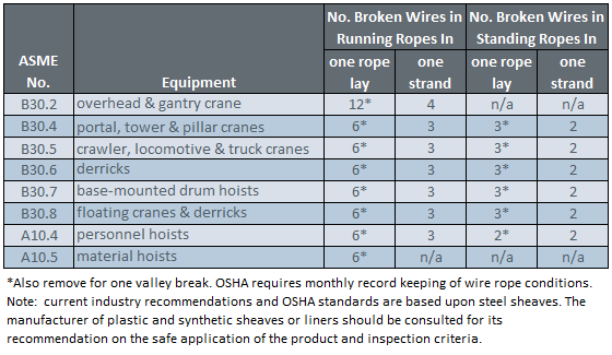
Derricks63Consult rope mfg.Consult rope mfg.32*Also remove if you detect 1 wire broken at the contact point with the core or adjacent strand; so called valley breaks or evidence from any heat damage from any cause.Note:xd means times the "diameter."
(b) The accredited crane certifier must perform a complete and thorough inspection covering the surface of the working range plus 3 additional wraps on the drum of the wire ropes.
(ii) If the deficiency is localized, the problem is corrected by severing the wire rope; the undamaged portion may continue to be used. Joining lengths of wire rope by splicing is prohibited.
(e) Replacement rope must be of a compatible size and have a strength rating at least as great as the original rope furnished or recommended by the crane manufacturer.
(a) Sheave grooves must be free from surface defects that could damage the rope. The cross-sectional radius at the bottom of the groove should be such as to form a close fitting saddle for the size of rope used. The sides of the groove must be tapered outward and rounded at the rim to facilitate entrance of the rope into the groove. Flange rims must run true about the axis of rotation.
(a) A safe test area must be selected and all traffic and unauthorized personnel and equipment must be cleared from test area. This test area must be roped off or otherwise secured to prevent entry of unauthorized personnel and equipment;

One topic that’s sure to spark a lively discussion among those who work in the lifting or material handling industries is, “Are import rigging products just as good as domestic products?” There’s a certain stigma attached to rigging products like hooks, wire rope, chain slings, and synthetic roundslings that are brought in to the U.S. from overseas.
25 or 30 years ago, if you asked an industry veteran if they trusted import products on the job site, the answer was clearly, “No.” Import products were viewed as inferior across the board—from shackles, sling hooks, wire rope, blocks, and wire rope clips. When import rigging products started hitting the market, there were horror stories of failed hooks, broken cables and slings, mislabeled and unmarked shackles—resulting in injuries to workers and expensive damage to equipment and materials.
Ultimately, the decision to choose a domestic or an imported wire rope, shackle, hook, sling or any other type of rigging product will come down to what best suits your company’s needs. There are obviously advantages and disadvantages to choosing either.
One thing to consider prior to purchasing an imported rigging product is to make sure that it meets federal specifications. For instance, if you’re considering using an imported wire rope, request a “certificate of conformance” from the distributor—this will at least give you documentation that the rope meets the RR-W-410 federal specifications required for domestic-made wire rope. It can also make certain that import rigging hardware items have the proper markings in accordance with federal standards.
Before you buy an imported rigging product, ask the question, “Have you tested the product?” Importers that vet foreign manufacturers should not rely solely on their supplier, and should always conduct their own set of in-house tests and inspection. Something as simple as providing documentation that a batch break test was performed stateside will tell you that the importer prioritizes safety and providing their customers with quality products. If they don’t test, don’t buy.
Wire ropes undergo constant stress and wear through daily use. So, wire rope requires monthly inspection in accordance with this section to reduce the risk of failure and potential resulting injury or property damage. In addition, this section covers criteria to use in determining when to replace rope, and requires inspection of rope on equipment that has been idle for a month or more, before the rope and equipment can be returned to service.
A thorough inspection of all ropes shall be made at least once a month and a certification record which included the date of inspection, the signature of the person who performed the inspection and an identifier for the ropes which were inspected shall be kept on file where readily available to appointed personnel. Any deterioration, resulting in appreciable loss of original strength, shall be carefully observed and determination made as to whether further use of the rope would constitute a safety hazard. Some of the conditions that could result in an appreciable loss of strength are the following:
All rope which has been idle for a period of a month or more due to shutdown or storage of a crane on which it is installed shall be given a thorough inspection before it is used. This inspection shall be for all types of deterioration and shall be performed by an appointed person whose approval shall be required for further use of the rope. A certification record shall be available for inspection which includes the date of inspection, the signature of the person who performed the inspection and an identifier for the rope which was inspected.
Wear and damage to wire rope can’t always be seen on the surface. Konecranes RopeQ Magnetic Rope Inspection pairs visual inspection with non-destructive testing to detect internal broken wires that may escape detection through traditional inspection methods.
Steel wire ropes have important applications in mine lifting, cable-stayed bridges, metallurgy, elevators, and so on. They are widely used due to their high strength, light weight, reliability, and efficiency [1]. Since wire ropes usually work in harsh environments, although they suffer from a variety of types of damage such as broken wire and wear, which affects the safety of production and even threatens the lives of workers [2]. To avoid accidents, manual inspection and regular replacement are generally used in engineering. However, manual inspection is time-consuming and laborious, and regular replacement usually causes great economic waste. According to a survey, more than 70% of replaced wire ropes still have initial breaking strength [3]. Therefore, it is of great importance to develop scientific and effective devices to inspect steel wire ropes.
There are two types of defects of steel wire ropes, loss of metallic cross-sectional area (LMA) and a localized fault (LF), and broken wire is the most typical outcome of LF. Among the various nondestructive testing techniques, magnetic flux leakage (MFL) method is most economical and effective for broken wire detection [4,5,6,7,8]. The basic principle of the MFL method is shown in Figure 1, where the permanent magnet magnetizes part of the wire rope to saturation, and a closed magnetic circuit is formed between the wire rope, the magnet and the yoke. When no damage is present, most of the magnetic induction lines pass through the inside of the wire rope. When there is a damage such as broken wire, the magnetic resistance of the damaged position increases, and part of the magnetic induction line leaks out to form the MFL. Magnetic sensitive elements are placed between the poles of the magnet to sense the MFL signal. The condition of the wire rope can be determined according to the received signal.
For decades, many experts and scholars have done a lot of research on the design of damage detecting sensors based on the MFL method [9,10,11,12,13]. Cao Y.N. et al. [9] proposed an approach for detecting LF of steel wire ropes using an annular array of Hall components. A back propagation (BP) network is used to classify the faults. This method can differentiate the degree and the width of local defects. Zhang J. et al. [10] applied the giant magneto-resistance (GMR) sensor to the detection of LF and LMA of the wire rope. Through the use of compressed sensing wavelet filtering and BP neural network, the accuracy and reliability of MFL sensor is improved. Wu B. [13] designed an MFL sensor based on tunnel magneto-resistive device. A blind hole with dimension of 0.3 mm in both depth and diameter is detectable for the sensor. The axial resolution to two adjacent notches with a width of 0.2 mm of the TMR-based MFL sensor can be less than 2.5 mm. However, arranging annular arrays of Hall components undoubtedly increases the complexity of the signal processing. Using magneto-resistive sensors can improve the sensitivity of the sensor, but it is difficult to be applied to actual inspections due to the micron-level requirements of the lift-off [13]. Therefore, designing a sensor that can be applied to the detection in actual engineering and is both simple and effective, has always been a problem for the condition monitoring of wire ropes.
The magnetic concentrating detection technology provides a new direction for the development of MFL sensors. The detection of wire ropes usually requires the arrangement of a plurality of magnetic sensitive elements. Especially for the large diameter wire ropes, it usually needs dozens of magnetic sensors, which greatly increases the difficulty of signal processing in the later stage. The magnetic concentrating principle can realize the leak-free detection of large diameter wire ropes through a small number of magnetic sensitive elements [14,15]. Kang et al. [14] theoretically analyzed the feasibility of magnetic concentrating detection. It is proved by calculation that the magnetic concentrator can collect the MFL and guide it into the Hall component through the bridge between the concentrators to realize the collection of weak leakage flux. At the same time, it can eliminate the strand-waveform noise of wire ropes and improve signal-to-noise ratio of the MFL signal. Wang et al. [15] analyzed the performance of the magnetic concentrators on collecting the MFL by finite element simulation and proposed the structure which is suitable for collecting the magnetic leakage flux. The structure was verified by experiments, which further promoted the development of the magnetic concentrating detection.
In this study, a sensor, which is constructed of ring-shaped magnets, a yoke, and a magnetic concentrator, is designed to detect broken wires of steel wire ropes. We optimized the structural parameters of the circumferential multi-circuit permanent magnet exciter (CMPME) and analyzed the performance of the magnetic concentrator on collecting MFL through the finite element method. Finally, the proposed sensor is applied in an experiment for broken wire detection. The induced MFL signal can be clearly recognized and the signal-to-noise ratio of the MFL signal is improved by discrete wavelet transform (DWT).
Wire ropes are structural components made of twisted wire that are widely employed in diverse areas. The safe usage of wire ropes is directly related to the production lifetime and personnel safety. Therefore, it is of great significance to develop an online detection and quantitative inspection system for wire ropes [1]. ElectroMagnetic Testing (EMT), the advantages of which include low cost, high reliability, and suitability for online detection of wire rope, has been widely used in wire rope application. EMTs include eddy current testing, magnetic particle testing, Magnetic Flux Leakage (MFL) detection, magnetic memory detection, microwave detection, and other methods. Among these, the MFL method can detect the surface and internal defects of wire rope, and has been greatly developed for its simple structure and portability [2].
In a traditional MFL detection, wire rope is magnetized to saturation, after which a magnetic probe is used to measure the MFL distribution. According to the form of the magnetic field source, there are two techniques: coil magnetization [3,4] and permanent magnet magnetization [5,6,7,8,9,10]. Singh [3] designed a magnetized device consisting of a variable-current saddle-shaped coil. This apparatus can be adjusted by controlling the magnitude of the current, but the device cannot be continuously used for the massive heating of the coil. Jomdecha et al. [4] improved a coil device of solenoid structure instead of traditional coil magnetizer. The magnetic field strength can be adjusted by changing the magnetizing current or magnetizing coil number. The multiple symmetrical yoke structures were composed of circumferentially distributed wire rope to magnetize its uniform saturation [5,6,7,8]. Wang et al. [9] considered the effects of different lift-off distances on detection accuracy during the magnetization process, and proposed an improved magnetization device. Xu et al. [11] used the finite element analysis method to optimize the structure of the excitation device, which was then validated by the experiment.
In a testing system, the magnetic field is converted into an electrical signal by a magnetic-to-electric convertor, such as an induction coil, a fluxgate, a Hall element, or a magnetoresistive sensor. Cao [12] proposed a detection device based on a Printed Circuit Board (PCB) split differential coil, obtaining a sum of MFL circumferential distribution signals. The device is useful for a certain span in the axial direction of the wire rope, but it is not sensitive to small width defects and circumferential defect information. Jomdecha et al. [4] improved the traditional induction coil by designing an induction coil array, with coils arranged on the circumferential wire rope. This system solved the problem of MFL circumferential information loss. Zhao et al. [13] designed a detection device in which 30 Hall sensors evenly surround the circumferential wire rope. This device can effectively obtain the information of the circumferential MFL distribution, but the Signal-to-Noise Ratio (SNR) of the collected signal is low. Peterka et al. [14] presented the results obtained by tracking the magnetic flux around the cable end and the signal runs from a particular design. Additionally, they investigated scanning elements placed above artificial defects created close to the cable end.
The signal that is collected by magnetic sensors contains ample background noise, so it is necessary to filter system noise. Cao et al. [12] proposed an algorithm for adaptive parameter spatial notch filtering to suppress strand wave, and the wavelet packet was used to filter out the high-frequency random noise. Zhang et al. [15,16] used the wavelet based on compressed sensing to denoise the strand wave and high-frequency noise, and then further proposed a channel-balance method based on the Hilbert-Huang transformation. Zhang et al. [17] used a spatial filter to reduce noise and smoothen the defect image. Zhang et al. [18] pretreated the MFL grayscale and effectively suppressed the noise interference. Tian et al. [19] combined the wavelet transform and the morphological transform to create a morphological filter algorithm that suppressed the interference associated with the baseline drift in the wire rope signal.
There are some problems among the existing MFL methods for defect detection in wire ropes:the excitation devices are cumbersome and inconvenient, the defect cannot be positioned in the circumferential direction, the wire rope is magnetized unevenly, and the SNR is low. A device to detect wire rope surface remanence strength was designed to solve these problems, and this solution is described in this paper. The wire rope was magnetized by permanent magnets, and the MFL information of the wire rope surface was collected after magnetization with giant magnetoresistive sensors, arranged evenly around the circumference of the wire rope. A wavelet filtering method based on Ensemble Empirical Mode Decomposition (EEMD) was used to denoise the original signal. The two-dimensional defect signal was processed and analyzed by digital image technology. To achieve quantitative classification, the defect image characteristics were extracted to express the MFL distribution information. The processing data were normalized to obtain the MFL grayscale image. The cubic spline interpolation was used to improve the circumferential resolution. The method of modulus maxima was used to locate and segment defects from the MFL image. The wavelet super-resolution reconstruction method was used to improve the resolution of the segmented image. Image descriptions of area, rectangle, elongation, and seven invariant moments were extracted as the feature vector of the defect, which was the input of a Back Propagation (BP) neural network, used to classify the defects.
Cloud Valley cableway in Huangshan is one of the most popular and busiest amusement cableway sites in China. Tens of Thousands of tourists and hikers visit the Huangshan Mountain Scenic Region and take transportation with this cableway system every day. The height difference is 775 meters between the two terminal stations. Single trip is about 2700m and the system is a single endless rope cableway with on-off rope clips. The steel wire rope is working as the major unit in the system to carry the cable cars and sustain the weights. Therefore, the integrity and competence of wire rope is the No.1 concern to the safety and reliability of the cableway system.
The role of TST is to help the cableway people identify and measure the severity of wire rope problems and provide solution for further maintenance and safety management of wire rope. And even better, we make the wire rope inspection and maintenance not only more reliable, but also more efficient and less costly.
According to the specific needs and operating scenario of Cloud Valley client, TST develops the realtime online wire rope inspection system which is able to:
3. Expected savings in wire rope inspection costs:32,000 USD/ Annum.(Compared to daily visual inspection procedure + 3rd party inspection service required)
For more information on the case of cableway wire rope inspection and general inquiries on TST wire rope inspection/maintenance solution, please contact: tst@tst-ly.com / emily@tst-ly.com

The article should be marked as indelibly and permanently as the nature of the product will permit. Marking that will not remain on the article during handling or for any other reason except deliberate removal is not a proper marking.
However, “E.C.” or “E.U.” for European Community or European Union, respectively, are not acceptable abbreviations since they do not indicate the individual country of origin of the good.


 8613371530291