
wire rope installation guide manufacturer
The majority of wire rope problems occurring during operation actually begin during installation, when the rope is at its greatest risk of being damaged. Proper installation procedures are vital in the protection and performance of wire rope products.
Until the rope is installed it should be stored on a rack, pallet or reel stand in a dry, well-ventilated storage shed or building. Tightly sealed and unheated structures should be avoided as condensation between rope strands may occur and cause corrosion problems. If site conditions demand outside storage, cover the rope with waterproof material and place the reel or coil on a support platform to keep it from coming directly in contact with the ground.
While lubrication is applied during the manufacturing process, the wire rope must still be protected by additional lubrication once it is installed. Lubricants will dry out over a period of time and corrosion from the elements will occur unless measures are taken to prevent this from happening. When the machine becomes idle for a period of time, apply a protective coating of lubricant to the wire rope. Moisture (dew, rain, and snow) trapped between strands and wires will create corrosion if the rope is unprotected. Also apply lubricant to each layer of wire rope on a drum because moisture trapped between layers will increase the likelihood of corrosion.
Always use the nominal diameter as specified by the equipment manufacturer. Using a smaller diameter rope will cause increased stresses on the rope and the probability of a critical failure is increased if the rated breaking strength does not match that of the specified diameter. Using a larger diameter rope leads to shorter service life as the rope is pinched in the sheave and drum grooves which were originally designed for a smaller diameter rope. Just as using a different diameter rope can create performance problems, so can the use of an excessively undersized or oversized rope.
Measure the wire rope using a parallel-jawed caliper as discussed in Measuring Rope Diameter at the top of this page. If the rope is the wrong size or outside the recommended tolerance, return the rope to the wire rope supplier. It is never recommended nor permitted by federal standards to operate cranes with the incorrect rope diameter. Doing so will affect the safety factor or reduce service life and damage the sheaves and drum. Note that in a grooved drum application, the pitch of the groove may be designed for the rope’s nominal diameter and not the actual diameter as permitted by federal standards.
Wire rope can be permanently damaged by improper unreeling or uncoiling practices. The majority of wire rope performance problems start here.Improper unreeling practices lead to premature rope replacement, hoisting problems and rope failure.
Place the payout reel as far away from the boom tip as is practical, moving away from the crane chassis. Never place the payout reel closer to the crane chassis than the boom point sheave. Doing so may introduce a reverse bend into the rope and cause spooling problems. Follow the guidelines highlighted under Unreeling and Uncoiling and Drum Winding. Take care to determine whether the wire rope will wind over or under the drum before proceeding. If the wire rope supplier secured the end of the rope to the reel by driving a nail through the strands, ask that in the future a U-bolt or other nondestructive tie-down method be used; nails used in this manner damage the rope.
Take extra precaution when installing lang lay, rotation-resistant, flattened strand or compacted ropes. Loss of twist must be avoided to prevent the strands from becoming loosened, causing looped wire problems.
The end of the rope must be securely and evenly attached to the drum anchorage point by the method recommended by the equipment manufacturer. Depending on the crane’s regulatory requirements, at least two to three wraps must remain on the drum as dead wraps when the rope is unwound during normal operations. Locate the dead end rope anchorage point on the drum in relation to the direction of the lay of the rope. Do not use an anchorage point that does not correspond with the rope lay. Mismatching rope lay and anchorage point will cause the wraps to spread apart from each other and allow the rope to cross over on the drum. Very gappy winding will occur resulting in crushing damage in multilayer applications.
Back tension must be continually applied to the payout reel and the crewman installing the rope must proceed at a slow and steady pace whether the drum is smooth or grooved.Regardless of the benefits of a grooved drum, tension must be applied to ensure proper spooling. An improperly installed rope on a grooved drum will wear just as quickly as an improperly installed rope on a smooth drum. If a wire rope is poorly wound and as a result jumps the grooves, it will be crushed and cut under operating load conditions where it crosses the grooves.
Every wrap on the first or foundation layer must be installed very tightly and be without gaps. Careless winding results in poor spooling and will eventually lead to short service life. The following layers of rope must lay in the grooves formed between adjacent turns of the preceding layer of rope. If any type of overwind or cross-winding occurs at this stage of installation and is not corrected immediately, poor spooling and crushing damage will occur.
On a multilayer spooling drum be sure that the last layer remains at least two rope diameters below the drum flange top. Do not use a longer length than is required because the excess wire rope will cause unnecessary crushing and may jump the flange. Loose wraps that occur at any time must be corrected immediately to prevent catastrophic rope failure.
The use of a mallet is acceptable to ensure tight wraps, however a steel-faced mallet should be covered with plastic or rubber to prevent damage to the rope wires and strands.
Rotation-resistant ropes of all constructions require extra care in handling to prevent rope damage during installation. The lay length of a rotation-resistant rope must not be disturbed during the various stages of installation. By introducing twist or torque into the rope, core slippage may occur—the outer strands become shorter in length, the core slips and protrudes from the rope. In this condition the outer strands become over- loaded because the core is no longer taking its designed share of the load. Conversely, when torque is removed from a rotation-resistant rope core slippage can also occur. The outer strands become longer and the inner layers or core become overloaded, reducing service life and causing rope failure.
The plain end of a wire rope must be properly secured. If the entire cross section of the rope is not firmly secured, core slippage may occur, causing the core to pull inside the rope’s end and allowing it to protrude elsewhere, either through the outer strands (popped core) or out the other end of the line. The outer layer of the outside strands may also become overloaded as there is no complete core-to-strand support.
Secure the ends of the rope with either seizing or welding methods as recommended under Seizing Wire Rope. It is imperative that the ends be held together tightly and uniformly throughout the entire installation procedure, including attaching the end through the wedge socket and the drum dead end wedge
When installing a new line, connect the old line to the new line by using a swivel-equipped cable snake or Chinese finger securely attached to the rope ends. The connection between the ropes during change-out must be very strong and prevent torque from the old rope being transferred into the new rope.Welding ropes together or using a cable snake without the benefit of a swivel increases the likelihood of introducing torque into the new rope. A swivel-equipped cable snake is not as easy as welding the ropes, but this procedure can be mastered with a little patience and practice.
Rope diameter is specified by the user and is generally given in the equipment manufacturer’s instruction manual accompanying the machine on which the rope is to be used.
Rope diameters are determined by measuring the circle that just touches the extreme outer limits of the strands— that is, the greatest dimension that can be measured with a pair of parallel-jawed calipers or machinist’s caliper square. A mistake could be made by measuring the smaller dimension.
The right way to unreel.To unreel wire rope from a heavy reel, place a shaft through the center and jack up the reel far enough to clear the floor and revolve easily. One person holds the end of the rope and walks a straight line away from the reel, taking the wire rope off the top of the reel. A second person regulates the speed of the turning reel by holding a wood block against the flange as a brake, taking care to keep slack from developing on the reel, as this can easily cause a kink in the rope. Lightweight reels can be properly unreeled using a vertical shaft; the same care should be taken to keep the rope taut.
The wrong way to unreel.If a reel of wire rope is laid on its flange with its axis vertical to the floor and the rope unreeled by throwing off the turns, spirals will occur and kinks are likely to form in the rope. Wire rope always should be handled in a way that neither twists nor unlays it. If handled in a careless manner, reverse bends and kinks can easily occur.
The right way to uncoil.There is only one correct way to uncoil wire rope. One person must hold the end of the rope while a second person rolls the coil along the floor, backing away. The rope is allowed to uncoil naturally with the lay, without spiraling or twisting. Always uncoil wire rope as shown.
The wrong way to uncoil.If a coil of wire rope is laid flat on the floor and uncoiled by pulling it straight off, spirals will occur and kinking is likely. Torsions are put into the rope by every loop that is pulled off, and the rope becomes twisted and unmanageable. Also, wire rope cannot be uncoiled like hemp rope. Pulling one end through the middle of the coil will only result in kinking.
Great stress has been placed on the care that should be taken to avoid kinks in wire rope. Kinks are places where the rope has been unintentionally bent to a permanent set. This happens where loops are pulled through by tension on the rope until the diameter of the loop is only a few inches. They also are caused by bending a rope around a sheave having too severe a radius. Wires in the strands at the kink are permanently damagedand will not give normal service, even after apparent “re-straightening.”
When wire rope is wound onto a sheave or drum, it should bend in the manner in which it was originally wound. This will avoid causing a reverse bend in the rope. Always wind wire rope from the top of the one reel onto the top of the other.Also acceptable, but less so, is re-reeling from the bottom of one reel to the bottom of another. Re-reeling also may be done with reels having their shafts vertical, but extreme care must be taken to ensure that the rope always remains taut. It should never be allowed to drop below the lower flange of the reel. A reel resting on the floor with its axis horizontal may also be rolled along the floor to unreel the rope.
Wire rope should be attached at the correct location on a flat or smooth-faced drum, so that the rope will spool evenly, with the turns lying snugly against each other in even layers. If wire rope is wound on a smooth-face drum in the wrong direction, the turns in the first layer of rope will tend to spread apart on the drum. This results in the second layer of rope wedging between the open coils, crushing and flattening the rope as successive layers are spooled.
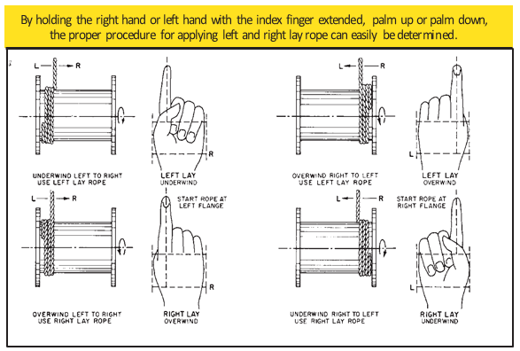
A simple method of determining how a wire rope should be started on a drum. The observer stands behind the drum, with the rope coming towards him. Using the right hand for right-lay wire rope, and the left hand for left lay wire rope, the clenched fist denotes the drum, the extended index finger the oncoming rope.
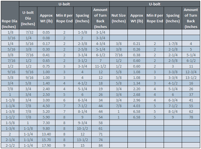
Clips are usually spaced about six wire rope diameters apart to give adequate holding power. They should be tightened before the rope is placed under tension. After the load is placed on the rope, tighten the clips again to take care of any lessening in rope diameter caused by tension of the load. A wire rope thimble should be used in the eye of the loop to prevent kinking.
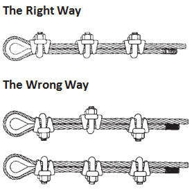
U-bolt Clips.There is only one correct method for attaching U-bolt clips to wire rope ends, as shown in TheRightWayimage below. The base of the clip bears on the live end of the rope; the “U” of the bolt bears on the dead end.
Compare this with the incorrect methods. Five of the six clips shown are incorrectly attached—only the center clip in the top view is correct. When the “U” of the clip bears on the live end of the rope, there is a possibility of the rope being cut or kinked, with subsequent failure.
Proper seizing and cutting operations are not difficult to perform, and they ensure that the wire rope will meet the user’s performance expectations. Proper seizings must be applied on both sides of the place where the cut is to be made. In a wire rope, carelessly or inadequately seized ends may become distorted and flattened, and the strands may loosen. Subsequently, when the rope is operated, there may be an uneven distribution of loads to the strands; a condition that will significantly shorten the life of the rope.
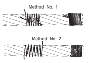
Either of the following seizing methods is acceptable. Method No. 1 is usually used on wire ropes over one inch in diameter. Method No. 2 applies to ropes one inch and under.
Method No. 1: Place one end of the seizing wire in the valley between two strands. Then turn its long end at right angles to the rope and closely and tightly wind the wire back over itself and the rope until the proper length of seizing has been applied. Twist the two ends of the wire together, and by alternately pulling and twisting, draw the seizing tight.
The Seizing Wire. The seizing wire should be soft or annealed wire or strand. Seizing wire diameter and the length of the seize will depend on the diameter of the wire rope. The length of the seizing should never be less than the diameter of the rope being seized.
Proper end seizing while cutting and installing, particularly on rotation-resistant ropes, is critical. Failure to adhere to simple precautionary measures may cause core slippage and loose strands, resulting in serious rope damage. Refer to the table below ("Suggested Seizing Wire Diameters") for established guidelines. If core protrusion occurs beyond the outer strands, or core retraction within the outer strands, cut the rope flush to allow for proper seizing of both the core and outer strands.
The majority of wire rope problems occurring during operation actually begin during installation, when the rope is at its greatest risk of being damaged. Proper installation procedures are vital in the protection and performance of wire rope products.
Until the rope is installed it should be stored on a rack, pallet or reel stand in a dry, well-ventilated storage shed or building. Tightly sealed and unheated structures should be avoided as condensation between rope strands may occur and cause corrosion problems. If site conditions demand outside storage, cover the rope with waterproof material and place the reel or coil on a support platform to keep it from coming directly in contact with the ground.
While lubrication is applied during the manufacturing process, the wire rope must still be protected by additional lubrication once it is installed. Lubricants will dry out over a period of time and corrosion from the elements will occur unless measures are taken to prevent this from happening. When the machine becomes idle for a period of time, apply a protective coating of lubricant to the wire rope. Moisture (dew, rain, and snow) trapped between strands and wires will create corrosion if the rope is unprotected. Also apply lubricant to each layer of wire rope on a drum because moisture trapped between layers will increase the likelihood of corrosion.
Always use the nominal diameter as specified by the equipment manufacturer. Using a smaller diameter rope will cause increased stresses on the rope and the probability of a critical failure is increased if the rated breaking strength does not match that of the specified diameter. Using a larger diameter rope leads to shorter service life as the rope is pinched in the sheave and drum grooves which were originally designed for a smaller diameter rope. Just as using a different diameter rope can create performance problems, so can the use of an excessively undersized or oversized rope.
Measure the wire rope using a parallel-jawed caliper as discussed in Measuring Rope Diameter at the top of this page. If the rope is the wrong size or outside the recommended tolerance, return the rope to the wire rope supplier. It is never recommended nor permitted by federal standards to operate cranes with the incorrect rope diameter. Doing so will affect the safety factor or reduce service life and damage the sheaves and drum. Note that in a grooved drum application, the pitch of the groove may be designed for the rope’s nominal diameter and not the actual diameter as permitted by federal standards.
Wire rope can be permanently damaged by improper unreeling or uncoiling practices. The majority of wire rope performance problems start here.Improper unreeling practices lead to premature rope replacement, hoisting problems and rope failure.
Place the payout reel as far away from the boom tip as is practical, moving away from the crane chassis. Never place the payout reel closer to the crane chassis than the boom point sheave. Doing so may introduce a reverse bend into the rope and cause spooling problems. Follow the guidelines highlighted under Unreeling and Uncoiling and Drum Winding. Take care to determine whether the wire rope will wind over or under the drum before proceeding. If the wire rope supplier secured the end of the rope to the reel by driving a nail through the strands, ask that in the future a U-bolt or other nondestructive tie-down method be used; nails used in this manner damage the rope.
Take extra precaution when installing lang lay, rotation-resistant, flattened strand or compacted ropes. Loss of twist must be avoided to prevent the strands from becoming loosened, causing looped wire problems.
The end of the rope must be securely and evenly attached to the drum anchorage point by the method recommended by the equipment manufacturer. Depending on the crane’s regulatory requirements, at least two to three wraps must remain on the drum as dead wraps when the rope is unwound during normal operations. Locate the dead end rope anchorage point on the drum in relation to the direction of the lay of the rope. Do not use an anchorage point that does not correspond with the rope lay. Mismatching rope lay and anchorage point will cause the wraps to spread apart from each other and allow the rope to cross over on the drum. Very gappy winding will occur resulting in crushing damage in multilayer applications.
Back tension must be continually applied to the payout reel and the crewman installing the rope must proceed at a slow and steady pace whether the drum is smooth or grooved.Regardless of the benefits of a grooved drum, tension must be applied to ensure proper spooling. An improperly installed rope on a grooved drum will wear just as quickly as an improperly installed rope on a smooth drum. If a wire rope is poorly wound and as a result jumps the grooves, it will be crushed and cut under operating load conditions where it crosses the grooves.
Every wrap on the first or foundation layer must be installed very tightly and be without gaps. Careless winding results in poor spooling and will eventually lead to short service life. The following layers of rope must lay in the grooves formed between adjacent turns of the preceding layer of rope. If any type of overwind or cross-winding occurs at this stage of installation and is not corrected immediately, poor spooling and crushing damage will occur.
On a multilayer spooling drum be sure that the last layer remains at least two rope diameters below the drum flange top. Do not use a longer length than is required because the excess wire rope will cause unnecessary crushing and may jump the flange. Loose wraps that occur at any time must be corrected immediately to prevent catastrophic rope failure.
The use of a mallet is acceptable to ensure tight wraps, however a steel-faced mallet should be covered with plastic or rubber to prevent damage to the rope wires and strands.
Rotation-resistant ropes of all constructions require extra care in handling to prevent rope damage during installation. The lay length of a rotation-resistant rope must not be disturbed during the various stages of installation. By introducing twist or torque into the rope, core slippage may occur—the outer strands become shorter in length, the core slips and protrudes from the rope. In this condition the outer strands become over- loaded because the core is no longer taking its designed share of the load. Conversely, when torque is removed from a rotation-resistant rope core slippage can also occur. The outer strands become longer and the inner layers or core become overloaded, reducing service life and causing rope failure.
The plain end of a wire rope must be properly secured. If the entire cross section of the rope is not firmly secured, core slippage may occur, causing the core to pull inside the rope’s end and allowing it to protrude elsewhere, either through the outer strands (popped core) or out the other end of the line. The outer layer of the outside strands may also become overloaded as there is no complete core-to-strand support.
Secure the ends of the rope with either seizing or welding methods as recommended under Seizing Wire Rope. It is imperative that the ends be held together tightly and uniformly throughout the entire installation procedure, including attaching the end through the wedge socket and the drum dead end wedge
When installing a new line, connect the old line to the new line by using a swivel-equipped cable snake or Chinese finger securely attached to the rope ends. The connection between the ropes during change-out must be very strong and prevent torque from the old rope being transferred into the new rope.Welding ropes together or using a cable snake without the benefit of a swivel increases the likelihood of introducing torque into the new rope. A swivel-equipped cable snake is not as easy as welding the ropes, but this procedure can be mastered with a little patience and practice.

Industrial wire ropes are designed for extreme resilience and strength. They can withstand thousands of pounds of pressure and be used on all types of applications. However, issues with the wire rope installation process can significantly decrease its longevity and even its capacity and durability.
When wire ropes are not used properly, it can create an unsafe environment. The rope can snap, even if the load it’s supporting is below its maximum load limit. In anoted by the IMCA (International Marine Contractors Association), a wire rope sling rope broke due to improper installation. A crew member was seriously injured after the sling disconnected and hit the worker.
Many of these common accidents are easily avoidable through correct wire rope installation. Here are five of the most common mistakes made and how to prevent them on your worksite.
Determining the diameter of the wire rope is an essential step of the installation process. Installers are required to double-check that the correct diameter rope is being used, as this impacts the rope’s breaking strength and load limit.
Wire ropes are measured with a parallel-jawed caliper (also called a machinist’s caliper). This is placed over the wire rope to measure the diameter – but if the rope is inserted at the wrong angle, you will get an inaccurate result.
The strands of a wire rope must be flush against the measuring portion of the caliper. If a raised strand is at the top, the measurement will have a smaller dimension, which could affect breaking strength calculations.
Wire ropes are reeled onto these spools for easy handling and shipments, as it prevents the rope from getting tangled or crushed. But unreeling the wire rope incorrectly can cause severe damage, such as snagged wires, twists, kinks, or unraveled strands.
A common mistake that is often made is to unreel the wire rope by laying the spool vertically on its axis. The wire rope has to be yanked off of the spool, which increases the likelihood of it getting kinked or twisted. The wire rope should also not touch the ground as it is unreeled, as this could damage the wires as well.
Instead, the reeled wire rope should be placed on a shaft that allows the spool to turn 360°. It also should require two people, one to slowly pull the rope off of the spool in a straight line and another to regulate the speed by controlling the turn rate.
Occasionally ais added during wire rope installation to create a load-bearing eye or to connect two cables together. These small but mighty pieces only diminish a wire rope’s strength by around 10%, if they are added correctly.
These little issues can cause the wire rope to slip out of the clip. It is very important to follow the directions and use the right number of clips with the correct spacing in-between, depending on the rope’s diameter and approximate load weight.
Sometimes a damaged wire rope can be repaired through a method called seizing. First, the rope is cut at a straight angle, then a wire is tightly wound around this end to prevent the strands from unraveling.
Two methods can be used to securely seize a wire rope. First, it can be placed at a right angle between the starting and ending point of the seizing. The wire is then wrapped around this angled piece to hold it in place, and the ends are twisted together to secure it. Another option is to wrap the seizing wire around and twist the two end pieces together, creating a tourniquet type of attachment.
The type of end preparations recommended depends on several factors. This includes the diameter of the rope and the number of wires and strands. In some cases, double seizing and fuse welding is required for additional securement. Failing to follow these instructions could result in the core or strands of the wire rope to slip and unravel.
Although wire ropes are usually damaged due to improper use, they can get ruined during storage as well. Failing to follow through with routine maintenance and storage recommendations could cause the wire rope to rust, unravel, or kink. Further, keeping your wire rope on the ground, in wet areas, or directly in hot sunlight can cause it to break down faster.
the right way can improve their long-term performance and use. This includes following all instructions during wire rope installation, as well as storage and upkeep. Wire ropes should be cleaned before going into storage and may need lubricant from time to time to protect the wires from drying out.
Wire ropes are intended to be a strong, reliable piece of industrial hardware. There is no reason to compromise its durability due to simple installation mistakes. By avoiding these common mishaps, you can ensure a far safer work environment and also extend the use of your wire ropes.
Another tip is to start by purchasing top-quality hardware from a trusted wire rope supplier. Elite Sales is proud to carry a vast selection of wire rope sizes, styles, and finishes that are made to fit many applications.
Original equipment wire rope and replacement wire rope must be selected and installed in accordance with the requirements of this section. Selection of replacement wire rope must be in accordance with the recommendations of the wire rope manufacturer, the equipment manufacturer, or a qualified person.
Wire rope design criteria: Wire rope (other than rotation resistant rope) must comply with either Option (1) or Option (2) of this section, as follows:
Option (1). Wire rope must comply with section 5-1.7.1 of ASME B30.5-2004 (incorporated by reference, see § 1926.6) except that section"s paragraph (c) must not apply.
Option (2). Wire rope must be designed to have, in relation to the equipment"s rated capacity, a sufficient minimum breaking force and design factor so that compliance with the applicable inspection provisions in § 1926.1413 will be an effective means of preventing sudden rope failure.
Type I rotation resistant wire rope ("Type I"). Type I rotation resistant rope is stranded rope constructed to have little or no tendency to rotate or, if guided, transmits little or no torque. It has at least 15 outer strands and comprises an assembly of at least three layers of strands laid helically over a center in two operations. The direction of lay of the outer strands is opposite to that of the underlying layer.
Type II rotation resistant wire rope ("Type II"). Type II rotation resistant rope is stranded rope constructed to have significant resistance to rotation. It has at least 10 outer strands and comprises an assembly of two or more layers of strands laid helically over a center in two or three operations. The direction of lay of the outer strands is opposite to that of the underlying layer.
Type III rotation resistant wire rope ("Type III"). Type III rotation resistant rope is stranded rope constructed to have limited resistance to rotation. It has no more than nine outer strands, and comprises an assembly of two layers of strands laid helically over a center in two operations. The direction of lay of the outer strands is opposite to that of the underlying layer.
Type I must have an operating design factor of no less than 5, except where the wire rope manufacturer and the equipment manufacturer approves the design factor, in writing.
A qualified person must inspect the rope in accordance with § 1926.1413(a). The rope must be used only if the qualified person determines that there are no deficiencies constituting a hazard. In making this determination, more than one broken wire in any one rope lay must be considered a hazard.
Each lift made under § 1926.1414(e)(3) must be recorded in the monthly and annual inspection documents. Such prior uses must be considered by the qualified person in determining whether to use the rope again.
Rotation resistant ropes may be used as boom hoist reeving when load hoists are used as boom hoists for attachments such as luffing attachments or boom and mast attachment systems. Under these conditions, all of the following requirements must be met:
The requirements in ASME B30.5-2004 sections 5-1.3.2(a), (a)(2) through (a)(4), (b) and (d) (incorporated by reference, see § 1926.6) except that the minimum pitch diameter for sheaves used in multiple rope reeving is 18 times the nominal diameter of the rope used (instead of the value of 16 specified in section 5-1.3.2(d)).
The operating design factor for these ropes must be the total minimum breaking force of all parts of rope in the system divided by the load imposed on the rope system when supporting the static weights of the structure and the load within the equipment"s rated capacity.
Wire rope clips used in conjunction with wedge sockets must be attached to the unloaded dead end of the rope only, except that the use of devices specifically designed for dead-ending rope in a wedge socket is permitted.
Prior to cutting a wire rope, seizings must be placed on each side of the point to be cut. The length and number of seizings must be in accordance with the wire rope manufacturer"s instructions.

The coil of rope should be placed on the ground and rolled out straight, ensuring that it does not become contaminated with dust, grit, moisture or other harmful material.
The rope should never be pulled away from a stationary coil as this will induce turn into the rope and form kinks. If the coil is too large to physically handle it may need to be placed on a turntable which will allow the rope to be paid out as the end of the rope is pulled away from the coil.
A shaft of adequate strength should be passed through the reel bore and the reel places in a suitable stand which allows it to rotate and be braked to avoid overrun during installation.
Where multi-layer coiling is involved the rope should be placed in equipment that has the capability of providing a back tension in the rope as it is being transferred from the supply reel to the drum. This is to ensure that the underlying laps of rope, particularly in the bottom layer, are wound tightly on the drum.
The supply reel should be positioned such that the fleet angle during installation is kept to a minimum. If a loop forms in the rope it should not be allowed to tighten to form a kink.
The reel stand should be mounted so as not to create a reverse bend during reeving, i.e. for a drum with an upper wind rope, take the rope off the top of the supply reel
Otherwise, winding can be performed by hanging the wire drum up in a crane hook, the hook must be lowered max., A sufficient weight (2.5% -5% of the wire MBL) must be hooked, and the steel wire could be wound close to the drum

Wire rope is shipped in cut lengths, either in coils or on reels. Great care should be taken when the rope is removed from the shipping package since it can be permanently damaged by improper unreeling or uncoiling. Looping the rope over the head of the reel or pulling the rope off a coil while it is lying on the ground, will create loops in the line. Pulling on a loop will, at the very least, produce an imbalance in the rope and may result in open or closed kinks (Fig. 18). Once a rope is kinked, the damage is not repairable. The kink must be cut out or the rope is unfit for service.
Figure 18.Improper handling can create open (a) or, closed kinks b). The open kink will open the rope lay: the closed kink will close it. Starting loop (c): Do not allow the rope to form a loop. If. however, a loop does form and is removed at the stage show. a kink can be avoided. Kink (d): In this case. the looped rope was put under tension, the kink was formed. the rope is permanently damaged.
There are three methods to perform this step correctly:The reel is mounted on a shaft supported by two jacks or a roller payoff (Fig.19). Since the reel is free to rotate, the rope is pulled from the reel by a workman holding the rope end, and walking away from the reel as it unwinds. A braking device should be employed so that the rope is kept taut and the reel is restrained from over-running the rope. This is necessary particularly with powered de-reeling equipment.
Another method involves mounting the reel on an unreeling stand (Fig. 20). It is then unwound in the same manner as described above (1). In this case, however, greater care must be exercised to keep the rope under tension sufficient to prevent the accumulation of slack. Slack can allow the rope to drop below the lower reel head and be damaged or loose wraps on the reel to fall
In another accepted method, the end of the rope is held while the reel itself is rolled along the ground. With this procedure, the rope will payoff properly however, the end being held will travel in the direction the reel is being rolled. As the difference between the diameter of the reel head and the diameter of the wound rope increases, the speed of travel will increase.
Figure 19. The wire rope reel is mounted on a shaft supported by jacks. This permits the reel to rotate freely. and the rope can be unwound either manually or by a powered mechanism.
When re-reeling wire rope from a horizontally supported reel to a drum it is preferable for the rope to travel from the top of the reel to the top of the drum; or, from the bottom of the reel to the bottom of the drum (Fig. 21). Re-reeling in this manner will avoid putting a reverse bend into the rope during installation. If a rope is installed so that a reverse bend is induced, it may cause the rope to become "twisty" and, consequently, harder to handle. When unwinding wire rope from a coil, there are two suggested methods for carrying out this procedure in a proper manner:
1) One method involves placing the coil on a vertical unreeling stand. The stand consists of a base with a fixed vertical shaft. On this shaft there is a "swift," consisting of a plate with inclined pins positioned so that the coil may be placed over them. The whole swift and coil then rotate as the rope is pulled off. This method is particularly effective when the rope is to be wound on a drum.
2) The most common as well as the easiest uncoiling method is merely to hold one end of the rope while rolling the coil along the ground like a hoop (Fig. 22). Figures 23 and 24 show unreeling and uncoiling methods that are most likely to cause kinks. Such improper procedures must be avoided in order to prevent the occurrence of loops. These loops, when pulled taut, will inevitably result in kinks. No matter how a kink develops, it will damage strands and wires, and the kinked section must be cut out. Proper and careful handling will keep the wire rope free from kinks.
Drums are the means y which power is transmitted to the rope and then to the object to be moved. For the wire rope to pick up this power efficiently and to transmit it properly to the working end, the installation must be carefully controlled. If the drum is grooved, the winding conditions should be closely supervised to assure adherence to the following recommended procedures:
I) The end of the rope must be secured to the drum by such means as will give the end termination at least as much strength as is specified by the equipment manufacturer.
2) Adequate tension must be maintained on the rope while it is being wound so that the winding proceeds under continuous tension. Back tension applied to the rope during installation" should be from 2 to 5% of the minimum breaking force of the rope being installed.
4) It is preferable to have at least three dead wraps remaining on the drum when the rope is unwound during normal operation. Two dead wraps are a mandatory requirement in many codes and standards. If the wire rope is carelessly wound and, as a result, jumps the grooves, it will be crushed and cut where it crosses from one groove to the other. Another, almost unavoidable problem is created at the drum flange; as the rope climbs to a second layer there is further crushing and the wires receive excessive abrasion.
drum grooves relative to the actual rope diameter. Wire rope is normally manufactured to a plus tolerance. (See Table 3.) The oversize tolerance of the rope must be taken into account or the rope will be damaged by poor spooling caused
inches. Yet, by Federal standards, a 1/4-inch rope may have a diameter as large as .265 inches. If a rope of this size were to be operated on a drum with a .250 inch pitch, crowding would occur and the rope would be forced out of the groove.
Installation of a wire rope on a plain (smooth) face drum requires a great deal of care. The starting position should be at the correct drum flange so that each wrap of the rope will wind tightly against the preceding wrap (Fig. 32). Here too, close supervision should be maintained during installation. This will help make certain that:
2 ) Appropriate tension on the rope is maintained as it is wound on the drum. Back tension applied to the rope during installation should be from 2 to 5% of the minimum breaking force of the rope being installed.
4) It is preferable to have at least three dead wraps remaining on the drum when the rope is unwound during normal operation. Two dead wraps are a mandatory requirement in many codes and standards. Loose and uneven winding on a plain (smooth) faced drum can and usually does create excessive wear, crushing and distortion of the rope. The results of such abuse are shorter service life and a reduction in the rope"s effective strength. Also, for an operation that is sensitive in terms of moving and spotting a load, the operator will encounter control difficulties as the rope will pile up, pull into the pile and fall from the pile to the drum surface. The ensuing shock can break or otherwise damage the rope.
Figure 32. By holding the right or left hand with index finger extended, palm up or palm down, the proper procedure for applying left-and right-lay rope on a smooth drum can be easily determined.
The proper direction of winding the first layer on a smooth drum can be determined by standing behind the drum and looking along the path the rope travels, and then following one of the procedures illustrated in Figure 32. The diagrams show: the correct relationship that should be maintained between the direction of lay of the rope (right or left), the direction of rotation of the drum (overwind or underwind) and winding from left to right or right to left. Order Wire Rope & Cable
Many installations are designed with requirements for winding more than one layer of wire rope on a drum. Winding multiple layers presents some further problems.The first layer should wind in a smooth, tight helix which, if the drum is grooved,
is already established. The grooves allow the operator to work off the face of the drum, and permit the minimum number of dead wraps. A smooth drum present" an additional problem, initially, as the wire rope must be wound in such a manner that the first layer will be smooth and uniform and will provide a firm foundation for the layers of rope that will be wound over it. The first layer of rope on the smooth drum should be wound with tension (2 to 5% of the minimum breaking force of the rope) sufficient to assure a close helix - each wrap being wound as close as possible to the preceding wrap. The first layer then acts as a groove which will guide the successive layers. Unlike wire ropes operating on grooved drums, the first layer should not be unwound from a smooth-faced drum with multiple layers. After the rope has wound completely across the face of the drum (either smooth or grooved), it is forced up to a second layer at the flange. The rope then winds back across the drum in the opposite direction, lying in the valleys between the wraps of the rope on the first layer. Advancing across the drum on the second layer, the rope, following the "grooves" formed by the rope on the first layer, actually winds back one wrap in each revolution of the drum. The rope must then cross one or two rope "grooves" (depending upon the type of grooving - single or double cross-over) in order to advance across the drum for each turn. The point at which this occurs is known as the cross-over. Cross-over is unavoidable on the second, and all succeeding layers. Figure 33 illustrates the winding of a rope on the second layer from left to right, and from right to left-the direction is shown by the arrows.
At these cross-over points, the rope is subjected to severe abrasion and crushing as it is pushed over the "grooves" and rides across the crown of the first rope layer. The scrubbing of the rope, as this is happening, can easily be heard.
Helical grooving does not employ a built in cross-over and does not work as well for multiple layers spooling as a counterbalanced drum because it does not have the cross-over and does not consistently put the rope in the proper position at the
Counterbalance grooving with two cross-overs is made so that each wrap of rope winds parallel to the drum flange for a distance less than half the circumference around the drum, then follows a short cross-over to complete half the drum circumference. The cross-over is at an angle with the drum flange and displaces the rope laterally by half the pitch of grooving.
The grooving for this type of winding is similar to the parallel grooving except that half the drum circumference is laterally displaced from the other half by half the pitch of grooving, and between these two halves the grooves make short cross-overs to guide the rope properly. The two cross-over areas are on opposite sides of the drum, or 1800 apart.
Since the lateral displacement of each cross-over is one half the pitch of grooving, or one half the displacement of the cross-overs encountered with other types of winding, "throw" of the rope is reduced, decreasing the whipping action. However, if the interval between these displacements happens to match the rope"s vibration cycle, whipping can still become severe because this action is cumulative.
With counterbalance winding, the change of layers can be controlled better than with other systems and is preferred when a rope must wind in many layers on the drum.
Buying new crane ropes is a detailed and thorough process. While it may be time-consuming, wire rope replacement prioritizes safety for your workers, minimizes downtime on a jobsite, maximizes the lifespan of the crane and avoids the costly and time-consuming process of getting correct rope onsite and respooling your crane.
Sometimes, it can seem like the wire rope buying process is overly complicated. This is done on purpose to avoid as many issues as possible when the new rope is installed. The reason for that is so buyers avoid putting the wrong types of ropes on cranes and unnecessarily increasing the risk of injuries to workers or damage to loads being lifted. The processes are to make sure to prevent that added risk and put the correct rope on the correct machine, per Original Equipment Manufacturer (OEM) specifications.
Wire rope specialists ask these questions to understand your circumstances and what your needs are. With this information, they are better prepared to get the absolute correct rope.
Most of the time, the customer should have access to their crane’s operations manual that will show what rope diameter and length is specified. The customer may have to measure or come up with his own calculations on length. The crane manufacturer is going to make a specific drum for that specific type of wire rope.
The rope has to be specific to the lagging of the drum for that machine, which is why there are multiple variations for each size of wire rope because each kind is specific to the type of crane, and it shouldn’t be substituted. Mazzella will only install the rope that is the correct brand and tolerance on a particular crane.
Ordering the correct crane rope will prevent crane rope damage. The wrong rope could cause damage to the equipment, and at worst, boom failure. On the less severe side, you will have bad performance or it might not work at all. You could have twist and/or spooling issues. That could lead to the crane failing altogether, which creates downtime as you wait for the correct wire rope to be ordered/delivered and installed.
Many crane owners are working for somebody else when they’re doing jobs, so if the rope doesn’t work, they’re paying for work that is not getting done and falling behind schedule.
On the more severe side, you could total your crane and/or irreparably damage the load being lifted if you use the wrong wire rope. In the worst-case scenario, using the incorrect rope could result in severe injury and/or the loss of life.
Sometimes, customers assume that there’s a one-size-fits-all replacement, that if it’s a non-rotating rope, it should work on every application. There’s a lot of misinformation on what will work and what won’t work. With our experience and access to all brands of wire rope, Mazzella guarantees we can get you the right rope for your cranes. If Mazzella isn’t comfortable with the project, we won’t supply the wire rope.
If the wrong wire rope is ordered and delivered, it could be hours or days before the correct rope is on location. Especially with a lot of the larger cranes, manufacturers are shipping model-specific ropes all over the country, and depending on location and money, that could cause delays on your jobsite.
With our large inventory of rope, Mazzella can have a new spool of wire on a truck and out for delivery in a matter of hours. Avoid the pitfalls of ordering the wrong crane rope and you’ll have a new spool of wire rope on its way. Once the order process is done, what can your company do to prepare for delivery and installation?
As much as Mazzella can be prepared on our end, the customer needs to be ready for installation so the process can go as smoothly and safely as possible.
It is a good idea to give management the proper notice of when the installer will be on-site, have the necessary technicians on-site to help the installer with the rope replacement and make sure the installer/technicians have a clear working space.
Also, Mazzella recommends you measure your sheaves with a sheave gauge. A sheave gauge will help you measure the wear of the root, the amount of wear on the groove wall and the diameter of the wire rope.
After ordering the correct rope and having the requisite space and approval for installation, how long will it take to remove and replace the old rope when the technician, assistants and supplies arrive onsite? For some small cranes, the timeframe could be as little as 45 minutes, but for larger cranes, removing the old rope and installing the new one could be a several-hour process.
There’s a lot of factors that go into a successful crane rope installation. The most important thing is the quicker your supplier responds to your order and gets a rope on location, the quicker that rope gets installed properly, saving time and money. Downtime is the key, and it could cost companies tens of thousands of dollars per day if their crane(s) are inoperable.
Once a new crane rope is installed, a break-in period or tension period is recommended to make sure everything is performing correctly, and help you avoid shock-loading the newly installed wire rope. The break-in period is recommended because installation and spooling equipment are not going to put adequate tension on the rope. A break-in period consists of putting a low percentage of the working load limit weight on the rope for several lift cycles, and running the blocks up to the boom length (working height) and back down. For the most specific guidelines on the breaking-in process for your new wire rope, refer to the manufacturer’s recommendations.
If a brand-new wire rope on a crane is not broken in properly before lifting a large load, it potentially could damage the rope and render useless the equipment that was just installed on your machine.
When Mazzella fulfills a crane ropes order, it is not just about the sale and the bottom line. While we’re in the business of selling crane ropes, we’re also in the business of building relationships and trust. We are committed to making sure you get the correct products for the right applications.
Crane rope issues don’t just happen 9-to-5 during the normal work week. They happen Friday nights, holidays, weekends and early mornings. They’re always on the clock, and it is just about being honest with the customer and letting them know, they type of rope that is required. That honesty and trust is of utmost importance for the safety of your workers and the proper maintenance of your cranes.
Mazzella has one of the largest crane ropes inventories in the United States. The company provides wire rope assemblies and manufactures bridge cables, crane cables, steel mill cables and thousands of OEM assemblies in sizes from ¼ to 3-inch diameter and 9 to 52 millimeter diameter, domestic and non-domestic and in stock and ready for same or next-day shipment.


 8613371530291