
wire rope lanyards free sample
Wire Rope Lanyards are made from durable aircraft cable and are typically attached to pins and other fasteners to prevent loss. They may be used as tethers for components and also used as door restraint cables.
We specialize in custom wire rope lanyards to suit your specific application. Virtually endless configurations are available- limited only by your imagination! View examples of some of the common end fittings used . Don’t see what you need? Just ask! We can help to create the perfect lanyard assembly for your application.
Typical wire rope coatings include PVC and Nylon. PVC coating is more popular because of its appearance, flexibility, and low cost. Nylon offers more durability and abrasion resistance. Coatings are available in many colors.

(1) Lifelines, lanyards and deceleration devices should be attached to an anchorage and connected to the body-belt or body harness in the same manner as they would be when used to protect employees.
(4) For rope-grab-type deceleration systems, the length of the lifeline above the centerline of the grabbing mechanism to the lifeline"s anchorage point should not exceed 2 feet (0.61 m).
(5) For lanyard systems, for systems with deceleration devices which do not automatically limit free fall distance to 2 feet (0.61 m ) or less, and for systems with deceleration devices which have a connection distance in excess of 1 foot (0.3 m) (measured between the centerline of the lifeline and the attachment point to the body belt or harness), the test weight should be rigged to free fall a distance of 7.5 feet (2.3 m) from a point that is 1.5 feet (.46 m) above the anchorage point, to its hanging location (6 feet below the anchorage). The test weight should fall without interference, obstruction, or hitting the floor or ground during the test. In some cases a non-elastic wire lanyard of sufficient length may need to be added to the system (for test purposes) to create the necessary free fall distance.
(6) For deceleration device systems with integral lifelines or lanyards which automatically limit free fall distance to 2 feet (0.61 m) or less, the test weight should be rigged to free fall a distance of 4 feet (1.22 m).
(B) For deceleration device systems with integral lifelines or lanyards which automatically limit free fall distance to 2 feet (0.61 m) or less, the test weight should free fall a distance equal to that permitted by the system in normal use. (For example, to test a system with a self-retracting lifeline or lanyard, the test weight should be supported and the system allowed to retract the lifeline or lanyard as it would in normal use. The test weight would then be released and the force and deceleration distance measured).
(2) "Rope-grab-type deceleration devices." (i) Devices should be moved on a lifeline 1,000 times over the same length of line a distance of not less than 1 foot (30.5 cm), and the mechanism should lock each time.
(a) "Selection and use considerations." (1) The kind of personal fall arrest system selected should match the particular work situation, and any possible free fall distance should be kept to a minimum. Consideration should be given to the particular work environment. For example, the presence of acids, dirt, moisture, oil, grease, etc., and their effect on the system, should be evaluated. Hot or cold environments may also have an adverse effect on the system. Wire rope should not be used where an electrical hazard is anticipated. As required by the standard, the employer must plan to have means available to promptly rescue an employee should a fall occur, since the suspended employee may not be able to reach a work level independently.
(2) Where lanyards, connectors, and lifelines are subject to damage by work operations such as welding, chemical cleaning, and sandblasting, the component should be protected, or other securing systems should be used. The employer should fully evaluate the work conditions and environment (including seasonal weather changes) before selecting the appropriate personal fall protection system. Once in use, the system"s effectiveness should be monitored. In some cases, a program for cleaning and maintenance of the system may be necessary.
(c) "Component compatibility considerations." Ideally, a personal fall arrest system is designed, tested, and supplied as a complete system. However, it is common practice for lanyards, connectors, lifelines, deceleration devices, body belts and body harnesses to be interchanged since some components wear out before others. The employer and employee should realize that not all components are interchangeable. For instance, a lanyard should not be connected between a body belt (or harness) and a deceleration device of the self-retracting type since this can result in additional free fall for which the system was not designed. Any substitution or change to a personal fall arrest system should be fully evaluated or tested by a competent person to determine that it meets the standard, before the modified system is put in use.
(d) "Employee training considerations." Thorough employee training in the selection and use of personal fall arrest systems is imperative. Employees must be trained in the safe use of the system. This should include the following: application limits; proper anchoring and tie-off techniques; estimation of free fall distance, including determination of deceleration distance, and total fall distance to prevent striking a lower level; methods of use; and inspection and storage of the system. Careless or improper use of the equipment can result in serious injury or death. Employers and employees should become familiar with the material in this Appendix, as well as manufacturer"s recommendations, before a system is used. Of uppermost importance is the reduction in strength caused by certain tie-offs (such as using knots, tying around sharp edges, etc.) and maximum permitted free fall distance. Also, to be stressed are the importance of inspections prior to use, the limitations of the equipment, and unique conditions at the worksite which may be important in determining the type of system to use.
(e) "Instruction considerations." Employers should obtain comprehensive instructions from the supplier as to the system"s proper use and application, including, where applicable:
(6) Proper hook-up, anchoring and tie-off techniques, including the proper dee-ring or other attachment point to use on the body belt and harness for fall arrest;
(g) "Inspection considerations." As required by 1926.502(d)(21), personal fall arrest systems must be regularly inspected. Any component with any significant defect, such as cuts, tears, abrasions, mold, or undue stretching; alterations or additions which might affect its efficiency; damage due to deterioration; contact with fire, acids, or other corrosives; distorted hooks or faulty hook springs; tongues unfitted to the shoulder of buckles; loose or damaged mountings; non-functioning parts; or wearing or internal deterioration in the ropes must be withdrawn from service immediately, and should be tagged or marked as unusable, or destroyed.
(h) "Tie-off considerations." (1) One of the most important aspects of personal fall protection systems is fully planning the system before it is put into use. Probably the most overlooked component is planning for suitable anchorage points. Such planning should ideally be done before the structure or building is constructed so that anchorage points can be incorporated during construction for use later for window cleaning or other building maintenance. If properly planned, these anchorage points may be used during construction, as well as afterwards.
(i) Properly planned anchorages should be used if they are available. In some cases, anchorages must be installed immediately prior to use. In such cases, a registered professional engineer with experience in designing fall protection systems, or another qualified person with appropriate education and experience should design an anchor point to be installed.
(ii) In other cases, the Agency recognizes that there will be a need to devise an anchor point from existing structures. Examples of what might be appropriate anchor points are steel members or I-beams if an acceptable strap is available for the connection (do not use a lanyard with a snaphook clipped onto itself); large eye-bolts made of an appropriate grade steel; guardrails or railings if they have been designed for use as an anchor point; or masonry or wood members only if the attachment point is substantial and precautions have been taken to assure that bolts or other connectors will not pull through. A qualified person should be used to evaluate the suitable of these "make shift" anchorages with a focus on proper strength.
(2) Employers and employees should at all times be aware that the strength of a personal fall arrest system is based on its being attached to an anchoring system which does not reduce the strength of the system (such as a properly dimensioned eye-bolt/snap-hook anchorage). Therefore, if a means of attachment is used that will reduce the strength of the system, that component should be replaced by a stronger one, but one that will also maintain the appropriate maximum arrest force characteristics.
(3) Tie-off using a knot in a rope lanyard or lifeline (at any location) can reduce the lifeline or lanyard strength by 50 percent or more. Therefore, a stronger lanyard or lifeline should be used to compensate for the weakening effect of the knot, or the lanyard length should be reduced (or the tie-off location raised) to minimize free fall distance, or the lanyard or lifeline should be replaced by one which has an appropriately incorporated connector to eliminate the need for a knot.
(4) Tie-off of a rope lanyard or lifeline around an "H" or "I" beam or similar support can reduce its strength as much as 70 percent due to the cutting action of the beam edges. Therefore, use should be made of a webbing lanyard or wire core lifeline around the beam; or the lanyard or lifeline should be protected from the edge; or free fall distance should be greatly minimized.
(5) Tie-off where the line passes over or around rough or sharp surfaces reduces strength drastically. Such a tie-off should be avoided or an alternative tie-off rigging should be used. Such alternatives may include use of a snap-hook/dee ring connection, wire rope tie-off, an effective padding of the surfaces, or an abrasion-resistance strap around or over the problem surface.
(7) The strength of an eye-bolt is rated along the axis of the bolt and its strength is greatly reduced if the force is applied at an angle to this axis (in the direction of shear). Also, care should be exercised in selecting the proper diameter of the eye to avoid accidental disengagement of snap-hooks not designed to be compatible for the connection.
(i) "Vertical lifeline considerations." As required by the standard, each employee must have a separate lifeline [except employees engaged in constructing elevator shafts who are permitted to have two employees on one lifeline] when the lifeline is vertical. The reason for this is that in multiple tie-offs to a single lifeline, if one employee falls, the movement of the lifeline during the arrest of the fall may pull other employees" lanyards, causing them to fall as well.
(j) "Snap-hook considerations." (1) Although not required by this standard for all connections until January 1, 1998, locking snaphooks designed for connection to suitable objects (of sufficient strength) are highly recommended in lieu of the nonlocking type. Locking snaphooks incorporate a positive locking mechanism in addition to the spring loaded keeper, which will not allow the keeper to open under moderate pressure without someone first releasing the mechanism. Such a feature, properly designed, effectively prevents roll-out from occurring.
(2) As required by 1926.502(d)(6), the following connections must be avoided (unless properly designed locking snaphooks are used) because they are conditions which can result in roll-out when a nonlocking snaphook is used:
(vi) Improper dimensions of the dee-ring, rebar, or other connection point in relation to the snaphook dimensions which would allow the snaphook keeper to be depressed by a turning motion of the snaphook.
(l) "Elongation and deceleration distance considerations." Other factors involved in a proper tie-off are elongation and deceleration distance. During the arresting of a fall, a lanyard will experience a length of stretching or elongation, whereas activation of a deceleration device will result in a certain stopping distance. These distances should be available with the lanyard or device"s instructions and must be added to the free fall distance to arrive at the total fall distance before an employee is fully stopped. The additional stopping distance may be very significant if the lanyard or deceleration device is attached near or at the end of a long lifeline, which may itself add considerable distance due to its own elongation. As required by the standard, sufficient distance to allow for all of these factors must also be maintained between the employee and obstructions below, to prevent an injury due to impact before the system fully arrests the fall. In addition, a minimum of 12 feet (3.7 m) of lifeline should be allowed below the securing point of a rope grab type deceleration device, and the end terminated to prevent the device from sliding off the lifeline. Alternatively, the lifeline should extend to the ground or the next working level below. These measures are suggested to prevent the worker from inadvertently moving past the end of the lifeline and having the rope grab become disengaged from the lifeline.
(n) "Other considerations." Because of the design of some personal fall arrest systems, additional considerations may be required for proper tie-off. For example, heavy deceleration devices of the self-retracting type should be secured overhead in order to avoid the weight of the device having to be supported by the employee. Also, if self-retracting equipment is connected to a horizontal lifeline, the sag in the lifeline should be minimized to prevent the device from sliding down the lifeline to a position which creates a swing hazard during fall arrest. In all cases, manufacturer"s instructions should be followed.
(3) Lanyards and vertical safety lines which tie-off one employee shall have a minimum breaking strength of 5,000 pounds. All ends shall be spliced or swaged as per the manufacturer"s specifications. Knots shall not be permitted at ends or anywhere along the length of the lanyard or "safety line".
(4) Self-retracting safety lines and lanyards which automatically limit free fall distance to two feet or less shall have components capable of sustaining a minimum static tensile load of 3,000 pounds applied to the device with the safety line or lanyard in the fully extended position.
(5) Self-retracting safety lines and lanyards which do not limit free fall distance to two feet or less, ripstitch lanyards, and tearing and deforming lanyards shall be capable of sustaining a minimum tensile load of 5,000 pounds applied to the device with the safety line or lanyard in the fully extended position.
(11) Ropes and straps (webbing) used in lanyards, safety lines, and strength components of body harnesses, shall be made from synthetic fibers or wire rope.
(12) All body harnesses and lanyards manufactured on or before January 1, 1998, shall be designed and built to conform to ANSI A10.14-1975, Requirements for Safety Belts, Harnesses, Lanyards, Lifelines and Drop Lines for Construction and Industrial Use, which is hereby incorporated by reference.
(B) When used by employees having a combined tool and body weight of 310 pounds or more, personal fall arrest systems which meet the criteria and protocols contained in paragraphs (b), (c) and (d) in Section II may be considered as complying with the provisions of subparagraphs (d)(l)(A) through (d)(1)(C), provided that the criteria and protocols are modified appropriately to provide proper protection for such heavier weights.
(1) Safety lines, lanyards and deceleration devices shall be attached to an anchorage and connected to the body harness in the same manner as they would be when used to protect employees.
(4) For rope-grab-type deceleration systems, the length of the safety line above the centerline of the grabbing mechanism to the safety line"s anchorage point shall not exceed two feet.
(5) For lanyard systems, for systems with deceleration devices which do not automatically limit free fall distance to two feet or less, and for systems with deceleration devices which have a connection distance in excess of one foot (measured between the centerline of the safety line and the attachment point to the body belt or harness) the test weight shall be rigged to free fall a distance of 7.5 feet from a point that is 1.5 feet above the anchorage point, to its hanging location (six feet below the anchorage). The test weight shall fall without interference, obstruction, or hitting the floor or ground during the test. In some cases, a non-elastic wire lanyard of sufficient length may need to be added to the system (for test purposes) to create the necessary free fall distance.
(6) For deceleration device systems with integral safety lines or lanyards which automatically limit free fall distance to two feet or less, the test weight shall be rigged to free fall a distance of four feet.
2. For deceleration device systems with integral safety lines or lanyards which automatically limit free fall distance to two feet or less, the test weight shall free fall a distance equal to that permitted by the system in normal use. (For example, to test a system with a self-retracting safety line or lanyard, the test weight shall be supported and the system allowed to retract the safety line or lanyard as it would in normal use. The test weight would then be released and the force and deceleration distance measured).
(a) Selection and Use Considerations. The kind of personal fall arrest system selected should match the particular work situation, and any possible free fall distance should be kept to a minimum. Consideration should be given to the particular work environment. For example, the presence of acids, dirt, moisture, oil, grease, etc., and their effect on the system should be evaluated. Hot or cold environments may also have an adverse affect on the system. Wire rope should not be used where an electrical hazard is anticipated. As required by the standard, the employer must plan to have means available to promptly rescue an employee should a fall occur, since the suspended employee may not be able to reach a work level independently.
Where lanyards, connectors, and safety lines are subject to damage by work operations such as welding, chemical cleaning, and sandblasting, the component should be protected or other securing systems should be used. The employer should fully evaluate the work conditions and environment (including seasonal weather changes) before selecting the appropriate personal fall protection system. Once in use, the system"s effectiveness should be monitored. In some cases, a program for cleaning and maintenance of the system may be necessary.
(c) Component Compatibility Considerations. Ideally, a personal fall arrest system is designed, tested, and supplied as a complete system. However, it is common practice for lanyards, connectors, safety lines, deceleration devices, and body harnesses to be interchanged since some components wear out before others. The employer and employee should realize that not all components are interchangeable. For instance, a lanyard should not be connected between a body harness and a deceleration device of the self-retracting type since this can result in additional free fall for which the system was not designed. Any substitution or change to a personal fall arrest system should be fully evaluated or tested by a qualified person to determine that it meets the standard, before the modified system is put in use.
Thorough employee training in the selection and use of personal fall arrest systems is imperative. As stated in the standard, before the equipment is used, employees must be trained in the safe use of the system. This should include the following: Application limits; proper anchoring and tie-off techniques; estimation of free fall distance, including determination of deceleration distance, and total fall distance to prevent striking a lower level; methods of use; and inspection and storage of the system. Careless or improper use of the equipment can result in serious injury or death. Employers and employees should become familiar with the material in this appendix, as well as manufacturer"s recommendations, before a system is used. Of uppermost importance is the reduction in strength caused by certain tie-offs (such as using knots, tying around sharp edges, etc.) and maximum permitted free fall distance. Also, to be stressed are the importance of inspections prior to use, the limitations of the equipment, and unique conditions at the worksite which may be important in determining the type of system to use.
(e) Instruction Considerations. Employers should obtain comprehensive instructions from the supplier as to the system"s proper use and application, including, where applicable:
(6) Proper hook-up, anchoring and tie-off techniques, including the proper dee-ring or other attachment point to use on the body harness for fall arrest;
(f) Inspection Considerations. As stated in the standard (Section I, paragraph (f)), personal fall arrest systems must be regularly inspected. Any component with any significant defect, such as cuts, tears, abrasions, mold, or undue stretching; alterations or additions which might affect its efficiency; damage due to deterioration; contact with fire, acids, or other corrosives; distorted hooks or faulty hook springs; tongues unfitted to the shoulder of buckles; loose or damaged mountings; non-functioning parts; or wearing or internal deterioration in the ropes must be withdrawn from service immediately, and should be tagged or marked as unusable, or destroyed.
(1) One of the most important aspects of personal fall protection systems is fully planning the system before it is put into use. Probably the most overlooked component is planning for suitable anchorage points. Such planning should ideally be done before the structure or building is constructed so that anchorage points can be incorporated during construction for use later for window cleaning or other building maintenance. If properly planned, these anchorage points may be used during construction, as well as afterwards.
(2) Employers and employees should at all times be aware that the strength of a personal fall arrest system is based on its being attached to an anchoring system which does not significantly reduce the strength of the system (such as properly dimensioned eye- bolt/snap-hook anchorage). Therefore, if a means of attachment is used that will reduce the strength of the system, that component should be replaced by a stronger one, but one that will also maintain the appropriate maximum arrest force characteristics.
(3) Tie-off using a knot in a rope lanyard or safety line (at any location) can reduce the safety line or lanyard strength by 50 percent or more. Therefore, a stronger lanyard or safety line should be used to compensate for the weakening effect of the knot, or the lanyard length should be reduced (or the tie-off location raised) to minimize free fall distance, or the lanyard or safety line should be replaced by one which has an appropriately incorporated connector to eliminate the need for a knot.
(4) Tie-off a rope lanyard or safety line around an "H" or "I" beam or similar support can reduce its strength as much as 70 percent due to the cutting action of the beam edges. Therefore, use should be made of a webbing lanyard or wire core safety lines around the beam; or the lanyard or safety line should be protected from the edge; or free fall distance should be greatly minimized.
(5) Tie-off where the line passes over or around rough or sharp surfaces reduces strength drastically. Such a tie-off should be avoided or an alternative tie-off rigging should be used. Such alternatives may include use of a snaphook/dee ring connection, wire rope tie-off, an effective padding of the surfaces, or an abrasion-resistance strap around or over the problem surface.
(7) The strength of an eve-bolt is rated along the axis of the bolt and its strength is greatly reduced if the force is applied at an angle to this axis (in the direction of shear). Also, care should be exercised in selecting the proper diameter of the eye to avoid accidental disengagement of snap-hooks not designed to be compatible for the connection.
(i) Vertical Safety Line Considerations. As required by the standard, each employee must have a separate safety line when the safety line is vertical. The reason for this is that in multiple tie-offs to a single safety line, if one employee falls, the movement of the safety line during the arrest of the fall may pull other employees" lanyards, causing them to fall as well.
(k) Elongation and Deceleration Distance Considerations. Other factors involved in a proper tie-off are elongation and deceleration distance. During the arresting of a fall, a lanyard will experience a length of stretching or elongation, whereas activation of a deceleration device will result in a certain stopping distance. These distances should be available with the lanyard or device"s instructions and must be added to the free fall distance to arrive at the total fall distance before an employee is fully stopped. The additional stopping distance may be very significant if the lanyard or deceleration device is attached near or at the end of a long safety line, which may itself add considerable distance due to its own elongation. As required by the standard, sufficient distance to allow for all of these factors must also be maintained between the employee and obstructions below, to prevent an injury due to impact before the system fully arrests the fall. In addition, a minimum of 12 feet of safety line should be allowed below the securing point of a rope grab type deceleration device, and the end terminated to prevent the device from sliding off the safety line should extend to the ground or the next working level below. These measures are suggested to prevent the worker from inadvertently moving past the end of the safety line and having the rope grab become disengaged from the safety line.
(m) Other Considerations. Because of the design of some personal fall arrest systems, additional considerations may be required for proper tie-off. For example, heavy deceleration devices of the self-retracting type should be secured overhead in order to avoid the weight of the device having to be supported by the employee. Also, if self-retracting equipment is connected to a horizontal safety line, the sag in the safety line should be minimized to prevent the device from sliding down the safety line to a position which creates a swing hazard during fall arrest. In all cases, manufacturer"s instructions should be followed.

A system composed of a synthetic or wire rope installed horizontally between two anchors, to which a worker attaches a personal fall protection system.
A synthetic or wire rope, rigged from one or more anchors, to which a worker’s lanyard or other part of a personal fall protection system is attached.
A deceleration device which travels on a lifeline and automatically, by friction, engages the lifeline and locks so as to arrest the fall of an employee. A rope grab usually employs the principle of inertial locking, cam/level locking or both (also referred to as a fall arrester).
TheFrench Creek Dual Leg Six Foot Wire Rope Shock Absorbing Lanyard with Snap Hooksgives you 100% tie-off with minimal tripping hazards. Constructed of vinyl-coated wire cable. The wire cable creates a durable and secure connection in almost any circumstance. The inline shock absorbing pack helps reduce fall forces. With locking snaps you know you"ll be secure in your tie-off.
Stainless Steel Cable LanyardsSteel lanyard solutions are used to securely and flexibly link and connect physical objects in a range of industries. Corrosion-resistant stainless steel cable lanyards are especially useful in environments where the moisture level is high, including steel aircraft cable assemblies, marine cable applications and medical devices.
At Motion Control Technologies, you can find the type, length and quantity of stainless steel cable lanyards to meet your needs. We ship orders within one business day, so you can get your lanyards fast. Browse our online store for steel lanyard solutions today.
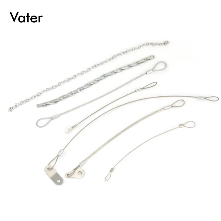
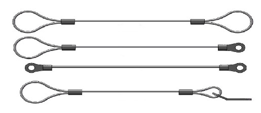
We have different stainless steel cable lanyards to meet different types of securing challenges. Our bulk stainless steel lanyards range in length from 6’ to 24’ and include:
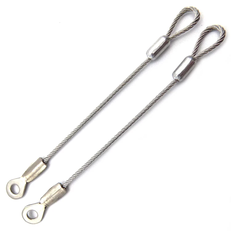
Eye/Eye Stainless Steel Cable Lanyards: A stainless steel 3/64 7×7 SS cable coated to 1/16th clear nylon, with a stainless steel eye on each end so you can secure the rope. The bare cable version would be a 3/64 7×7 SS cable. We are also providing these lanyards with a 1/16 7×7 bare or coated to 3/32 and a 1/8 7×19 bare or coated to 3/16
Just like the eye/eye stainless steel cable lanyards, but with a 1” stainless steel loop instead of eyes on each end. The loop/ loop lanyard is available in 3 sizes. A 3/64 7×7 bare or coated to 1/16, a 1/16 7×7 bare or coated to 3/32, and a 1/8 7×19 bare or coated to 3/16.
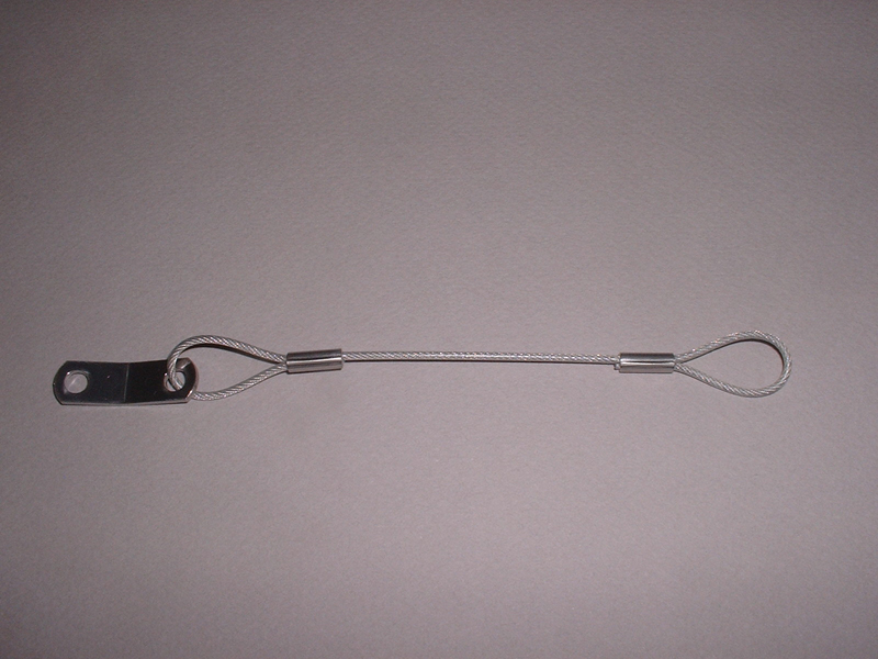
Loop/Eye Stainless Steel Cable Lanyards: The same strong, corrosion-resistant cable with the 1” loop on one end and the eye on the other. The loop/ eye lanyard is available in 3 sizes. A 3/64 7×7 bare or coated to 1/16, a 1/16 7×7 bare or coated to 3/32, and a 1/8 7×19 bare or coated to 3/16.
Loop/Loop/Tab Stainless Steel Cable Lanyards: Identical to the loop/loop stainless steel cable lanyard, but with the added benefit of a stainless steel mounting tab attached to one of the loops. The loop/ loop/ tab lanyard is available in 2 sizes. A 3/64 7×7 bare or coated to 1/16 and a 1/16 7×7 bare or coated to 3/32.
At Motion Control Technologies, we offer customized stainless steel cable assemblies. With our large inventory of cables and fittings, we work with you to arrange stainless steel cable assemblies that are specific to your business needs. Engineering stainless cable lanyards requires considering many factors, including the type of load and the construction and diameter of the cable itself.
For example, if you’re in the automotive industry, we offer everything from push-pull technology to custom mechanical brake cables and automotive mechanical cable lanyards. If your company manufactures sporting goods, we can help with bicycle brake and shift cables, fishing equipment and more.

Like any other wire rope, lanyards are created by, first, twisting strands of metal wires into a helix. This bundle of twisted wires can then be twisted together with other similar bundles in the same fashion as before to form the wire rope lanyard.
Depending on the strength requirements of the intended application, different numbers of each set of strands can be used. For example, a common wire rope lanyard construction consists of a bundle of nineteen small wires being twisted together with seven other similar bundles. This is called a 7x19 construction, with the first number representing the number of bundles and the second number representing the number of wires in each bundle. Other common construction types include 1x19, 7x7, 6x19, 6x25, 8x19, and 8x25.
To really customize your wire rope lanyard, you can also select from a wide range of end fittings and terminals. These can drastically alter how the cable can be used. Thimbles, handles, stops, strap eyes, threaded studs, and ball terminals are just a few of the many fitting options at your disposal.


 8613371530291