
wire rope lifting capacity chart factory
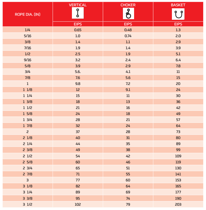
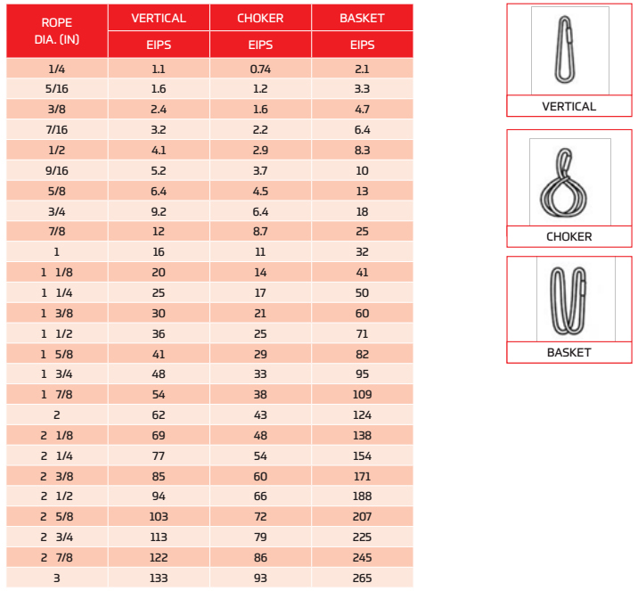
VERTICAL, or straight, attachment is simply using a sling to connect a lifting hook to a load. Full rated lifting capacity of the sling may be utilized, but must not be exceeded. A tagline should be used to prevent load rotation, which may damage a sling.
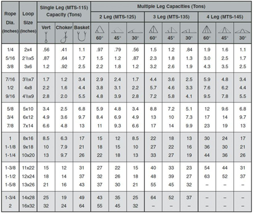
When two or more slings are attached to the same lifting hook, the total hitch becomes, in effect, a lifting bridle, and the load is distributed equally among the individual slings.
CHOKERhitches reduce lifting capability of a sling since this method of rigging affects ability of the wire rope components to adjust during the lift. A choker is used when the load will not be seriously damaged by the sling body — or the sling damaged by the load, and when the lift requires the sling to snug up against the load.
The diameter of the bend where the sling contacts the load should keep the point of choke against the sling BODY — never against a splice or the base of the eye. When a choke is used at an angle of less than 120 degrees (see next page), the sling-rated capacity must be adjusted downward.
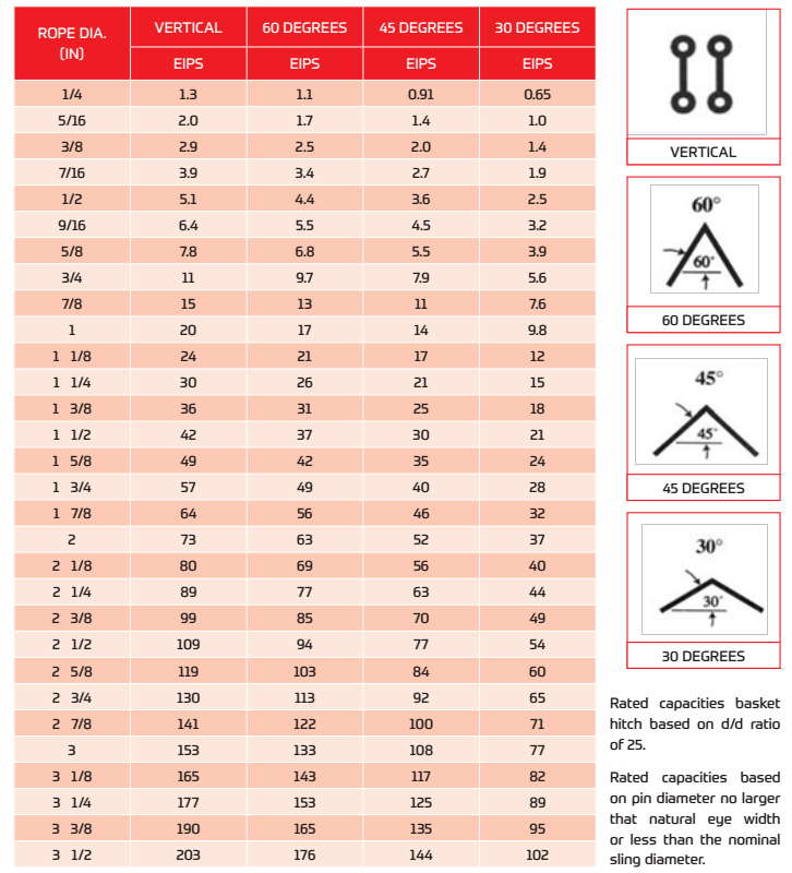
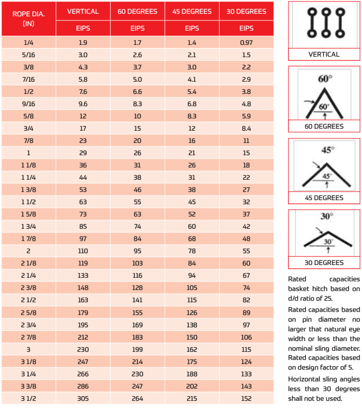
Anytime pull is exerted at an angle on a leg—or legs—of a sling, the load per leg can be determined by using the data in the table above. Proceed as follows to calculate this load—and determine the rated capacity required of the sling, or slings, needed for a lift.First, divide the total load to be lifted by the number of legs to be used. This provides the load per leg if the lift were being made with all legs being vertically.
Then MULTIPLY the load per leg (as computed above) by the Load Factor for the leg angle being used (from the table at the bottom) – to compute the ACTUAL LOAD on each leg for this lift and angle. THE ACTUAL LOAD MUST NOT EXCEED THE RATED SLING CAPACITY.
The horizontal angle of bridles with 3 or more legs is measured the same as the horizontal sling angle of 2-legged hitches. In this case, where a bridle designed with different leg lengths results in horizontal angles, the leg with the smallest horizontal angle will carry the greatest load. Therefore, the smallest horizontal angle is used in calculating actual leg load and evaluating the rated capacity of the sling proposed.
On the other hand, the eye should always be used on a hook or pin with at least the nominal diameter of the rope—since applying the D/d Ratio shows an efficiency loss of approximately 50% when the relationship is less than 1/1.
When rigged as a basket, DIAMETER of the bend where a sling contacts the load can be a limiting factor on sling capacity. Standard D/d ratios— where “D” is the diameter of bend, and “d” the diameter of the rope—are applied to determine efficiency of various sling constructions, as indicated below:Mechanically Spliced, Single-Part Slings: 25 times rope diameter
Whether to use a single-part sling (one made of a single wire rope in the sling body) or a multi-part sling (several ropes in the body) is usually the first decision to make after determining the sling length and capacity for a lift.
The starting point for this decision involves the handling characteristics of the sling more than any other factor. Based on capacity alone, multi-part slings will be more flexible…more easily handled…than single-part slings. The larger the capacity of a sling, the more important this becomes…to the point, it becomes unrealistic to build big capacity slings from single, very large wire ropes.
In the design of the sling, rope engineers must seek a balance between strength-handling characteristics and number of parts…since there is a tendency to lose strength as core parts are added to increase flexibility.
If a load is hanging free, the normal choke angle is approximately 135 degrees. When the angle is less than 135 degrees, an adjustment in the sling-rated capacity must be made. Choker hitches at angles greater than 135 degrees are not recommended since they are unstable.
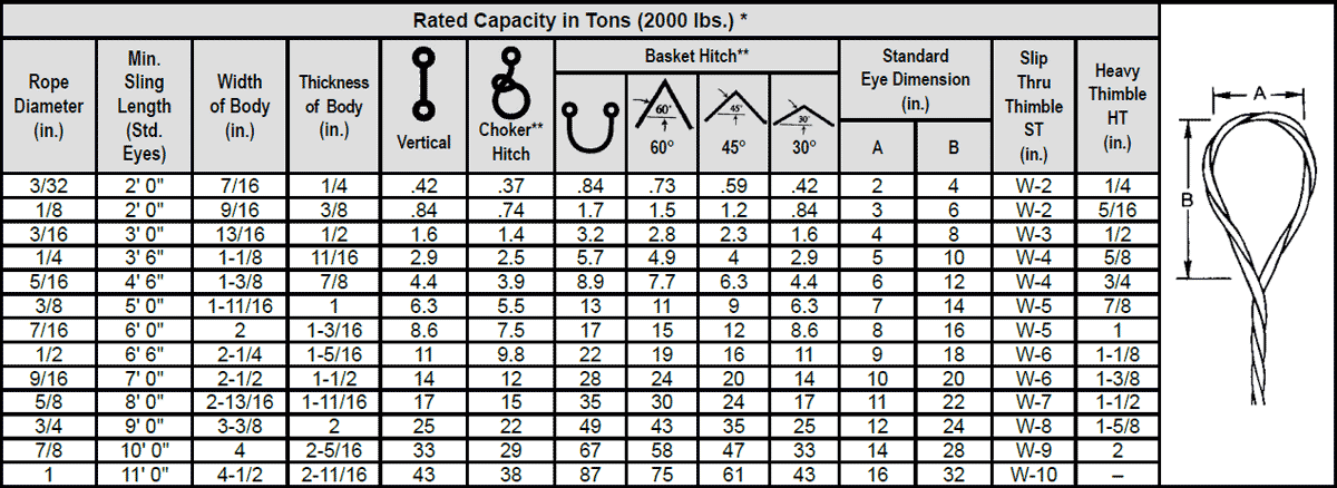
This is the length of wire rope between splices, sleeves or fittings. Generally, the minimum body length is equal to ten (10) times the sling body diameter. This allows approximately one and one half (1-1/2) rope lays between splices. For Multi-part slings, the minimum body length between splices is equal to forty (40) times the component rope diameter.
Large Loads Require Large Slings Whatever the load you are lifting. YuanBo Wire Rope Factory can supply a steel wire rope sling to do the task. Sling up to 12" (305mm) diameter can be supplied with minimum braking loads up to tons. There arethree distinct types of Wire Rope Sling.
Slings manufactured from cable laid ropes, 4" diameter to 12" diameter. hand spliced or by combination of hand splicing and socketing with eye at each end.
Slings manufactured from 6 strand equal laid ropes. up to 3.5 " diameter with soft eyes spliced each end. terminated by either hand splicing or mechanical means.
The most common size: wire rope slings having soft eyes at both end used for heavy lifting operations with safety factor of 7, length 6m, 12m, 16m, 20m, and the swl from 5 ton to 40 ton.
When a wire rope is bent around any sheave or other object there is a loss of strength due to this bending action. As the D/d ratio becomes smaller this loss of strength becomes greater and the rope becomes less efficient. This curve relates the efficiency of a rope diameter to different D/d ratios. This curve is based on static loads and applies to 6-strand class 6×19 and 6×37 wire rope.
When a sling is used in a BASKET- or CHOKER HITCH with D/d ratios smaller than listed in the capacity tables, the rated capacities (or WLLs) must be decreased.
For example: The BASKET and CHOKER hitch capacities listed (in all Standards and Regulations) for 6-strand ropes are based on a minimum D/d ratio of 25:1.
An object you place into a 1" diameter 6-strand wire rope sling using a basket- or choker hitch must have a minimum diameter of 25". If the object is smaller than the listed 25:1 D/d ratio the capacity (or WLL) must be decreased. Table A) illustrates the percentage of decrease to be expected.
If the object lifted with a 6-strand wire rope sling in a basket hitch is at least 25 x larger than the sling diameter (D/d 25:1) the basket capacity need not to be adjusted.
It is better to use a larger shackle or a Wide Body shackle type. If the shackle or object has at least 5x the sling diameter (D/d 5:1) the basket sling capacity must still be reduced by about 25%.
Load Hooks must have sufficient thickness to ensure proper sling D/d ratio, particularly when using slings in an inverted basket hitch; that is the sling BODY is placed into the hook and the sling EYES are facing downwards.
Endless (or Grommet) slings DO NOT HAVE A LOOP which has double the strength of the sling body. Prior to EVERY lift, YOU, the user, has to determine if the D/d ratio is equal or higher than the ones listed in the capacity tables.
Wire ropes are essential for safety purposes on construction sites and industrial workplaces. They are used to secure and transport extremely heavy pieces of equipment – so they must be strong enough to withstand substantial loads. This is why the wire rope safety factor is crucial.
You may have heard that it is always recommended to use wire ropes or slings with a higher breaking strength than the actual load. For instance, say that you need to move 50,000 lbs. with an overhead crane. You should generally use equipment with a working load limit that is rated for weight at least five times higher – or 250,000 lbs. in this case.
This recommendation is all thanks to the wire rope safety factor. This calculation is designed to help you determine important numbers, such as the minimum breaking strength and the working load limit of a wire rope.
The safety factor is a measurement of how strong of a force a wire rope can withstand before it breaks. It is commonly stated as a ratio, such as 5:1. This means that the wire rope can hold five times their Safe Work Load (SWL) before it will break.
So, if a 5:1 wire rope’s SWL is 10,000 lbs., the safety factor is 50,000 lbs. However, you would never want to place a load near 50,000 lbs. for wire rope safety reasons.
The safety factor rating of a wire rope is the calculation of the Minimum Break Strength (MBS) or the Minimum Breaking Load (MBL) compared to the highest absolute maximum load limit. It is crucial to use a wire rope with a high ratio to account for factors that could influence the weight of the load.
The Safe Working Load (SWL) is a measurement that is required by law to be clearly marked on all lifting devices – including hoists, lifting machines, and tackles. However, this is not visibly listed on wire ropes, so it is important to understand what this term means and how to calculate it.
The safe working load will change depending on the diameter of the wire rope and its weight per foot. Of course, the smaller the wire rope is, the lower its SWL will be. The SWL also changes depending on the safety factor ratio.
The margin of safety for wire ropes accounts for any unexpected extra loads to ensure the utmost safety for everyone involved. Every year there aredue to overhead crane accidents. Many of these deaths occur when a heavy load is dropped because the weight load limit was not properly calculated and the wire rope broke or slipped.
The margin of safety is a hazard control calculation that essentially accounts for worst-case scenarios. For instance, what if a strong gust of wind were to blow while a crane was lifting a load? Or what if the brakes slipped and the load dropped several feet unexpectedly? This is certainly a wire rope safety factor that must be considered.
Themargin of safety(also referred to as the factor of safety) measures the ultimate load or stress divided by theallowablestress. This helps to account for the applied tensile forces and stress thatcouldbe applied to the rope, causing it to inch closer to the breaking strength limit.
A proof test must be conducted on a wire rope or any other piece of rigging equipment before it is used for the first time.that a sample of a wire rope must be tested to ensure that it can safely hold one-fifth of the breaking load limit. The proof test ensures that the wire rope is not defective and can withstand the minimum weight load limit.
First, the wire rope and other lifting accessories (such as hooks or slings) are set up as needed for the particular task. Then weight or force is slowly added until it reaches the maximum allowable working load limit.
Some wire rope distributors will conduct proof loading tests before you purchase them. Be sure to investigate the criteria of these tests before purchasing, as some testing factors may need to be changed depending on your requirements.
When purchasing wire ropes for overhead lifting or other heavy-duty applications, understanding the safety dynamics and limits is critical. These terms can get confusing, but all of thesefactors serve an important purpose.
Our company has served as a wire rope distributor and industrial hardware supplier for many years. We know all there is to know about safety factors. We will help you find the exact wire ropes that will meet your requirements, no matter what project you have in mind.
The use of rope for any purpose results in friction, bending and tension. All rope, hardware, sheaves rollers, capstans, cleats, as well as knots are, in varying degrees, damaging to ropes. It’s important to understand that rope is a moving, working, strength member and even under the most ideal conditions will lose strength due to use in any application. Maximizing the safety of rope performance is directly related to how strength loss is managed and making sure ropes are retired from service before a dangerous situation is created. Ropes are serious working tools and used properly will give consistent and reliable service. The cost of rope replacement is extremely small when compared to the physical damage or personnel injury that can result from using a worn out rope.
There are basically three steps to consider in providing the longest possible service life for ropes, the safest conditions and long range economy: Selection, Usage and Inspection.
Selecting a rope involves evaluating a combination of factors. Some of these factors are straight forward, like comparing rope specifications. Others are less qualitative, like color preference or how a rope feels while handling. Cutting corners, reducing design factors, sizes or strengths on an initial purchase creates unnecessary replacements, potentially dangerous conditions and increased long term costs. Fiber and construction being equal, a larger rope will outlast a smaller rope, because of greater surface wear distribution. By the same token, a stronger rope will outlast a weaker one, because it will be used at a lower percentage of its break strength and corresponding Work Load Limit with less chance of overstressing. The following factors should be considered in your rope selection: Strength, Elongation, Firmness, Construction and Abrasion.
When given a choice between ropes, select the strongest of any given size. A load of 200 pounds represents 2% of the strength of a rope with a 10,000 Lbs. breaking strength. The same load represents 4% of the strength of a rope that has a 5,000 Lbs. breaking strength. The weaker rope will work harder and as a result will have to be retired sooner. Braided ropes are stronger than twisted ropes that are the same size and fiber type.
It is well accepted that ropes with lower elongation under load will give you better control. However, ropes with lower elongation that are shock loaded, like a lowering line, can fail without warning even though the rope appears to be in good shape. Low elongating ropes should be selected with the highest possible strength. Both twisted ropes and braided ropes are suitable for rigging. Size for size, braided rope has higher strength and lower stretch than a twisted rope of similar fiber. See page 390 for additional information on rope elongation.
Select ropes that are firm and hold their shape during use. Soft or mushy ropes will snag easily and abrade quickly causing accelerated strength loss.
Rope construction plays an important role in resistance to normal wear and abrasion. Braided ropes have a basically round, smooth construction that tends to flatten out somewhat over the bearing surface. Flattening distributes wear over a much greater area, as opposed to the crowns of a three strand or to a lesser degree, an eight strand rope.
All rope will be severely damaged if subjected to rough surfaces or damaging edges. All rope must be protected against damaging or abrasive surfaces. Wire rope will score and gouge chocks and bitts creating cutting edges that can damage synthetic ropes. Chocks, bitts, drums and other surfaces must be kept in good condition and free of burrs and rust. Weld beads on repaired capstans, fairleads, etc., are equally damaging, unless dressed down smoothly. Pulleys must be free to rotate and should be of proper size to avoid
Avoid using a rope that shows signs of aging and wear. If in doubt, do not use the rope. Damaged rope must be destroyed to prevent any future use. No visual inspection can be guaranteed to accurately and precisely determine the residual strength of the rope. When fibers show wear in any area, the damaged area must be removed and the rope should be re-spliced or replaced. Check regularly for frayed or broken strands. Pulled strands should be rethreaded into the rope if possible. A pulled strand can snag on a foreign object during usage. Both outer and inner rope fibers may contribute to the strength of the rope. When either is worn the rope is naturally weakened. Open the strand of the rope and inspect for powdered fiber, which is one sign of internal wear. A heavily used rope will often become compacted or hard, which indicates reduced strength. The rope should be discarded and made unusable if this condition is detected. See pages 395 and 396 for additional inspection information.
New rope tensile strength is based upon tests of new and unused spliced rope of standard construction in accordance with Samson testing methods, which conform to Cordage Institute, ASTM and OCIMF test procedures. It can be expected that strengths will decrease as soon as a rope is put into use. Because of the wide range of rope use, changes in rope conditions, exposure to the many factors affecting rope behavior and the possibility of risk to life and property, it is impossible to cover all aspects of proper rope applications or to make generalized statements as to Work Load Limits.
Work Load Limits are the load that a rope in good condition with appropriate splices in non-critical applications is subjected to during normal activity. They are normally expressed as a percentage of new rope strength and should not exceed 20% of the stated break strength. Thus, your maximum Work Load Limit would be 1/5 or 20% of the stated break strength.
A point to remember is that a rope may be severely overloaded or shock loaded in use without breaking. Damage and strength loss may have occurred without any visible indication. The next time the rope is used under normal Work Loads and conditions, the acquired weakness can cause it to break.
Normal Work Load Limits do not cover dynamic conditions such as shock loads or sustained loads, nor do they apply where life, limb or property are involved. In these cases a stronger rope must be used and/or a higher design factor applied.
Normal Work Load Limits are not applicable when rope is subjected to dynamic loading. Whenever a load is picked up, stopped, moved or swung there is increased force due to dynamic loading. The more rapidly or suddenly such actions occur, the greater the increase in the dynamic loading. In extreme cases, the force put on the rope may be two, three or many more times the normal Work Load involved. Examples of dynamic loading would be: towing applications, picking up a load on a slack line or using a rope to stop a falling object. Dynamic loading affects low elongation ropes like polyester to a greater degree than higher elongation, nylon ropes. Dynamic loading is also magnified on shorter length ropes when compared to longer rope lengths. Therefore, in all such applications, normal Work Load Limits do not apply.
Work Load Limits as described do not apply when ropes have been subjected to shock loading. Whenever a load is picked up, stopped, moved or swung, there is an increased force due to dynamic loading. The more rapidly or suddenly such actions occur, the greater this increase in force will be. The load must be handled slowly and smoothly to minimize dynamic effects. In extreme cases, the force put on the rope may be two, three or even more times the normal Work Load involved. Examples of shock loading are picking up a tow on a slack line or using a rope to stop a falling object. Therefore, in all applications such as towing lines, life lines, safety lines, climbing ropes, etc., design factors must reflect the added risks involved. Users should be aware that dynamic effects are greater on a low elongation rope such as manila than on a high-elongation rope such as nylon and greater on a shorter rope than on a longer one.
The shock load that occurs on a winch line when a 5,000 Lbs. object is lifted vertically with a sudden jerk may translate the 5,000 Lbs. of weight into 30,000 Lbs. of dynamic force, which could cause the line to break. Where shock loads, sustained loads or where life, limb or valuable property is involved, it is recommended that a much higher design factor than 5 be used.
Remember, shock loads are simply a sudden change in tension, from a state of relaxation or low load to one of high load. The further an object falls, the greater the impact. Synthetic fibers have a memory and retain the effects of being overloaded or shock loaded. Ropes that have been shock loaded can fail at a later time, when used within Work Load Limits.
Wire rope is often used in slings because of its strength, durability, abrasion resistance and ability to conform to the shape of the loads on which it is used. In addition, wire rope slings are able to lift hot materials.
Wire rope used in slings can be made of ropes with either Independent Wire Rope Core (IWRC) or a fiber-core. It should be noted that a sling manufactured with a fiber-core is usually more flexible but is less resistant to environmental damage. Conversely, a core that is made of a wire rope strand tends to have greater strength and is more resistant to heat damage.
Wire rope may be manufactured using different rope lays. The lay of a wire rope describes the direction the wires and strands are twisted during the construction of the rope. Most wire rope is right lay, regular lay. This type of rope has the widest range of applications. Wire rope slings may be made of other wire rope lays at the recommendation of the sling manufacturer or a qualified person.
Wire rope slings are made from various grades of wire rope, but the most common grades in use are Extra Improved Plow Steel (EIPS) and Extra Extra Improved Plow Steel (EEIPS). These wire ropes are manufactured and tested in accordance with ASTM guidelines. If other grades of wire rope are used, use them in accordance with the manufacturer"s recommendations and guidance.
When selecting a wire rope sling to give the best service, consider four characteristics: strength, ability to bend without distortion, ability to withstand abrasive wear, and ability to withstand abuse.
Rated loads (capacities) for single-leg vertical, choker, basket hitches, and two-, three-, and four-leg bridle slings for specific grades of wire rope slings are as shown in Tables 7 through 15.
Ensure that slings made of rope with 6×19 and 6x37 classifications and cable slings have a minimum clear length of rope 10 times the component rope diameter between splices, sleeves, or end fittings unless approved by a qualified person,
Ensure that braided slings have a minimum clear length of rope 40 times the component rope diameter between the loops or end fittings unless approved by a qualified person,
Do not use wire rope clips to fabricate wire rope slings, except where the application precludes the use of prefabricated slings and where the sling is designed for the specific application by a qualified person,
Ensure that wire rope slings have suitable characteristics for the type of load, hitch, and environment in which they will be used and that they are not used with loads in excess of the rated load capacities described in the appropriate tables. When D/d ratios (Fig. 4) are smaller than those listed in the tables, consult the sling manufacturer. Follow other safe operating practices, including:
When D/d ratios (see Fig. 6) smaller than those cited in the tables are necessary, ensure that the rated load of the sling is decreased. Consult the sling manufacturer for specific data or refer to the WRTB (Wire Rope Technical Board) Wire Rope Sling Users Manual, and
Before initial use, ensure that all new swaged-socket, poured-socket, turnback-eye, mechanical joint grommets, and endless wire rope slings are proof tested by the sling manufacturer or a qualified person.
Permanently remove from service fiber-core wire rope slings of any grade if they are exposed to temperatures in excess of 180 degrees F (82 degrees C).
Follow the recommendations of the sling manufacturer when you use metallic-core wire rope slings of any grade at temperatures above 400 degrees F (204 degrees C) or below minus 40 degrees F (minus 40 degrees C).


 8613371530291