
wire rope load calculation made in china
(a) Wire rope slings must be made from new or unused regular lay wire rope. The wire rope must be manufactured and tested in accordance with ASTM A 1023-02 and ASTM A 586.
(f) Wire rope clips, if used, must be installed and maintained in accordance with the recommendations of the clip manufacturer or a qualified person, or in accordance with the provisions of ASME B30.26-2010.
(g) You must not use slings made with wire rope clips as a choker hitch.Note:If using wire rope clips under these conditions, follow the guidance given in Table 5.
Number, Torque Values, and Turn Back Requirements for U-Bolt Wire Rope ClipsNumber, Torque Values, and Turn Back Requirements for Double Saddle (Fist Grip) Wire Rope Clips
•Slings made of rope with 6x19 and 6x36 classification.A minimum clear length of rope 10 times the rope diameter between splices, sleeves, or end fittings (see Figure 4, Minimum Sling Length) unless approved by a qualified person.
•Braided slings.A minimum clear length of rope 40 times the component rope diameter between the loops or end fittings (see Figure 5, Minimum Braided Sling Length) unless approved by a qualified person.
(b) You must rate slings with the load capacity of the lowest rated component of the sling. For example, if you use fittings that are rated lower than the sling material itself, identify the sling with the lower rated capacity.
(3) Identification information. All wire rope slings must have legible identification information attached to the sling which includes the information below, see sample tag in Figure 6. For slings in use that are manufactured before the effective date of this rule, the information below must be added before use or at the time the periodic inspection is completed.
Sample Wire Rope Sling ID TagNote:Sample tag for a 1/2" single-leg sling 6x19 or 6x36 classification, extra improved plow steel (EIPS) grade fiber core (FC) wire rope with a mechanical splice (ton = 2,000 lb).
(6) Proof load tests. You must make sure the sling manufacturer or a qualified person proof load tests the following slings before initial use, according to Table 8:
(c) For single- or multiple-leg slings and endless slings, each leg must be proof loaded according to the requirements listed in Table 8 based on fabrication method. The proof load test must not exceed 50% of the component ropes" or structural strands" minimum breaking strength;
•Swaged socket and poured socket slings.Each leg to at least two times, but not more than two and 1/2 times, the single-leg vertical hitch rated load.
Note: For mechanical splice, swaged socket and poured socket slings follow the rope manufacturer"s recommendations for proof load testing provided that it is within the above-specified proof load range, including (c) of this subsection.
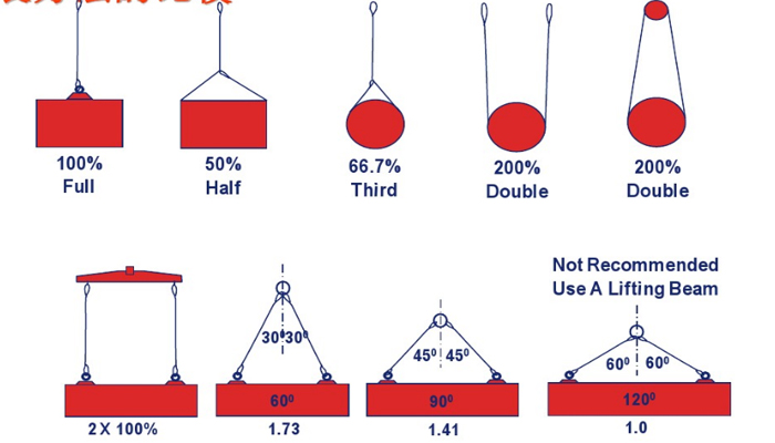
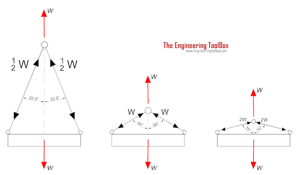
(a) You must use wire rope slings within the rated loads shown in Tables 7 through 15 in ASME B30.9-2010. For angles that are not shown in these tables, either use the rated load for the next lower angle or have a qualified person calculate the rated load.
(c) Rated loads for slings used in a choker hitch must conform to the values shown in the above referenced tables, provided that the angle of choke is 120 degrees or greater. See Figure 9 and Table 10, Angle of Choke.
(d) You must use either Figure 9 and Table 10, the manufacturer, or a qualified person to determine the rated load if the angle of choke in a choker hitch is less than 120 degrees.
(e) You must decrease the rated load of the sling when D/d ratios (Figure 8) smaller than 25 to one. Consult the sling manufacturer for specific data or refer to the Wire Rope Sling User"s Manual (wire rope technical board).

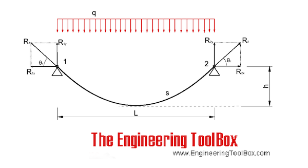
From Eqs. (2) to (6), it can be seen that given the tension T of one end cable, the horizontal component H and the cable shape y are coupled with each other. Thus, the unstressed cable length S0 can be determined by iterative calculation. In the calculation, the iterative parameter can be selected as the horizontal component force H, and its initial iterative value H0 is often taken as the component force of the tower end cable tension T along the chord line.
The force and load of the cable bridge can be applied according to the span and bridge width. Under the action of an external force, the external load of the main cable is equal per linear meter in the span direction, which agrees with the parabola theory. Therefore, the parabola thread shape theory can be used for the cable shape approximate analysis.
The approximate analytical algorithm assumes that the load and deformation of several main cables of the cable bridge are uniform, and it is equivalent to a single cable plane model, as shown in Fig. 1. It is assumed that the cable shape of the main span is parabolic, and both ends are hinged at the theoretical intersection points A and B of the main cable axis at the saddle. The influence of the horizontal dip angle and the sag of the main cable of the anchor span was ignored, and a horizontal cable force was used to replace the axial cable force of all sections of the anchor cable span and main span. Based on the relationship between the mechanical balance and the physical properties of the materials, according to the geometric conditions of equal cable suspension speed of the whole cable for the same cable bridge under any two load conditions, a cubic algebraic equation of horizontal cable force under the calculated load state is obtained. Finally, the main cable shape is obtained from the obtained balance conditions of the horizontal cable force and moment [11].
Wire rope is the sinew that enables winch muscle to be applied where it is needed. Wire rope positions the dredge, crowds the cutter into the solids bank and supports the ladder.
Table 9 below provides information on the strength of various sizes of one popular style of wire rope, 6 x 19 IWRC. The rope is made up of 6 strands, each of which is made up of from 16 to
A. LAY is the direction in which the strands “lay” as you look along a length of wire rope. Strands that veer to the right are RIGHT Lay. Strands that veer to the left are LEFT Lay. It makes no difference which way you look down the rope.
B. RELATIONSHIP has to do with the direction the strand wires lay in relation to the direction in which the strands lay. If the strand wires spiral in the direction opposite the direction the strands spiral the rope is REGULAR Lay. If the strand wires spiral in the same direction as the strands spiral the rope is LANG Lay.
The sketch below shows a typical dredge ladder rigging with a bail load of 50,000 lb. and how to determine the number of parts of line. The parts of line can be determined by counting the number of cable segments that run between the hoist block to the bail block. The parts of line determines the extent of the multiplying effect that makes it possible for a single line coming off the winch drum with a relatively small line pull to lift a heavy load. A friction factor must be applied along with the line part multiplier to calculate the actual lift capability.
Wire rope is often used in slings because of its strength, durability, abrasion resistance and ability to conform to the shape of the loads on which it is used. In addition, wire rope slings are able to lift hot materials.
Wire rope used in slings can be made of ropes with either Independent Wire Rope Core (IWRC) or a fiber-core. It should be noted that a sling manufactured with a fiber-core is usually more flexible but is less resistant to environmental damage. Conversely, a core that is made of a wire rope strand tends to have greater strength and is more resistant to heat damage.
Wire rope may be manufactured using different rope lays. The lay of a wire rope describes the direction the wires and strands are twisted during the construction of the rope. Most wire rope is right lay, regular lay. This type of rope has the widest range of applications. Wire rope slings may be made of other wire rope lays at the recommendation of the sling manufacturer or a qualified person.
Wire rope slings are made from various grades of wire rope, but the most common grades in use are Extra Improved Plow Steel (EIPS) and Extra Extra Improved Plow Steel (EEIPS). These wire ropes are manufactured and tested in accordance with ASTM guidelines. If other grades of wire rope are used, use them in accordance with the manufacturer"s recommendations and guidance.
When selecting a wire rope sling to give the best service, consider four characteristics: strength, ability to bend without distortion, ability to withstand abrasive wear, and ability to withstand abuse.
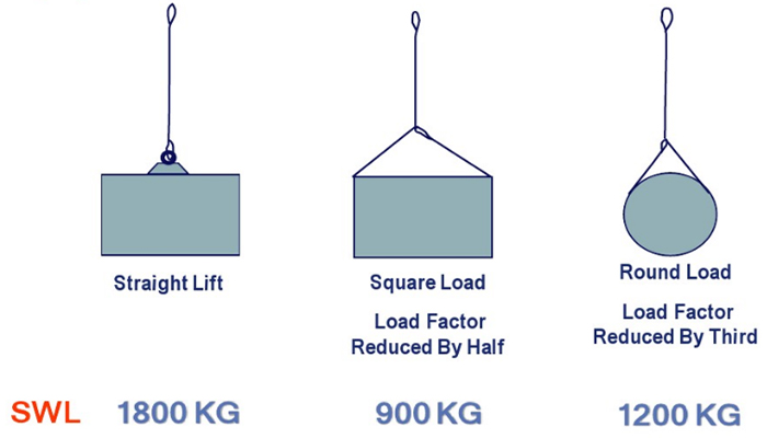
Rated loads (capacities) for single-leg vertical, choker, basket hitches, and two-, three-, and four-leg bridle slings for specific grades of wire rope slings are as shown in Tables 7 through 15.
Rated loads for a sling in a choker hitch are the values shown in Table 7, 9, 11, 13, 14, or 15, provided that the angle of the choke is 120 degrees or more (Fig. 2). Use the values in Fig. 2 or those from the sling manufacturer or a qualified person for angles of choke less than 120 degrees.
Ensure that slings made of rope with 6×19 and 6x37 classifications and cable slings have a minimum clear length of rope 10 times the component rope diameter between splices, sleeves, or end fittings unless approved by a qualified person,
Ensure that braided slings have a minimum clear length of rope 40 times the component rope diameter between the loops or end fittings unless approved by a qualified person,
Do not use wire rope clips to fabricate wire rope slings, except where the application precludes the use of prefabricated slings and where the sling is designed for the specific application by a qualified person,
Ensure that wire rope slings have suitable characteristics for the type of load, hitch, and environment in which they will be used and that they are not used with loads in excess of the rated load capacities described in the appropriate tables. When D/d ratios (Fig. 4) are smaller than those listed in the tables, consult the sling manufacturer. Follow other safe operating practices, including:
Ensure that multiple-leg slings are selected according to Tables 7 through 15 when used at the specific angles given in the tables. Ensure that operations at other angles are limited to the rated load of the next lower angle given in the tables or calculated by a qualified person,
When D/d ratios (see Fig. 6) smaller than those cited in the tables are necessary, ensure that the rated load of the sling is decreased. Consult the sling manufacturer for specific data or refer to the WRTB (Wire Rope Technical Board) Wire Rope Sling Users Manual, and
Ensure that all portions of the human body are kept away from the areas between the sling and the load and between the sling and the crane or hoist hook,
When using a basket hitch, ensure that the legs of the sling contain or support the load from the sides, above the center of gravity, so that the load remains under control,
Ensure that the load applied to the hook is centered in the base (bowl) of the hook to prevent point loading on the hook, unless the hook is designed for point loading,
Before initial use, ensure that all new swaged-socket, poured-socket, turnback-eye, mechanical joint grommets, and endless wire rope slings are proof tested by the sling manufacturer or a qualified person.
Permanently remove from service fiber-core wire rope slings of any grade if they are exposed to temperatures in excess of 180 degrees F (82 degrees C).
Follow the recommendations of the sling manufacturer when you use metallic-core wire rope slings of any grade at temperatures above 400 degrees F (204 degrees C) or below minus 40 degrees F (minus 40 degrees C).
Original equipment wire rope and replacement wire rope must be selected and installed in accordance with the requirements of this section. Selection of replacement wire rope must be in accordance with the recommendations of the wire rope manufacturer, the equipment manufacturer, or a qualified person.
Wire rope design criteria: Wire rope (other than rotation resistant rope) must comply with either Option (1) or Option (2) of this section, as follows:
Option (1). Wire rope must comply with section 5-1.7.1 of ASME B30.5-2004 (incorporated by reference, see § 1926.6) except that section"s paragraph (c) must not apply.
Option (2). Wire rope must be designed to have, in relation to the equipment"s rated capacity, a sufficient minimum breaking force and design factor so that compliance with the applicable inspection provisions in § 1926.1413 will be an effective means of preventing sudden rope failure.
Type I rotation resistant wire rope ("Type I"). Type I rotation resistant rope is stranded rope constructed to have little or no tendency to rotate or, if guided, transmits little or no torque. It has at least 15 outer strands and comprises an assembly of at least three layers of strands laid helically over a center in two operations. The direction of lay of the outer strands is opposite to that of the underlying layer.
Type II rotation resistant wire rope ("Type II"). Type II rotation resistant rope is stranded rope constructed to have significant resistance to rotation. It has at least 10 outer strands and comprises an assembly of two or more layers of strands laid helically over a center in two or three operations. The direction of lay of the outer strands is opposite to that of the underlying layer.
Type III rotation resistant wire rope ("Type III"). Type III rotation resistant rope is stranded rope constructed to have limited resistance to rotation. It has no more than nine outer strands, and comprises an assembly of two layers of strands laid helically over a center in two operations. The direction of lay of the outer strands is opposite to that of the underlying layer.
Type I must have an operating design factor of no less than 5, except where the wire rope manufacturer and the equipment manufacturer approves the design factor, in writing.
A qualified person must inspect the rope in accordance with § 1926.1413(a). The rope must be used only if the qualified person determines that there are no deficiencies constituting a hazard. In making this determination, more than one broken wire in any one rope lay must be considered a hazard.
Each lift made under § 1926.1414(e)(3) must be recorded in the monthly and annual inspection documents. Such prior uses must be considered by the qualified person in determining whether to use the rope again.
Rotation resistant ropes may be used as boom hoist reeving when load hoists are used as boom hoists for attachments such as luffing attachments or boom and mast attachment systems. Under these conditions, all of the following requirements must be met:
The requirements in ASME B30.5-2004 sections 5-1.3.2(a), (a)(2) through (a)(4), (b) and (d) (incorporated by reference, see § 1926.6) except that the minimum pitch diameter for sheaves used in multiple rope reeving is 18 times the nominal diameter of the rope used (instead of the value of 16 specified in section 5-1.3.2(d)).
The operating design factor for these ropes must be the total minimum breaking force of all parts of rope in the system divided by the load imposed on the rope system when supporting the static weights of the structure and the load within the equipment"s rated capacity.
Wire rope clips used in conjunction with wedge sockets must be attached to the unloaded dead end of the rope only, except that the use of devices specifically designed for dead-ending rope in a wedge socket is permitted.
Prior to cutting a wire rope, seizings must be placed on each side of the point to be cut. The length and number of seizings must be in accordance with the wire rope manufacturer"s instructions.


 8613371530291