
wire rope load calculation quotation
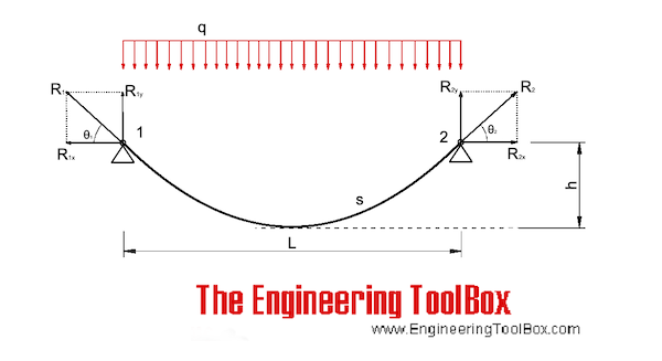
The equations below can also be used for cables only loaded with their own weight as long as the sagging height (h) vs. length (L) ratio is below 0.1.
The calculator below can be used for cables with inclined chords and uniformly loads. The calculator is based on an iterative algorithm where the parable shaped cable is adapted to span L, height h1 and h2 according the figure above. The parable equation estimated below can be used to replicate the shape in spreadsheets or CAD systems.

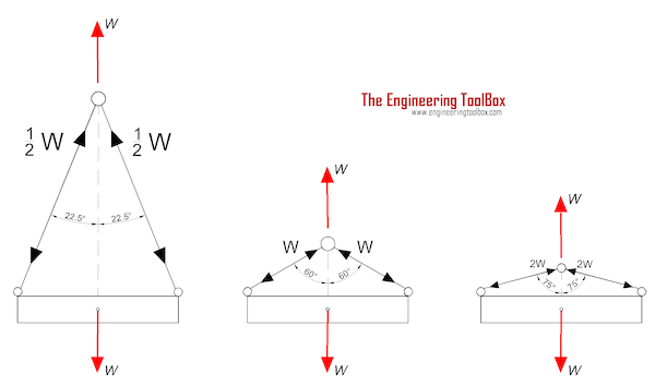
If you are performing calculations involving the load of bridles and basket hitches, it’s important to use a wire rope sling capacity chart and also remember that as a reduction in the horizontal angle of the sling occurs the load imposed upon each leg increases. With bridles consisting of three or more legs, the horizontal angle is measured in the same manner as it is for horizontal sling angles consisting of two legged hitches. Different angles may result if a bridle consists of different leg lengths. The load supported by each leg must be determined based on the location of the center of gravity of the lift in the position of the slings.
At Kennedy Wire Rope & Sling Co., Inc., we provide high quality wire rope sling components and can help you determine the capacity of your wire rope sling arrangement.
The standard choke angle is about 135 degrees when a load is hanging free. However, using a choker hitch to lift internal load can produce a significant bend at the choke. It’s important to reduce a hitches rated capacity when it is used at an angle smaller than 120 degrees. As is evident from a wire rope sling capacity chart, the rated capacity of a wire rope sling must be adjusted when using a choker hitch to turn, shifts, or control the load. The rated capacity must also be adjusted when, in a multi-leg lift, the pull is against the choke.
Using choker hitches at angles of 135° or greater is not recommended due to the instability produced with this arrangement. In addition to consulting with a wire rope sling capacity chart, considerable care should also be taken to ensure that the choke angle is determined and applied as accurately as possible.
Rope strength is a misunderstood metric. One boater will talk about tensile strength, while the other will talk about working load. Both of these are important measurements, and it’s worth learning how to measure and understand them. Each of these measurements has different uses, and here we’re going to give a brief overview of what’s what. Here’s all you need to know about rope strength.
Each type of line, natural fiber, synthetic and wire rope, have different breaking strengths and safe working loads. Natural breaking strength of manila line is the standard against which other lines are compared. Synthetic lines have been assigned “comparison factors” against which they are compared to manila line. The basic breaking strength factor for manila line is found by multiplying the square of the circumference of the line by 900 lbs.
Just being able to calculate breaking strength doesn’t give one a safety margin. The breaking strength formula was developed on the average breaking strength of a new line under laboratory conditions. Without straining the line until it parts, you don’t know if that particular piece of line was above average or below average. For more information, we have discussed the safe working load of ropes made of different materials in this article here.
It’s very important to understand the fundamental differences between the tensile strength of a rope, and a rope’s working load. Both terms refer to rope strength but they’re not the same measurement.
A rope’s tensile strength is the measure of a brand-new rope’s breaking point tested under strict laboratory-controlled conditions. These tests are done by incrementally increasing the load that a rope is expected to carry, until the rope breaks. Rather than adding weight to a line, the test is performed by wrapping the rope around two capstans that slowly turn the rope, adding increasing tension until the rope fails. This test will be repeated on numerous ropes, and an average will be taken. Note that all of these tests will use the ASTM test method D-6268.
The average number will be quoted as the rope’s tensile strength. However, a manufacturer may also test a rope’s minimum tensile strength. This number is often used instead. A rope’s minimum tensile strength is calculated in the same way, but it takes the average strength rating and reduces it by 20%.
A rope’s working load is a different measurement altogether. It’s determined by taking the tensile strength rating and dividing it accordingly, making a figure that’s more in-line with an appropriate maximum load, taking factors such as construction, weave, and rope longevity into the mix as well. A large number of variables will determine the maximum working load of a rope, including the age and condition of the rope too. It’s a complicated equation (as demonstrated above) and if math isn’t your strong point, it’s best left to professionals.
However, if you want to make an educated guess at the recommended working load of a rope, it usually falls between 15% and 25% of the line’s tensile strength rating. It’s a lotlower than you’d think. There are some exceptions, and different construction methods yield different results. For example, a Nylon rope braided with certain fibers may have a stronger working load than a rope twisted out of natural fibers.
For safety purposes, always refer to the information issued by your rope’s manufacturer, and pay close attention to the working load and don’t exceed it. Safety first! Always.
If you’re a regular sailor, climber, or arborist, or just have a keen interest in knot-tying, be warned! Every knot that you tie will reduce your rope’s overall tensile strength. Some knots aren’t particularly damaging, while others can be devastating. A good rule of thumb is to accept the fact that a tied knot will reduce your rope’s tensile strength by around 50%. That’s an extreme figure, sure, but when it comes to hauling critical loads, why take chances?
Knots are unavoidable: they’re useful, practical, and strong. Splices are the same. They both degrade a rope’s strength. They do this because a slight distortion of a rope will cause certain parts of the rope (namely the outer strands) to carry more weight than others (the inner strand). In some cases, the outer strands end up carrying all the weight while the inner strands carry none of it! This isn’t ideal, as you can imagine.
Some knots cause certain fibers to become compressed, and others stretched. When combined together, all of these issues can have a substantial effect on a rope’s ability to carry loads.
Naturally, it’s not always as drastic as strength loss of 50% or more. Some knots aren’t that damaging, some loads aren’t significant enough to cause stress, and some rope materials, such as polypropylene, Dyneema, and other modern fibers, are more resilient than others. Just keep in mind that any knots or splices will reduce your rope’s operations life span. And that’s before we talk about other factors such as the weather or your rope care regime…
SWL, NWL, MBS — all of the acronyms can get very confusing. Don’t fret – we’re here to clear things up when it comes to safe working load limits and the terms associated with it.
Safe Working Load (SWL) sometimes stated as the Normal Working Load (NWL) is the mass or force that a piece of lifting equipment, lifting device or accessory can safely utilize to lift, suspend, or lower a mass without fear of breaking. Usually marked on the equipment by the manufacturer and is often 1/5 of the Minimum Breaking Strength (MBS) although other fractions may be used such as 1/4, 1/6 and 1/10.[1][2][3]
Other synonyms include Working Load Limit (WLL), which is the maximum working load designed by the manufacturer. This load represents a force that is much less than that required to make the lifting equipment fail or yield, also known as the Minimum Breaking Load (MBL). SWL or WLL are calculated by dividing MBL by a safety factor (SF). An example of this would be a chain that has a MBL of 2000 lbf (8.89 kN) would have a SWL or WLL of 400 lbf (1.78 kN) if a safety factor of 5 (5:1, 5 to 1, or 1/5) is used.
Here at Industrial Rope Supply, we are not only committed to providing you with a quality product, but also with all the information needed to insure safety comes first on every job. Have safety questions on a product purchased from us? Contact us today and we’ll be happy to talk you through and/or provide you with the safety materials needed.

While it is virtually impossible to calculate the precise length of wire rope that can be spooled on a reel or drum, the following provides a sufficiently close approximation.
* This formula is based on uniform rope winding on the reel. It will not give correct results if the winding is non-uniform. The formula also assumes that there will be the same number of wraps in each layer. While this is not strictly correct, there is no appreciable error in the result unless the traverse of the reel is quite small relative to the flange diameter (“H”).
** The values given for “K” factors take normal rope oversize into account. Clearance (“x”) should be about 2 inches unless rope-end fittings require more.
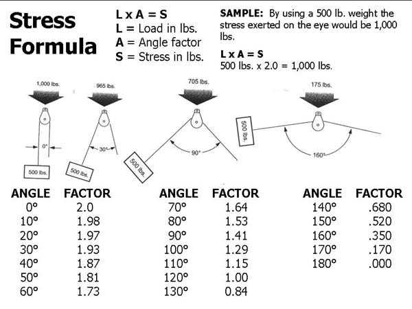
Block Division, Inc., has established through an accredited testing laboratory the capacity at which our products may be safely used. This may be defined as the safe working load limit, a chain or cable rope pulley block load calculation, or a force calculator. The safe working load limit (mechanical advantage) is the maximum load in pounds which should ever be applied, and when the load is applied uniformly and in direct tension to a straight segment of wire rope. By changing the degree of angle between lead and load angle, this also affects the stress on the block. The stress on the eye may be decreased by increasing the angle between the load and the lead angle. See chart 1 and illustration below.
Safe Work Load Limit: This is the maximum load (in lbs.) which can be applied to the Block and which has been established by Block Division, INC. (Load Capacity)
Working Load Limit (WLL) is the maximum working load designed by the manufacturer. This load represents a force that is much less than that required to make the lifting equipment fail or yield. The WLL is calculated by dividing the breaking load limit (BLL) by a safety factor (SF). An example of this would be a chain that has a BL of 2,000 lb. WLL of 400 lb. if a safety factor of 5 (5:1, 5 to 1, or 1/5) is used.
In any cable or wire rope application, stretch may be a concern. There are two forms of stretch in cable and wire rope: Structural Stretch and Elastic Stretch.
Structural stretch is the lengthening of the lay in the construction of cable and wire rope as the individual wires adjust under load. Structural stretch in Loos and Company products is less than 1% of the total cable length. This form of stretch can be completely removed by applying a cable or wire rope prestretching operation prior to shipment.
Elastic stretch is the actual physical elongation of the individual wires under load. The elastic stretch can be calculated by using the following formula*:
Any assembly of steel wires spun into a helical formation, either as a strand or wire rope, when subjected to a tensile load, can extend in three separate phases, depending on the magnitude of the applied load. There are also other factors which produce rope extension which are very small and can normally be ignored.
At the commencement of loading a new rope, extension is created by the bedding down of the assembled wires with a corresponding reduction in overall diameter. This reduction in diameter is accommodated by a lengthening of the helical lay. When sufficiently large bearing areas have been generated on adjacent wires to withstand the circumferential compressive loads, this mechanically created extension ceases and the extension in Phase 2 commences. The Initial Extension of any rope cannot be accurately determined by calculation and has no elastic properties.
The practical value of this characteristic depends upon many factors, the most important being the type and construction of rope, the range of loads and the number and frequency of the cycles of operation. It is not possible to quote exact values for the various constructions of rope in use, but the following approximate values may be employed to give reasonably accurate results.
Following Phase 1, the rope extends in a manner which complies approximately with Hookes Law (stress is proportional to strain) until the Limit of Proportionality or Elastic Limit is reached. It is important to note that wire ropes do not possess a Young’s Modulus of Elasticity, but an ‘apparent’ Modulus of Elasticity can be determined between two fixed loads.
The Modulus of Elasticity also varies with different rope constructions, but generally increases as the cross-sectional area of steel increases. By using the values given, it is possible to make a reasonable estimate of elastic extension, but if greater accuracy is required it is advisable to carry out a modulus test on an actual sample of the rope. As rope users will find it difficult to calculate the actual metallic steel area , the values can be found in the Wire Rope Users Manual or obtained from Bridon Engineering.
The permanent, non-elastic extension of the steel caused by tensile loads exceeding the yield point of the material. If the load exceeds the Limit of Proportionality, the rate of extension will accelerate as the load is increased, until a loading is reached at which continuous extension will commence, causing the wire rope to fracture without any further increase of load.
The coefficient of linear expansion (∝) of steel wire rope is (6.94 x10⁻⁶ per oF) and therefore the change in length of 1 foot of rope produced by a temperature change of t (oF) would be:
Example: What will be the total elongation of a 200 Ft length of 11/8" diameter Blue Strand 6x41 IWRC wire rope at a tension of 20,000 Ibs and with an increase in temperature of 20oF.
In addition to bending stresses experienced by wire ropes operating over sheaves or pulleys, ropes are also subjected to radial pressure as they make contact with the sheave. This pressure sets up shearing stresses in the wires, distorts the rope’s structure and affects the rate of wear of the sheave grooves. When a rope passes over a sheave, the load on the sheave bearing results from the tension in the rope and the angle of rope contact. It is independent of the diameter of the sheave.
Assuming that the rope is supported in a well fitting groove, then the pressure between the rope and the groove is dependent upon the rope tension and diameter but is independent of the arc of contact.
It must be realized that this method of estimation of pressure assumes that the area of contact of the rope in the groove is on the full rope diameter, whereas in fact only the crowns of the outer wires are actually in contact with the groove. It is estimated that the local pressures at these contact points may be as high as five times those calculated.
If the pressure is high, the compressive strength of the material in the groove may be insufficient to prevent excessive wear and indentation and this in turn will damage the outer wires of the rope and effect its working life. As with bending stresses, stresses due to radial pressure increase as the diameter of the sheave decreases.
Although high bending stresses generally call for the use of flexible rope constructions having relatively small diameter outer wires, these have less ability to withstand heavy pressures than do the larger wires in the less flexible constructions. If the calculated pressures are too high for the particular material chosen for the sheaves or drums or indentations are being experienced, consideration should be given to an increase in sheave or drum diameter. Such a modification would not only reduce the groove pressure, but would also improve the fatigue life of the rope.
The pressure of the rope against the sheave also causes distortion and flattening of the rope structure. This can be controlled by using sheaves with the correct groove profile which, for general purposes, suggests a recommended groove diameter of nominal rope diameter +6%. The profile at the bottom of the groove should be circular over an angle of approximately 120o, and the angle of flare between the sides of the sheave should be approximately 52o.
Bend fatigue testing of ropes usually consists of cycling a length of rope over a sheave while the rope is under a constant tension. As part of its ongoing development program BRIDON has tested literally thousands of ropes in this manner over the years on its in-house own design bend testing equipment.
Through this work, BRIDON has been able to compare the effects of rope construction, tensile strength, lay direction, sheave size, groove profile and tensile loading on bend fatigue performance under ideal operating conditions. At the same time it has been possible to compare rope life to discard criteria (e.g. as laid down in ISO 4309) with that to complete failure of the rope, i.e. to the point where the rope has been unable to sustain the load any longer. As part of the exercise, it has also been possible to establish the residual breaking strength of the rope at discard level of deterioration.
What needs to be recognized, however, is that very few ropes operate under these controlled operating conditions, making it very difficult to use this base information when attempting to predict rope life under other conditions. Other influencing factors, such as dynamic loading, differential loads in the cycle, fleet angle, reeving arrangement, type of spooling on the drum, change in rope direction, sheave alignment, sheave size and groove profile, can have an equally dramatic effect on rope performance.
However, the benefit of such testing can be particularly helpful to the rope manufacturer when developing new or improving existing products. If designers or operators of equipment are seeking optimum rope performance or regard bending fatigue life as a key factor in the operation of equipment, such information can be provided by BRIDON for guidance purposes.
Under certain circumstances it may be necessary to use a swivel in a lifting system to prevent rotation of the load. This is typically done for employee safety considerations. It is possible however, that the use of a swivel will have an adverse affect on rope performance and may in some cases damage the wire rope.
There are many types of accessories available that incorporate different types and degrees of rotation preventing swivels. The swivel may be either an independent accessory or an integral part of a lifting device such as a crane block with a swivel hook. A typical independent accessory is a ball bearing anti- friction swivel. There are also headache balls with swivel hooks. The type of swivel that causes the most concern from the standpoint of the wire rope is the independent anti-friction swivel that attaches directly to the rope. The purpose of using a swivel in a lifting system is to prevent rotation of the load. This then allows the wire rope to rotate. Excessive rope rotation can damage a wire rope.
To assist in determining whether or not a swivel should be used in the lifting system, the following recommendations should be considered. It must also be recognized that the rotation characteristics of different types and constructions of wire rope vary considerably. The following types and constructions of wire rope are grouped according to their rotation characteristics.
Wire rope constructions having very high rotation characteristics should not be used with a swivel under any circumstances. These rope constructions will rotate excessively with one end free to rotate and the rope will unlay and distort and be easily damaged with a loss of rope breaking force.
Wire rope constructions having high rotation characteristics when used in single part reeving may require a swivel in the system to prevent rotation in certain operating conditions. However, this should be done only when employee safety is the issue.
These rope constructions when used in a reeving system with one end free to rotate will have a high level of rotation. This will cause the rope to unlay to some degree and distortion of the rope will occur.
The ropes in this Group are designed with an inner rope that is laid in the opposite direction to the outer strands to provide a medium resistance to rotation. Ropes with medium rotation characteristics are used with a swivel in single part reeving applications. However, a swivel is not recommended for multiple part hoisting applications or in any application where the swivel is not necessary for safety reasons. If it is necessary to use a swivel the rope must be operating within the design factor of 5, must not be shock loaded and must be inspected daily by a qualified person for distortion.
It should be noted that if a swivel is used in conjunction with Group 3a ropes, rope service life might be reduced due to increased internal wear between the outer strands and the inner rope.
Wire ropes having low rotation characteristics used in either single or multiple part reeving may be used with a swivel. The reason for this is that the ropes will exhibit very little, if any, rotation when used at the proper design factor. Application parameters such as a fleet angle may induce turn into a wire rope that can be relieved by the use of a swivel. However, if the application does not induce any turn into the rope or if a swivel is not beneficial to the performance of the rope the swivel may not be necessary.
Of all the factors which have some influence on the winding of a rope on a smooth drum, the fleet angle, arguably, has the greatest effect. Fleet angle is usually defined as the included angle between two lines, one which extends from a fixed sheave to the flange of a drum and the other which extends from the same fixed sheave to the drum in a line perpendicular to the axis of the drum. (See illustration).
If the drum incorporates helical grooving, the helix angle of the groove needs to be added or subtracted from the fleet angle as described above to determine the actual fleet angle experienced by the rope.
When spooling rope onto a drum it is generally recommended that the fleet angle is limited to between 0.5O and 2.5O. If the fleet angle is too small, i.e. less than 0.5O, the rope will tend to pile up at the drum flange and fail to return across the drum. In this situation, the problem may be alleviated by introducing a ‘kicker’ device or by increasing the fleet angle through the introduction of a sheave or spooling mechanism.
If the rope is allowed to pile up it will eventually roll away from the flange creating a shock load in both the rope and the structure of the mechanism, an undesirable and unsafe operating condition. Excessively high fleet angles will return the rope across the drum prematurely, creating gaps between wraps of rope close to the flanges as well as increasing the pressure on the rope at the cross-over positions.
Even where helical grooving is provided, large fleet angles will inevitably result in localized areas of mechanical damage as the wires ‘pluck’ against each other. This is often referred to as ‘interference’ but the amount can be reduced by selecting a Langs lay rope if the reeving allows.
The “interference” effect can also be reduced by employing a Dyform rope which offers a much smoother exterior surface than conventional rope constructions. Floating sheaves or specially designed fleet angle compensating devices may also be employed to reduce the fleet angle effect.
Where a fleet angle exists as the rope enters a sheave, it initially makes contact with the sheave flange. As the rope continues to pass through the sheave it moves down the flange until it sits in the bottom of the groove. In doing so, even when under tension, the rope will actually roll as well as slide. As a result of the rolling action the rope is twisted, i.e. turn is induced into or out of the rope, either shortening or lengthening the lay length of the outer layer of strands. As the fleet angle increases so does the amount of twist.
To reduce the amount of twist to an acceptable level the fleet angle should be limited to 2.5O for grooved drums and 1.5O for plain drums and when using Rotation Resistant, ropes the fleet angle should be limited to 1.5O. However, for some crane and hoist applications it is recognized that for practical reasons it is not always possible to comply with these general recommendations, in which case the rope life could be affected.
The problem of torsional instability in crane hoist ropes would not exist if the ropes could be perfectly torque balanced under load. The torque generated in a wire rope under load is usually directly related to the applied load by a constant ‘torque factor’. For a given rope construction the torque factor can be expressed as a proportion of the rope diameter and this has been done below.
Variation with rope construction is relatively small and hence the scope for dramatically changing the stability of a hoisting system is limited. Nevertheless the choice of the correct rope can have a deciding influence, especially in systems which are operating close to the critical limit. It should be noted that the rope torque referred to here is purely that due to tensile loading. No account is taken of the possible residual torque due, for example, to rope manufacture or installation procedures.
Torsional Stability and the Cabling Graph (see page 78) are two methods which can be used to determine torsional stability or the tendency of the rope to cable. The torque factors quoted on page 79 are approximate maximum values for the particular constructions. To calculate the torque value for a particular rope size multiply by the nominal rope diameter. Example: for 20mm dia. Dyform 34LR at 20% of minimum breaking force:
The torsional characteristics of wire rope will have the effect of causing angular displacement of a sheave block when used in multi-fall reeving arrangements. The formula below gives a good approximation under such arrangements.
The preceding equations are all relative to a simple two part reeving. For more complex systems a similar approach may be used if account is taken of the different spacing of the ropes.
Even Number of Falls Note: For hoisting arrangements in which the rope falls are not parallel an average rope spacing should be used. Uneven Number of Falls
The equations assume that rope is torque-free in the noload condition, therefore, induced torque during or immediately after installation will adversely influence the calculated effect.
The above data assumes a constant torque value which is a valid assumption for a new rope. Wear and usage can have a significant effect on the torque value but practical work shows that under such circumstances the torque value will diminish, thus improving the stability of the arrangement.
Assuming a pedestal crane working on two falls is roped with 20mm diameter DYFORM 34LR and the bottom block carries a sheave of 360mm diameter with the falls parallel:
If the rope is new (worst condition) and no account is taken of block weight and friction then angular displacement for a height of lift of 30 meters is given by sin è = (4 000 . 30 . 0.152)

D/d Ratio is the ratio of the diameter (D) around the object which a sling is bent, divided by the sling’s overall diameter (d). More simply stated, it’s the diameter of a load or rigging hardware divided by the diameter of the sling.
Specific to polyester round slings, it varies among manufacturers, but usually, they recommend minimum hardware diameters to protect the inner core yarns. The illustration above provides an example of minimum shackle size requirements when using round slings. Bear in mind that round slings are more negatively affected by users bunching up the sling and not allowing the yarns to spread out properly and disperse the load when in a choker configuration.
Using choker hitches may save headroom; however, even following manufacturer-specified hardware diameter, the sling’s rated capacity reduces to 75% of the listed vertical rating. Failing to understand this relationship often results in overloading the sling.


 8613371530291