
wire rope load calculator for sale
With nearly 4,000 employees worldwide, WireCo WorldGroup is a great place for you to build a rewarding career. Our professionals enjoy the opportunities of a global manufacturing and distribution leader as well as a culture of open communication, professional growth, and friendly camaraderie that fosters innovation and problem solving.
Stren-Flex® manufactures an extensive line of high quality lifting slings and protective rigging gear to ensure a safe lifting experience. Our nylon and polyester web slings and roundslings are made in the USA and manufactured with care to meet or exceed OSHA and ASME standards. Our Simian® GT roundslings have the highest capacity ratings per color code in the industry and our Simian® Ultra High Performance Fiber roundslings offer advanced strength to weight ratios for extreme heavy lifting. We also offer a wide variety of cargo control tie downs, chain slings, wire rope slings, and rigging hardware.
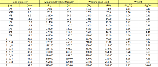
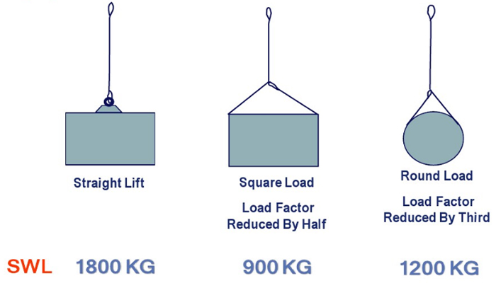
Enter the diameter of the wire rope, in mm, into the calculator to determine the safe working load (SWL). This calculator is for education purposes only, follow manufacturing guidelines for true SWL values.
A safe working load of a wire rope is a measure of the total load or weight that a wire rope can safely support during operation. Values greater than the SWL could result in a failure of the rope.
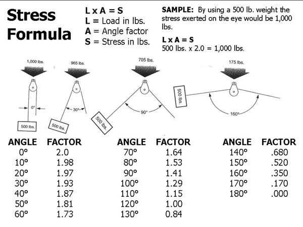
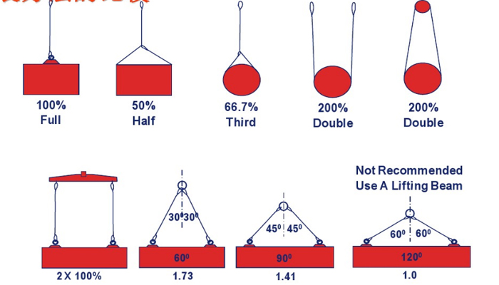
Block Division, Inc., has established through an accredited testing laboratory the capacity at which our products may be safely used. This may be defined as the safe working load limit, a chain or cable rope pulley block load calculation, or a force calculator. The safe working load limit (mechanical advantage) is the maximum load in pounds which should ever be applied, and when the load is applied uniformly and in direct tension to a straight segment of wire rope. By changing the degree of angle between lead and load angle, this also affects the stress on the block. The stress on the eye may be decreased by increasing the angle between the load and the lead angle. See chart 1 and illustration below.
Safe Work Load Limit: This is the maximum load (in lbs.) which can be applied to the Block and which has been established by Block Division, INC. (Load Capacity)
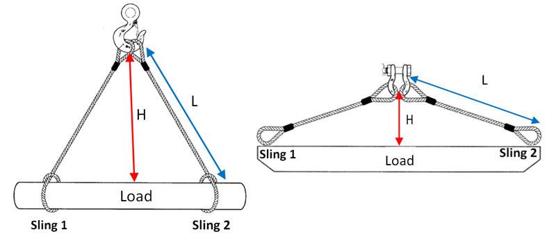
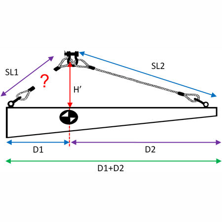
The end fittings at the load will see the same force as the sling connected to it, and they must also be adequate for their intended use. Please consult Northern Strands order desk for capacities with the use of hardware, or the addition of a top Masterlink.
The Lift-All® Sling/Leg Length Calculator has been designed to assist you in selecting the appropriate size slings for your lifting applications. It is your responsibility to assure that the slings you use are appropriate for your application.
You understand that the calculator provided is for general sling length and size suggestions. You agree that your ultimate purchase and use of Lift-All slings must be determined by you to be appropriate for your specific applications. Lift-All makes no guarantees that the information provided in the calculator is correct.
The end fittings at the load will see the same force as the sling connected to it, and they must also be adequate for their intended use. Please consult Northern Strands order desk for capacities with the use of hardware, or the addition of a top Masterlink.
Structural Stretch is the lengthening of the lay in the construction of cable and wire rope as the individual wires adjust under load. Structural Stretch in Loos & Co., Inc. products is less than 1% of the total cable length. This form of stretch can be completely removed by applying a cable or wire rope prestretching operation prior to shipment.
Elastic Stretch is the actual physical elongation of the individual wires under load. The elastic stretch can be calculated by using the following formula*:

Typically the diameter of halyards and sheets is determined by clutches, cleats and blocks on board of your ship. If you are into yacht racing or rigging a new boat, it can be good to calculate the minimum required breaking load of sheets and halyards in order to reduce weight of ropes onboard. Calculating the required breaking load is a more precise approach for determining the diameter of sheets and halyards.
It is a good idea to build in some safety margin in your calculations. Often a safety factor of 4 is used, which means that a rope will receive a workload of only 25% of the breaking load. This is so called Safe Working Load. In practice, however, sails are usually reefed or the boat is in a safe harbour before a rope is loaded to its maximum. That is why we use a safety ratio for cruising yachts of 2 and even 1.5 for racing yachts.
Bear in mind that the weakest link counts. A splice typically reduces the strength by 5-10% but a knot can take off 50% of the strength. For these calculations we assume that the ropes will be spliced.
For halyards and genoa sheets you can easily calculate the breaking strength by multiplying your sheet size in square meters with 30 (for spinnakers take 13). This allows you to handle your sails still at 7 Bft (41-47knots). We have done the maths for you in the table below. Loads can vary slightly for e.g. catamaran, but variations are usually covered by the safety factor.
For halyards with a 1:2 purchase, you can divide the breaking strength by two. Please note that clutches, cleats, blocks and shackles still bear the full load though!
If the purchase on the mainsheet is four, the load on the mainsheet is divided by four. But note that the forces applied on the mainsheet travellers and blocks will stay the same!
To calculate loading on a genoa lead car, the deflection of the sheet should be taken in account. Most #1 genoas will deflect about 45° whilst a #3 genoa may deflect 75° or more.
Rope strength is a misunderstood metric. One boater will talk about tensile strength, while the other will talk about working load. Both of these are important measurements, and it’s worth learning how to measure and understand them. Each of these measurements has different uses, and here we’re going to give a brief overview of what’s what. Here’s all you need to know about rope strength.
Each type of line, natural fiber, synthetic and wire rope, have different breaking strengths and safe working loads. Natural breaking strength of manila line is the standard against which other lines are compared. Synthetic lines have been assigned “comparison factors” against which they are compared to manila line. The basic breaking strength factor for manila line is found by multiplying the square of the circumference of the line by 900 lbs.
Just being able to calculate breaking strength doesn’t give one a safety margin. The breaking strength formula was developed on the average breaking strength of a new line under laboratory conditions. Without straining the line until it parts, you don’t know if that particular piece of line was above average or below average. For more information, we have discussed the safe working load of ropes made of different materials in this article here.
It’s very important to understand the fundamental differences between the tensile strength of a rope, and a rope’s working load. Both terms refer to rope strength but they’re not the same measurement.
A rope’s tensile strength is the measure of a brand-new rope’s breaking point tested under strict laboratory-controlled conditions. These tests are done by incrementally increasing the load that a rope is expected to carry, until the rope breaks. Rather than adding weight to a line, the test is performed by wrapping the rope around two capstans that slowly turn the rope, adding increasing tension until the rope fails. This test will be repeated on numerous ropes, and an average will be taken. Note that all of these tests will use the ASTM test method D-6268.
The average number will be quoted as the rope’s tensile strength. However, a manufacturer may also test a rope’s minimum tensile strength. This number is often used instead. A rope’s minimum tensile strength is calculated in the same way, but it takes the average strength rating and reduces it by 20%.
A rope’s working load is a different measurement altogether. It’s determined by taking the tensile strength rating and dividing it accordingly, making a figure that’s more in-line with an appropriate maximum load, taking factors such as construction, weave, and rope longevity into the mix as well. A large number of variables will determine the maximum working load of a rope, including the age and condition of the rope too. It’s a complicated equation (as demonstrated above) and if math isn’t your strong point, it’s best left to professionals.
However, if you want to make an educated guess at the recommended working load of a rope, it usually falls between 15% and 25% of the line’s tensile strength rating. It’s a lotlower than you’d think. There are some exceptions, and different construction methods yield different results. For example, a Nylon rope braided with certain fibers may have a stronger working load than a rope twisted out of natural fibers.
For safety purposes, always refer to the information issued by your rope’s manufacturer, and pay close attention to the working load and don’t exceed it. Safety first! Always.
If you’re a regular sailor, climber, or arborist, or just have a keen interest in knot-tying, be warned! Every knot that you tie will reduce your rope’s overall tensile strength. Some knots aren’t particularly damaging, while others can be devastating. A good rule of thumb is to accept the fact that a tied knot will reduce your rope’s tensile strength by around 50%. That’s an extreme figure, sure, but when it comes to hauling critical loads, why take chances?
Knots are unavoidable: they’re useful, practical, and strong. Splices are the same. They both degrade a rope’s strength. They do this because a slight distortion of a rope will cause certain parts of the rope (namely the outer strands) to carry more weight than others (the inner strand). In some cases, the outer strands end up carrying all the weight while the inner strands carry none of it! This isn’t ideal, as you can imagine.
Some knots cause certain fibers to become compressed, and others stretched. When combined together, all of these issues can have a substantial effect on a rope’s ability to carry loads.
Naturally, it’s not always as drastic as strength loss of 50% or more. Some knots aren’t that damaging, some loads aren’t significant enough to cause stress, and some rope materials, such as polypropylene, Dyneema, and other modern fibers, are more resilient than others. Just keep in mind that any knots or splices will reduce your rope’s operations life span. And that’s before we talk about other factors such as the weather or your rope care regime…

Wire rope is also known by many other names, such as: wire, multi-strand wire, flexible wire, cable, cord, steelcord, etc. but it is essentially a collection of small filaments wound around each other in a manner that largely retains its shape when bent, crushed and/or tensioned.
It is a system for significantly increasing the strength and flexibility of steel wire and is used in almost every important application we see around us. For example: suspension bridges, tyres, brake and accelerator cables (in cars), high-pressure flexible pipes, lifting and rigging cables, electrical conductors, etc. and it comes in many different forms. Fig 2 shows just a very small sample of available designs.
With minor variations, the generally accepted method for designating a wire rope construction in the industry is by describing it numerically. For example:
Whilst "IWRC" wire ropes offer a slightly greater tensile capacity (≈7%) than those with fabric or polymer fillers, the additional strength does not come from the tensile capacity of the core filaments but from improved dimensional stability under load. And whilst they are also much more resistant to crushing, they are stiffer than fibre core ropes and therefore not recommended for applications where tension occurs under bending.
Warrington (Fig 1) is a parallel lay construction with an outer layer comprising wires of alternating large and small diameters, each outer layer having twice the number of wires as the layer immediately beneath. The benefit of this design is to increase packing and therefore strength density, however, unless the different diameter filaments are of the same strength (unlikely), this construction is limited by the strength of the weakest filaments.
Seale (Figs 1 & 2 6x36) is also a parallel lay construction but with the same number of wires in each wire layer. All the wires in any layer are the same diameter. This is an alternative to the Warrington construction, with similar benefits and disadvantages.
Regular lay constructions are used much more widely (than Lang lay) because they have excellent structural stability and less tendency to unwrap under tension (see Rotating vs Non-Rotating below). However, because it has a knobbly (undulating) surface it will wear both itself and any surface over which it is run much more quickly than Lang lay wire rope.
Lang lay constructions have a flatter surface than regular lay constructions giving them better resistance to wear and bending fatigue, especially when made from flattened (elliptical) filaments. They are, however, much less structurally stable and subject to birdcaging if the wire rope is over-bent or twisted against its wrapped direction.
"Regular Lay", multi-strand constructions are normally subject to slightly less rotation under tension (than Lang lay) due to the opposite helical direction of the filaments (within the strands) and the strands (within the rope), however, you can improve their rotation characteristics still further by;
Fillers (Fig 2) may be fabric, polymer or even smaller diameter filaments (e.g. 6x36). Whilst they contribute little to the tensile strength of wire rope, they can significantly; improve performance under bending (fabric and polymer cores only), reduce axial growth, reduce rotation in rotation-resistant constructions, improve structural stability and increase fatigue life.
This filler material should not be included in strength (tensile capacity) calculations, but must be included in those for axial stiffness (extension). If it is ignored, your calculations will reveal excessive extension as the wire rope collapses.
Suspension bridges tend to be constructed from densely packed, single strand plain "Wire Rope" constructions using large diameter galvanised filaments. Little heed is paid to rotational resistance as strength is paramount and once tensioned, they should remain in that loading condition for their design life.
Lifting & winching normally require wire ropes of good flexibility and fatigue resistance. Therefore they tend to be similar to 6x36 but with fibre core instead of the IWRC in Fig 2
Remote operating cables such as hand-brakes and accelerators on cars normally only work in tension so they need to be strong but not necessarily stiff (as they are fully contained in reinforced outer sheaths). These tend to be manufactured from large diameter "TyreCord" or small diameter single-strand "Wire Rope".
Wire rope does not obey Hooke"s law. Therefore, you cannot accurately predict how much it will stretch for any specified force. This unpredictability applies to any section removed from the same manufactured length of cord and even between cords produced to the same specification but by different manufacturers.
CalQlata has decided that the accuracy of axial stiffness (EA) of wire rope falls outside its own levels of acceptability and therefore does not include it in the wire rope calculator. The extension calculated in the Wire Rope calculator (δLᵀ) is based upon the effect of axial tension on packing density. It is therefore important that core material is not ignored when using the calculator to evaluate this characteristic.
Wire rope does not obey Hooke"s law. Therefore, you cannot accurately predict how much it will twist for any specified torque. This unpredictability applies to any section removed from the same manufactured length of cord and even between cords produced to the same specification but by different manufacturers.
CalQlata has decided that the accuracy of torsional stiffness (GJ) of wire rope falls outside its own levels of acceptability and therefore does not include it in the wire rope calculator.
1) No wire rope calculator, whether dedicated or generic, will accurately predict the properties of any single construction under a wide range of loading conditions
2) No wire rope calculator, whether dedicated or generic, will accurately predict any single property for a range of constructions under a wide range of loading conditions
The only wire rope that can be reliably analysed is that which is used for suspension bridges, because; it comprises a single strand, is very densely packed, has negligible twist, contains filaments of only one diameter, is never subjected to minimum bending and every filament is individually tensioned.
There is a very good reason why manufacturers do not present calculated performance data for construction or design proposals, because even they cannot accurately predict such properties and quite rightly rely on, and publish, test data.
During his time working in the industry, the wire rope calculator"s creator has seen, created and abandoned numerous mathematical models both simple and complex. He has gradually developed his own simplified calculation principle based upon his own experience that still provides him with consistently reliable results of reasonable accuracy.
The purpose of CalQlata"s wire rope calculator is to provide its user with the ability to obtain a reasonable approximation for a generic construction, after which, accurate test data should be sought from the manufacturer for the user"s preferred construction.
The calculation principle in the wire rope calculator is based upon changes in the properties of the wire rope that occur with variations in packing density under tension
Bearing in mind the above limitations CalQlata can provide the following assistance when generating (manipulating) the wire rope calculator"s input data and interpreting its output
Alternatively, for wire rope with multiple filament diameters, you need to find an equivalent diameter with the following proviso; you must enter the minimum filament yield stress (SMYS)
It is expected that apart from fillers, all the material in the wire rope will be identical and therefore have the same density, i.e. using different materials will result in less than "best" performance. However, if such a construction is proposed, you can calculate an equivalent density as follows:
It is expected that apart from fillers, all the material in the wire rope will be identical and therefore have the same tensile modulus, i.e. using different materials will result in less than "best" performance. However, if such a construction is proposed, you should enter the highest tensile modulus.
The wire rope calculator simply adds together the total area of all the filaments and multiplies them by the SMYS entered, which represents a theoretical maximum breaking load that would exist if this load is equally shared across all of the filaments and the lay angles have been arranged to eliminate localised (point) loads between adjacent filaments.
If the wire rope has been properly constructed it is likely that its actual break load will be greater than 80% of this theoretical value. However, given the vagaries of wire rope construction, the actual break load can vary considerably dependent upon a number of factors. CalQlata suggest that the following factors may be used to define the anticipated break load of any given construction:
The axial stiffness and strain under load will be affected by this value, hence the reason why the most reliable (predictable) constructions tend to be minimum [number of] strands and single filament diameter. The Warrington and Seale constructions and combinations thereof tend to provide the highest packing density (but lowest flexibility) and there is little to be gained from using these constructions in more than single stranded wire rope as the benefit of high-packing density will be lost with no gain in flexibility.
The anticipated second moment of area of the wire rope at tension "T" due to deformation but insignificant flattening as it is assumed the wire rope will be bent over a formed (shaped) sheave or roller.
The anticipated tensile modulus of the wire rope at tension "T" due to deformation but insignificant flattening as it is assumed the wire rope will be bent over a formed (shaped) sheave or roller.
It is not advisable to induce this bend radius in operation due to uncertainties associated with wire rope construction, especially for dynamic applications. CalQlata suggests that a similar approach to that used for the break load (Fb) above also be applied here, i.e.:
A change in diameter will occur in all wire rope, irrespective of construction, until packing density has reached a limiting value. The value provided in the wire rope calculator is that which would be expected if the construction remains intact at the applied tension "T"
Unreliability of this value increases with complexity in wire rope due to its longitudinal variability and the increased likelihood of premature failure.
The accuracy of this data will range from about ±1% for wire rope with a single strand and a single filament diameter, up to about ±15% for constructions of similar complexity to OTR cord
A change in length of any wire rope will occur due to the fact that the packing density increases with tension. This is not, however, a linear relationship.
This can be an unreliable value as illustrated by tests carried out (by the author) on two pieces of wire rope supplied by the same well-known manufacturer both of which were cut from the same length, varied in tensile capacity by only 1.5%, but the tensile modulus (and strain at break) varied by 34%. Whilst this was an extreme case, significant variations have been seen in wire rope manufactured by a number of manufacturers.
Whilst the wire rope calculator does not calculate axial stiffness (see Calculation Limitations 9) above), CalQlata can suggest the following rule-of-thumb that will provide reasonable results for most constructions at the applied tension "T":
Where: θ = the "absolute" sum of the average filament lay angle and the average strand lay angle⁽²⁾. Note; the angle of twist (θ) will reduce as tension approaches break load.
Whilst the wire rope calculator does not calculate bending stiffness (see Calculation Limitations 8) above), CalQlata can suggest the following rule-of-thumb that will provide reasonable results for most constructions at the applied tension "T":
Low complexity means single strand and single wire diameter. Medium complexity means multi-strand and single wire diameter. High complexity means multi-strand and multiple wire diameters.
Wire rope and chain are the important part of the hoist which are closely bound up with the safe work load, now let’s talk about how to calculate the SWL of ropes and chains.
Sticking on national standards, DQCRANES has passed ISO9001 international quality system certification, ISO14004 environment management system certification, OHSA18001 and European CE Certifications which comprehensively promotes overall management level and makes DQCRANES known and welcomed by international customers.


 8613371530291