
wire rope locking mechanism made in china

The last thing you want when out and about on your bike is the nasty surprise of returning to where you parked it, only to find your bike is gone! Avoid this at all costs thanks to a wire rope lock from Alibaba.com. Choose your level of security and the shape that you prefer and you"re good to go. Secure the lock to your bike using a stand or a clamp which you can buy separately.
Some wholesale wire rope lock products give you the option of lifetime warranty if you register online. If you lose the key you can call them up and, with proof of purchase, they"ll cut your bike free. Choose from key or code based locks depending on your preference, but if you do choose a code based lock be sure to pick a memorable date to avoid any awkward circumstances.
Browse the large range of wholesale wire rope lock options at Alibaba.com. When you"ve spent so much money on your bike it"s the obvious choice to buy a lock to keep it secure. There are thousands of reputable wholesalers teamed with Alibaba.com who are there to help with your purchase, not to mention the comprehensive customer service team who are there to make sure you receive a swift and easy purchase experience.

Steel rope of the present utility model is locked mechanism, it includes mechanism body, its special feature is: in described mechanism body, be provided with the longitudinal plugboard trough of front and back through it, in described longitudinal plugboard trough, be connected with the plate matching with it, described plate periphery is connected with the steel rope that enters and stretch out from it from the front port of described longitudinal plugboard trough, described mechanism body upper end is connected with the plate block that prevents that described plate from seesawing in the time that steel rope is worked, and described plate block is positioned at the rear port place of described longitudinal plugboard trough.
The utility model is in order further to optimize the technical program, and the special feature of the utility model steel rope locking mechanism is also: described plate block upper end is provided with the reverse take-up device contrary with lineoutofservice signal pull on described plate.
The utility model is in order further to optimize the technical program, and the special feature of the utility model steel rope locking mechanism is also: described mechanism body is flexibly connected with described plate block.
The utility model is in order further to optimize the technical program, and the special feature of the utility model steel rope locking mechanism is also: described mechanism body and described plate block interconnect by bolt or pin.
The utility model is in order further to optimize the technical program, the special feature of the utility model steel rope locking mechanism is also: in described mechanism body, be provided with fixing otic placode, on described fixing otic placode, be provided with fixed orifice, on described plate block, be provided with the otic placode that is connected matching with described fixing otic placode, on described connection otic placode, be provided with connecting bore, described fixed orifice is connected by described bolt or pin with described connecting bore.
The utility model is in order further to optimize the technical program, and the special feature of the utility model steel rope locking mechanism is also: on described plate, be provided with the anticreep groove that prevents that steel rope from coming off.
The utility model is in order further to optimize the technical program, the special feature of the utility model steel rope locking mechanism is also: in described mechanism body, be provided with longitudinal grooving of being convenient to place steel rope, described longitudinal grooving and described longitudinal plugboard trough connect.
The utility model is in order further to optimize the technical program, and the special feature of the utility model steel rope locking mechanism is also: described longitudinal grooving be shaped as rectangle or isosceles trapezoid.
The utility model is in order further to optimize the technical program, and the special feature of the utility model steel rope locking mechanism is also: the vertical sectional shape of described longitudinal plugboard trough, the vertical sectional shape of described plate are: by two isometric straight lines, be positioned at the circular arc of two isometric straight line one end and be positioned at the straight line of two isometric straight line other ends or the shape that curve forms.
The utility model is in order further to optimize the technical program, and the special feature of the utility model steel rope locking mechanism is also: the vertical sectional shape of described longitudinal plugboard trough, the vertical sectional shape of described plate are: the shape being made up of two isometric straight lines and the circular arc that lays respectively at two isometric straight line two ends.
The mode that steel rope locking mechanism"s employing plate of the present utility model and plugboard trough match is fixed steel rope, because plate is positioned at longitudinal plugboard trough, and longitudinally plugboard trough and plate have the vertical section of same shape, and steel rope will be limited between longitudinal plugboard trough and plate tightly like this; After plate, be connected with plate baffle plate with matching simultaneously, plate block can prevent that plate from seesawing in the time that steel rope is worked like this, thereby it is loosening to prevent that steel rope from occurring in the time of work, affect the degree of tension of steel rope, steel rope locking device can also guarantee the person and the property safety of other equipment that use steel rope like this.
Steel rope of the present utility model is locked mechanism, plate block upper end is provided with the reverse take-up device contrary with being wound around lineoutofservice signal pull on plate, can guarantee that like this plate block is more closely resisted against on the plate of lay winding wire ropes in the time that steel rope is worked, prevent that steel rope from producing any loosening.
Steel rope of the present utility model is locked mechanism, in mechanism body, be provided with fixing otic placode, on plate block, be provided with connection otic placode, will fix otic placode and be connected otic placode and be connected by bolt or pin, thereby make to form and be flexibly connected between mechanism body and plate block.This connection mode is not only convenient to be connected and uses, and also very convenient manufacture simultaneously also has the material of saving, the simple advantage of doing manual work simultaneously.
Steel rope of the present utility model is locked mechanism, on plate, be provided with the anticreep groove that prevents that steel rope from coming off, this set structure is very simple, but by anticreep groove, steel rope is fixed on plate, thereby makes the combination between steel rope and plate tightr.
As can be seen here, steel rope of the present utility model is locked mechanism relatively and prior art, has outstanding substantive distinguishing features and significant progressive, and the beneficial effect of its enforcement is also apparent.

Lock mechanism as Fig. 1, Fig. 2, a kind of wire rope shown in Figure 3, comprise wire rope fixture block 1, retainer clip 3, locking nut 4, wire rope fixture block 1 one ends pass through a fixedly end of wire rope 2 of Cock screw 9, wire rope fixture block 1 the other end is provided with and screws element, and do not follow and screw the retainer clip 3 that element rotates, the other end of wire rope 2 is fixed on the retainer clip 3, screws 3 motions of element drives retainer clip.Screw element and retainer clip 3 formation segmentation locking members.
In the present embodiment, the described element that screws is the locking nut 4 of band radial direction through hole 5, and wire rope 2 passes through hole 5, is connected with retainer clip 3; Retainer clip 3 comprises the chuck body that is provided with rope hole 8, offers screw 7 on the chuck body, and after wire rope 2 penetrated rope hole 8, Cock screw 9 screwed in Locking Steel Wire rope 2 from screw 7.Wire rope fixture block 1 is provided with for the mounting groove 6 that locking nut 4 is installed, and locking nut 4 spinnings are in mounting groove 6.
6 of locking nut 4 and mounting grooves pass through screw-thread fit.Retainer clip 3 is arranged on the afterbody of locking nut 4, under the pulling force effect of wire rope 2 with locking nut 4 phase contacts.Locking nut 4 precessions then drive retainer clip 3 and inwardly move, and locking nut 4 screws out then that retainer clip 3 outwards moves.
The face of retainer clip 3 and locking nut 4 phase contacts, at least one place width is greater than the Extreme breadth of the through hole 5 of locking nut 4.In the present embodiment, the face of the face of retainer clip 3 and locking nut 4 phase contacts, locking nut 4 and retainer clip 3 phase contacts is plane structure.Retainer clip 3 is sub-elliptical with the face of locking nut 4 phase contacts, the through hole 5 of locking nut 4 is circular hole, the ellipsoid width of retainer clip 3 is greater than the Circularhole diameter of locking nut 4, make retainer clip 3 be positioned at locking nut 4 outsides all the time, and contact with the plane with the plane, guarantee that retainer clip 3 can not follow the rotation of locking nut 4 and rotate.
In order to reach more effective fixed effect, the sidewall of mounting groove 6 is provided with the locking aperture 10 that penetrates wire rope fixture block 1, and Cock screw 9 screws in from locking aperture 10, locking locking nut 4.
One end of wire rope 2 is penetrated in the wire rope fixture block 1, with 9 lockings of interior angle flush end Cock screw; Again the other end of wire rope 2 is passed successively the rope hole 8 of through hole 5 and the retainer clip 3 of locking nut 4, with interior angle flush end Cock screw 9 retainer clip 3 and wire rope 2 are locked; Then locking nut 4 and retainer clip 3 are packed into the together other end of wire rope fixture block 1, the elasticity that rotational lock nut 4 is regulated wire rope 2; With interior hexagonal Cock screw 9 locking nut 4 is locked again at last.The utility model after assembling is finished as shown in Figure 4.
As shown in Figure 5, wire rope described in the utility model is locked mechanism 11 be installed on the linkage door, if regulate the degree of tightness of wire rope 2, only need rotational lock nut 4, just can regulate the elasticity of wire rope 2, and can not make wire rope 2 and then locking nut 4 rotation and be intertwined.

Shifeng Metals provides many rigging hardware for rope, wire and chainfittings, these parts can be found in a wide range of applications, from domestic use in garden fencing and clothline to heavy duties such as cargo securing in occean going vessels.
Turnbuckle also named stretching screw,barrel strainer or bottlescrew, is a device for adjusting the tension or length of rope, cables, tie rods,and other tensioning systems.
A wire rope clamp, also called a wire rope clip, is used to fix the loose end of the loop back to the wire rope. It usually consists of a u-shaped bolt, a forged saddle and two nuts. The two layers of wire rope are placed in the u-bolt. The saddle is then fitted over the ropes on to the bolt (the saddle includes two holes to fit to the u-bolt). The nuts secure the arrangement iView Wire Rope Clips
A shackle, also known as a gyve, or shakle is a U-shaped piece of metal secured with a clevis pin or bolt across the opening, or a hinged metal loop secured with a quick-release locking pin mechanism. They are used as a connecting link in all manner of rigging systems, from boats and ships to industrial crane rigging.View Shackle
As the name implies, a snap shackle is a fast action fastener which can be implemented single handedly. It uses a spring activated locking mechanism to close a hinged shackle, and can be unfastened under load. This is a potential safety hazard, but can also be extremely useful at times.View Snap Shackle
When the wire rope is terminated with a loop, there is a risk that it will bend too tightly, especially when the loop is connected to a device that spreads the load over a relatively small area. A thimble can be installed inside the loop to preserve the natural shape of the loop, and protect the cable from pinching and abrading on the inside of the loop. The use of thimbles inView Thimble

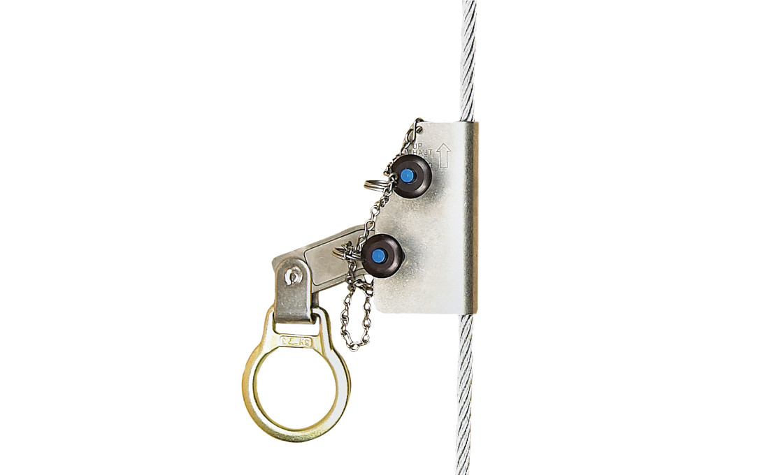
The SL-810S Fall Arrester slides smoothly along the wire rope of the WTF-83/10 Wire Rope Fall Protection System. It slides along the rope and engages automatically in the event of a fall.
Our corrosion- and abrasion-resistant Fall Arresters are suitable for deployment in harsh conditions, both on- and offshore. They can be attached and removed at any position on the rope and also feature an anti-inversion design, which prevents incorrect operation.

Re: Wire rope clips on suspension scaffolds; safety latches on large crane hooks; hanging scaffolds - order of assembly; jobsite fabricated lifting accessories - criteria; and horizontal lifelines: use of wire rope clips, anchorages, number of persons allowed to be connected, requirements relating to sag, and use of synthetic rope.
Question 1(a) - (c): When using horizontal lifelines as part of personal fall arrest systems, what type of wire rope clips does OSHA require, and how many clips must be used? Additionally, what are the horizontal spacing criteria for the uprights?
Subpart M does not specify what type of wire rope clip or how many clips/clamps must be used when installing a horizontal lifeline. However, under §1926.502(d)(8), these decisions must be made under the supervision of a qualified person when the system is designed. The determination of the horizontal spacing criteria for uprights is also left to the qualified person"s supervisory approval.1
In an August 28, 2000 letter to Mr. Troxell2, we addressed the related issue of using wire rope clips on a wire rope guardrail. In that letter, we cautioned that, as a practical matter, it is unlikely that the criteria requirements for guardrails under §1926.502(b) could be met unless the manufacturer"s recommendations for the number of clips to be used on wire ropes of different diameters were followed (for example, the Crosby Group, Inc., general catalog 2000 edition, has tables showing their recommendations for their clips). We also pointed out that OSHA"s standard for rigging equipment used for material handling, 29 CFR 1926.251, has a table showing the number of clips required for wire rope ½-inch and greater. We noted that although that standard does not apply to wire rope used for guardrails, when designing a rope system to meet the §1926.502 guardrail requirements, following the tables at §1926.251 will normally ensure that there will be enough clips.
Question 2: For a horizontal lifeline used as part of a personal fall arrest system during steel erection work, how tight should the lifeline be, and may synthetic rope be used for the horizontal lifeline?
With regard to the use of synthetic ropes, §1926.502(d)(14) specifies that, when using non-wire rope, synthetic rope (rather than nature fiber rope) must be used:
Question 5: Under §1926.451(d)(12)(v) and (vi), when wire rope clips are used on suspension scaffolds, "(v) U-bolt clips shall not be used at the point of suspension for any scaffold hoist," and "(vi) when U-bolt clips are used, the U-bolt shall be placed over the dead end of the rope, and the saddle shall be placed over the live end of the rope." Does §1926.451(d)(12)(v) contradict paragraph (d)(12)(vi)?
No. By its terms, §1926.451(d)(12)(v) prohibits the use of U-bolt clips at the point of suspension for any scaffold. The scaffold standard does not prohibit using U-bolt clips elsewhere. However, when using them elsewhere, under §1926.451(d)(12)(vi), the U-bolt must be placed over the dead end of the rope, and the saddle placed over the live end of the rope.
Question 6: Under §1926.251(c)(4)(iii), are eyes in wire rope bridles and slings or bull wires formed by wire rope clips permitted when used to lift scrap boxes or pendants?
This provision specifically prohibits eyes in wire rope bridles and slings or bull wires being formed by wire rope clips. There is no exception for lifting scrap boxes or pendants.
In our view, the industry recognizes that the following engineering factors, among others, must be considered when designing horizontal high-lines: the span and sag of the wire rope line, the weight of the load being lifted, the initial tension of the rope line, and the size of the columns.
Knotting wire rope compromises the integrity of the strength of the wire rope and is therefore prohibited. Based on the picture provided, which showed a knot in wire rope secured by a U-bolt clip, this practice would be in violation of §1926.251(c)(3).
In stricter senses, the term wire rope refers to a diameter larger than 9.5 mm (3⁄8 in), with smaller gauges designated cable or cords.wrought iron wires were used, but today steel is the main material used for wire ropes.
Historically, wire rope evolved from wrought iron chains, which had a record of mechanical failure. While flaws in chain links or solid steel bars can lead to catastrophic failure, flaws in the wires making up a steel cable are less critical as the other wires easily take up the load. While friction between the individual wires and strands causes wear over the life of the rope, it also helps to compensate for minor failures in the short run.
Wire ropes were developed starting with mining hoist applications in the 1830s. Wire ropes are used dynamically for lifting and hoisting in cranes and elevators, and for transmission of mechanical power. Wire rope is also used to transmit force in mechanisms, such as a Bowden cable or the control surfaces of an airplane connected to levers and pedals in the cockpit. Only aircraft cables have WSC (wire strand core). Also, aircraft cables are available in smaller diameters than wire rope. For example, aircraft cables are available in 1.2 mm (3⁄64 in) diameter while most wire ropes begin at a 6.4 mm (1⁄4 in) diameter.suspension bridges or as guy wires to support towers. An aerial tramway relies on wire rope to support and move cargo overhead.
Modern wire rope was invented by the German mining engineer Wilhelm Albert in the years between 1831 and 1834 for use in mining in the Harz Mountains in Clausthal, Lower Saxony, Germany.chains, such as had been used before.
Wilhelm Albert"s first ropes consisted of three strands consisting of four wires each. In 1840, Scotsman Robert Stirling Newall improved the process further.John A. Roebling, starting in 1841suspension bridge building. Roebling introduced a number of innovations in the design, materials and manufacture of wire rope. Ever with an ear to technology developments in mining and railroading, Josiah White and Erskine Hazard, principal ownersLehigh Coal & Navigation Company (LC&N Co.) — as they had with the first blast furnaces in the Lehigh Valley — built a Wire Rope factory in Mauch Chunk,Pennsylvania in 1848, which provided lift cables for the Ashley Planes project, then the back track planes of the Summit Hill & Mauch Chunk Railroad, improving its attractiveness as a premier tourism destination, and vastly improving the throughput of the coal capacity since return of cars dropped from nearly four hours to less than 20 minutes. The decades were witness to a burgeoning increase in deep shaft mining in both Europe and North America as surface mineral deposits were exhausted and miners had to chase layers along inclined layers. The era was early in railroad development and steam engines lacked sufficient tractive effort to climb steep slopes, so incline plane railways were common. This pushed development of cable hoists rapidly in the United States as surface deposits in the Anthracite Coal Region north and south dove deeper every year, and even the rich deposits in the Panther Creek Valley required LC&N Co. to drive their first shafts into lower slopes beginning Lansford and its Schuylkill County twin-town Coaldale.
The German engineering firm of Adolf Bleichert & Co. was founded in 1874 and began to build bicable aerial tramways for mining in the Ruhr Valley. With important patents, and dozens of working systems in Europe, Bleichert dominated the global industry, later licensing its designs and manufacturing techniques to Trenton Iron Works, New Jersey, USA which built systems across America. Adolf Bleichert & Co. went on to build hundreds of aerial tramways around the world: from Alaska to Argentina, Australia and Spitsbergen. The Bleichert company also built hundreds of aerial tramways for both the Imperial German Army and the Wehrmacht.
In the last half of the 19th century, wire rope systems were used as a means of transmitting mechanical powercable cars. Wire rope systems cost one-tenth as much and had lower friction losses than line shafts. Because of these advantages, wire rope systems were used to transmit power for a distance of a few miles or kilometers.
Steel wires for wire ropes are normally made of non-alloy carbon steel with a carbon content of 0.4 to 0.95%. The very high strength of the rope wires enables wire ropes to support large tensile forces and to run over sheaves with relatively small diameters.
In the mostly used parallel lay strands, the lay length of all the wire layers is equal and the wires of any two superimposed layers are parallel, resulting in linear contact. The wire of the outer layer is supported by two wires of the inner layer. These wires are neighbors along the whole length of the strand. Parallel lay strands are made in one operation. The endurance of wire ropes with this kind of strand is always much greater than of those (seldom used) with cross lay strands. Parallel lay strands with two wire layers have the construction Filler, Seale or Warrington.
In principle, spiral ropes are round strands as they have an assembly of layers of wires laid helically over a centre with at least one layer of wires being laid in the opposite direction to that of the outer layer. Spiral ropes can be dimensioned in such a way that they are non-rotating which means that under tension the rope torque is nearly zero. The open spiral rope consists only of round wires. The half-locked coil rope and the full-locked coil rope always have a centre made of round wires. The locked coil ropes have one or more outer layers of profile wires. They have the advantage that their construction prevents the penetration of dirt and water to a greater extent and it also protects them from loss of lubricant. In addition, they have one further very important advantage as the ends of a broken outer wire cannot leave the rope if it has the proper dimensions.
Stranded ropes are an assembly of several strands laid helically in one or more layers around a core. This core can be one of three types. The first is a fiber core, made up of synthetic material or natural fibers like sisal. Synthetic fibers are stronger and more uniform but cannot absorb much lubricant. Natural fibers can absorb up to 15% of their weight in lubricant and so protect the inner wires much better from corrosion than synthetic fibers do. Fiber cores are the most flexible and elastic, but have the downside of getting crushed easily. The second type, wire strand core, is made up of one additional strand of wire, and is typically used for suspension. The third type is independent wire rope core (IWRC), which is the most durable in all types of environments.ordinary lay rope if the lay direction of the wires in the outer strands is in the opposite direction to the lay of the outer strands themselves. If both the wires in the outer strands and the outer strands themselves have the same lay direction, the rope is called a lang lay rope (from Dutch langslag contrary to kruisslag,Regular lay means the individual wires were wrapped around the centers in one direction and the strands were wrapped around the core in the opposite direction.
Multi-strand ropes are all more or less resistant to rotation and have at least two layers of strands laid helically around a centre. The direction of the outer strands is opposite to that of the underlying strand layers. Ropes with three strand layers can be nearly non-rotating. Ropes with two strand layers are mostly only low-rotating.
Stationary ropes, stay ropes (spiral ropes, mostly full-locked) have to carry tensile forces and are therefore mainly loaded by static and fluctuating tensile stresses. Ropes used for suspension are often called cables.
Track ropes (full locked ropes) have to act as rails for the rollers of cabins or other loads in aerial ropeways and cable cranes. In contrast to running ropes, track ropes do not take on the curvature of the rollers. Under the roller force, a so-called free bending radius of the rope occurs. This radius increases (and the bending stresses decrease) with the tensile force and decreases with the roller force.
Wire rope slings (stranded ropes) are used to harness various kinds of goods. These slings are stressed by the tensile forces but first of all by bending stresses when bent over the more or less sharp edges of the goods.
Technical regulations apply to the design of rope drives for cranes, elevators, rope ways and mining installations. Factors that are considered in design include:
Donandt force (yielding tensile force for a given bending diameter ratio D/d) - strict limit. The nominal rope tensile force S must be smaller than the Donandt force SD1.
The wire ropes are stressed by fluctuating forces, by wear, by corrosion and in seldom cases by extreme forces. The rope life is finite and the safety is only ensured by inspection for the detection of wire breaks on a reference rope length, of cross-section loss, as well as other failures so that the wire rope can be replaced before a dangerous situation occurs. Installations should be designed to facilitate the inspection of the wire ropes.
Lifting installations for passenger transportation require that a combination of several methods should be used to prevent a car from plunging downwards. Elevators must have redundant bearing ropes and a safety gear. Ropeways and mine hoistings must be permanently supervised by a responsible manager and the rope must be inspected by a magnetic method capable of detecting inner wire breaks.
The end of a wire rope tends to fray readily, and cannot be easily connected to plant and equipment. There are different ways of securing the ends of wire ropes to prevent fraying. The common and useful type of end fitting for a wire rope is to turn the end back to form a loop. The loose end is then fixed back on the wire rope. Termination efficiencies vary from about 70% for a Flemish eye alone; to nearly 90% for a Flemish eye and splice; to 100% for potted ends and swagings.
When the wire rope is terminated with a loop, there is a risk that it will bend too tightly, especially when the loop is connected to a device that concentrates the load on a relatively small area. A thimble can be installed inside the loop to preserve the natural shape of the loop, and protect the cable from pinching and abrading on the inside of the loop. The use of thimbles in loops is industry best practice. The thimble prevents the load from coming into direct contact with the wires.
A wire rope clip, sometimes called a clamp, is used to fix the loose end of the loop back to the wire rope. It usually consists of a U-bolt, a forged saddle, and two nuts. The two layers of wire rope are placed in the U-bolt. The saddle is then fitted to the bolt over the ropes (the saddle includes two holes to fit to the U-bolt). The nuts secure the arrangement in place. Two or more clips are usually used to terminate a wire rope depending on the diameter. As many as eight may be needed for a 2 in (50.8 mm) diameter rope.
The mnemonic "never saddle a dead horse" means that when installing clips, the saddle portion of the assembly is placed on the load-bearing or "live" side, not on the non-load-bearing or "dead" side of the cable. This is to protect the live or stress-bearing end of the rope against crushing and abuse. The flat bearing seat and extended prongs of the body are designed to protect the rope and are always placed against the live end.
An eye splice may be used to terminate the loose end of a wire rope when forming a loop. The strands of the end of a wire rope are unwound a certain distance, then bent around so that the end of the unwrapped length forms an eye. The unwrapped strands are then plaited back into the wire rope, forming the loop, or an eye, called an eye splice.
A Flemish eye, or Dutch Splice, involves unwrapping three strands (the strands need to be next to each other, not alternates) of the wire and keeping them off to one side. The remaining strands are bent around, until the end of the wire meets the "V" where the unwrapping finished, to form the eye. The strands kept to one side are now re-wrapped by wrapping from the end of the wire back to the "V" of the eye. These strands are effectively rewrapped along the wire in the opposite direction to their original lay. When this type of rope splice is used specifically on wire rope, it is called a "Molly Hogan", and, by some, a "Dutch" eye instead of a "Flemish" eye.
Swaging is a method of wire rope termination that refers to the installation technique. The purpose of swaging wire rope fittings is to connect two wire rope ends together, or to otherwise terminate one end of wire rope to something else. A mechanical or hydraulic swager is used to compress and deform the fitting, creating a permanent connection. Threaded studs, ferrules, sockets, and sleeves are examples of different swaged terminations.
A wedge socket termination is useful when the fitting needs to be replaced frequently. For example, if the end of a wire rope is in a high-wear region, the rope may be periodically trimmed, requiring the termination hardware to be removed and reapplied. An example of this is on the ends of the drag ropes on a dragline. The end loop of the wire rope enters a tapered opening in the socket, wrapped around a separate component called the wedge. The arrangement is knocked in place, and load gradually eased onto the rope. As the load increases on the wire rope, the wedge become more secure, gripping the rope tighter.
Poured sockets are used to make a high strength, permanent termination; they are created by inserting the wire rope into the narrow end of a conical cavity which is oriented in-line with the intended direction of strain. The individual wires are splayed out inside the cone or "capel", and the cone is then filled with molten lead-antimony-tin (Pb80Sb15Sn5) solder or "white metal capping",zincpolyester resin compound.
Koetsier,Teun; Ceccarelli, Marc (2012). Explorations in the History of Machines and Mechanisms. Springer Publishing. p. 388. ISBN 9789400741324. Archived from the original on 31 March 2017. Retrieved 9 April 2014.
Donald Sayenga. "Modern History of Wire Rope". History of the Atlantic Cable & Submarine Telegraphy (atlantic-cable.com). Archived from the original on 3 February 2014. Retrieved 9 April 2014.

Cable Lock 8119DPF is a combination lock with a 5 foot long cable made of vinyl coated, braided steel wire. It operates by rotating four numerical dials and allows for easy locking and handling with keyless convenience. It can be used to secure a variety of items, such as power equipment, ladders, trailers, tool boxes, bicycles and sports equipment. The width of the body measures 4.7 cm.
Cable Lock 8154DPF is a keyed lock with a 6 foot long cable made of vinyl coated, braided steel wire. It is imported with two keys that are connected with a metal split ring. The 5 pin cylinder locking mechanism offers maximum pick resistance. It can be used to secure a variety of items including toolboxes, ladders, gates, generators, hand trucks, bicycles, skateboards and sports equipment. The width of the body measures under 3.8 cm.

They are heavy duty, precision machined gripping devices which are designed to grip wire rope from light loads to ultimate breaking loads. They are designed for use when light, compact grip is desired and where conductor damage is not a factor. They work on any lay wire rope. These grips will hold regardless if the wire is greased, dirty, wet, tarred, plated, etc. Each grip comes with a wide range of adapters and liners to grip different size wire rope.
Pull wire and cable while maintaining tension until the line can be permanently anchored. Use with stranded bare steel wire and cable in applications where marring can be tolerated. Clamps with spring-loaded jaws grip the cable before tensioning to aid proper positioning. The clamp with latch provides a more secure grip that prevents wire and cable from slipping out of the jaws. Warning: Do not use as an anchor.
Pull the trigger by one hand and the wire rope grip will be opened easily and release instantly to quickly insert or remove wire. Specially designed for gripping a wide range of cables.
Wire Rope Grips are manufactured from drop-forged, heat-treated steel for excellent durability, They are forged of alloy steel with heat treatment, Forged alloy steel construction is durable yet lightweight. The rack has strong anti-tension with high occlusion strength. They are not easy to slide and deformation, yellow chromate finish protects grips from rust and corrosion.
Attach these clamps by running a wire rope through the jaws to create an attachment point anywhere along the wire rope. The eye is often used with a ratchet puller.
It is also called cable grip, wire rope pulling grip, also known as "pork chops" due to their shape which are used for getting a "bite" on wire rope in the middle of the line. They work great for tensioning projects like zip lines, bracing cables and utility lines, just to name a few. They are typically connected to some kind of mechanical pulling unit, whether it"s a cable comealong or a lever chain hoist. These types of pullers help you to achieve serious leverage and tension cable to your desired specification
This cable grip tool grip is used in various applications including general use in wire rope distributor warehouses, in the field with construction crews, in the field with construction crews, in mines-coal-silver-copper (used in conjunction with mining conveyors), and anywhere wire rope is used. Widely to be used in the power, communications, and general construction fields to pull wire and cable.
Aluminum Alloy Wire Grip For Conductor Automatic Come Along Clamp is suitable to tighten the Insulated conductors or adjust of sag. With high stength aluminum titanium alloy forging, the weight is light. The jaw part adopts a special texture processing so that It can firmly clamp the cable and does not hurt the inner core whether winter or summer. Aluminum Alloy Wire Grip For Conductor Automatic Come Along Clamp is used to adjust sag in the operation of erecting wire and sagging.
Unlike traditional cable grips, these grips were designed to work easily with just one hand. The "trigger" design of these grips allows for total dexterity and easy manipulation so the wire rope pulling grip can be opened and installed on the line in just a matter of seconds, using only one hand. Heavy-duty design ensures these grips will hold up out in the field.
One-handed operation thanks to "trigger" design--simply pull on trigger with one hand and the wire rope pulling grip will open easily and release instantly
There are a number of tools and methods for tensioning high tensile wire. One method uses a cable puller (come-along) in combination with a tool such as this high-quality china made wire puller. The high tensile wire is placed in the jaw of the Grip. When used properly, the grip"s smooth, V-groove jaw will not damage galvanized coating on wire.
Lightweight, especially economical grip Designed for working with solid and stranded bare wire from .08" (2 mm) to .20" (5.1 mm) Single "V" groove jaw Made in china, All models are fitted with swing down safety latch as standard.
WARNING: Before each use, clean jaw area and inspect grip for proper operation to avoid slippage. When used on/near energized lines, ground, insulate, or isolate grip before pulling. Do not exceed rated capacity. Always match proper size and type of grip to application. Wire Rope Grips are to be used for temporary installation, not for permanent anchorage.


 8613371530291