
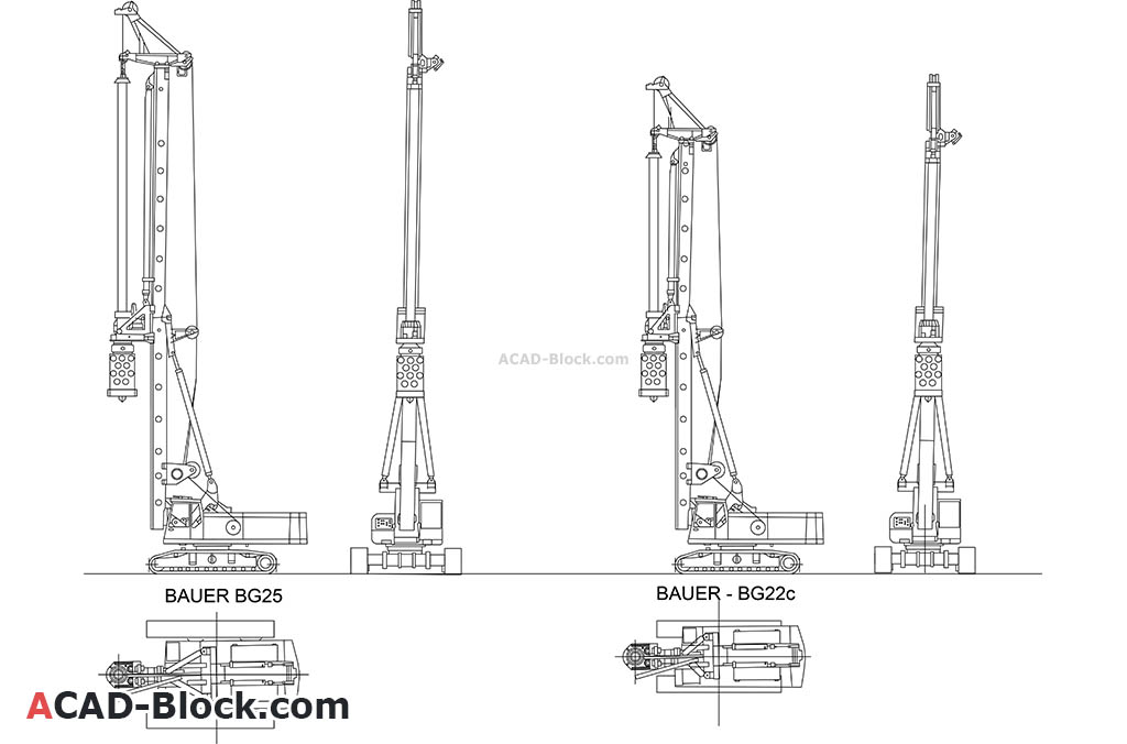
workover rig drawing free sample
Download Workover & Drilling Rig Inspection Checklist As we mentioned in the Rig Audit Article, rig inspection is an important process that shall be done from time to time. Especially, after the rig moving to a new drilling location.

This website is using a security service to protect itself from online attacks. The action you just performed triggered the security solution. There are several actions that could trigger this block including submitting a certain word or phrase, a SQL command or malformed data.
The grey steel girders of Platform Holly rise 235ft (72m) above the waters of the Pacific Ocean, just a couple of miles off the Santa Barbara coast. Above the water, this decommissioned oil rig is dull and lifeless, but the view below the surface is very different. Beneath the waves, colourful fish, crabs, starfish and mussels congregate on the huge steel pylons, which stretch for more than 400ft (120m) to the ocean floor.
The big question is what to do with these enormous structures when the fossil fuels stop flowing. With curbing climate change rising up the international agenda, and with some questioning whether we have already passed peak oil, hastened by the coronavirus pandemic, the number of defunct rigs in the ocean is set to get bigger. Removing them from the water is incredibly expensive and labour-intensive. Allowing them to rust and fall into disrepair is an environmental risk that could seriously damage marine ecosystems.
For some species, offshore rigs are even better nurseries than natural reefs. The towering pylons are the perfect spawning grounds for tiny fish larvae
But there is one way in which these old rigs can be remarkably useful: the subsurface rig provides the ideal skeleton for coral reefs. Teeming with fish and other wildlife, offshore rigs like Platform Holly are in fact the most bountiful human-made marine habitats in the world.
The practice of transforming rigs into reefs in the United States dates back almost 40 years. In 1984, the US Congress signed the National Fishing Enhancement Act which recognised the benefits artificial reefs provided and encouraged states to draw up plans to turn defunct rigs into reefs. The five coastal states on the Gulf of Mexico – Alabama, Florida, Louisiana, Mississippi and Texas – all have rigs-to-reefs programmes and have converted more than 500 oil and gas platforms into artificial reefs.
Marine scientists Emily Hazelwood and Amber Sparks are on a mission to replicate this conservation success in other parts of the world. They founded the California-based organisation Blue Latitudes in 2014 to raise awareness about the benefits of rigs and persuade oil companies and governments to designate them as permanent reefs.
Offshore rigs are among the most productive fish habitats in the world, according to marine biologist Milton Love who has spent 20 years studying fish populations around oil and gas platforms in California. They provide marine wildlife with food, shelter from predators and a safe breeding ground.
For some species, the rigs are even better nurseries than natural reefs, says Love. The towering pylons are the perfect spawning grounds for tiny fish larvae. "A lot of them are just drifting," says Love. "They want to settle." The 500ft (150m) high underwater structures provide an opportunity for just that.
One of the big beneficiaries is rockfish, stocks of which have been heavily depleted due to overfishing along the US West Coast. These fish are found in abundance around oil platforms. For instance, the platforms have helped revive the critically endangered bocaccio rockfish. "We"ve found a very high density of young bocaccio at platforms, around 400,000 at six platforms. We didn"t see that at natural reefs," says Love, adding that the number of juvenile bocaccio found at rigs was enough to boost the adult stock of the Pacific Coast population by around 3%.
The abundant fish populations found at Californian platforms can partly be attributed to the fact that oil rigs serve as de facto marine protected areas, says Love. In California, fishing around oil and gas platforms is prohibited.
For one study, Lowe attached sensors to fish living by three oil platforms, before moving them to a natural reef located up to 18km (11 miles) away and monitoring their movements over two years. A quarter of the fish, across all species, quickly returned to their home oil platform, while others would migrate back during non-breeding seasons. "They had a higher likelihood of going back to their original platform than somewhere else. They really like their home platform. This showed us a lot about how the fish treat the platform as a habitat," says Lowe.
One reason for this affinity is that the rigs offer a property rarely found in featureless open water: their considerable height. The platform acts as a pinnacle and allows fish to move into deeper water as they mature, without having to leave their habitat, according to Lowe. Typically, fish living in shallow reefs will leave their habitat when they are fully grown and venture out to open sea. The fish found on oil rigs simply have to move down the platform, without ever venturing far from their refuge.
Many scientists are calling for Californian platforms to be preserved as artificial reefs, given the bountiful ecosystems they harbour. The state introduced a law in 2010 allowing for rigs to be converted in reefs, but to date no platforms have been reefed. That could change in the next decade; eight of the state"s 27 rigs are no longer operating and several will be decommissioned in the next few years.
Blue Latitudes" Sparks says it is a challenge convincing Californians, "the greenest folks you"ll meet", of the merits of keeping rigs in the ocean. California is the US state with the most ambitious climate goals. By 2030 the state aims to slash emissions by 40% compared with 1990 levels and has passed a law that all electricity must come from carbon-free sources by 2045.
While marine life might benefit from the subsurface structures, there are concerns about the rigs-to-reefs programmes also supporting extractive industries (Credit: Alamy)
It"s not hard to see why some are reluctant. The extraction and burning of fossil fuels including oil and gas are major drivers of climate change. Overall, in 2019, gas made up 21% and oil 34% of the world’s CO2 emissions from fuel, with a significant proportion coming from offshore rigs like these and thousands of others.
But the objections are not just symbolic. There are concerns that the cost savings offered to oil companies under the rigs-to-reefs programme could encourage them to expand, Hislop notes. She adds that research and discussions about what to do with the rigs once they have been decommissioned are ongoing.
But Blue Latitudes says the aim of rigs to reefs is not to reward polluters and boost the oil industry, but to protect valuable marine habitats by offering an alternative to complete platform removal.
If California"s platforms are toppled, it would result in the loss of 27 huge marine ecosystems. Some of these rigs are taller than the Eiffel Tower – the Harmony platform in the Santa Barbara Channel, for example, reaches depths of 1198ft (365m). "California platforms are some of the largest and deepest in the world," says Hazelwood. "You don"t even see the beams, they are so encrusted with marine wildlife."
![]()
Drill floor (#21) is the area on the rig where the tools are located to make the connections of the drill pipe, bottom hole assembly, tools and bit. It is considered the main area where work is performed.
Setback (#17) is a part of the drill floor (#21) where the stands of drill pipe are stood upright. It is typically made of a metal frame structure with large wooden beams situated within it. The wood helps to protect the end of the drill pipe.
Stand (#16) is a section of 2 or 3 joints of drill pipe connected and stood upright in the derrick. When they are pulled out of the hole, instead of laying down each joint of drill pipe, 2 or 3 joints are left connected and stood in the derrick to save time.

SCOPE: To provide a representative basis for determining the availability, capability, dependability, reliability of Stability Systems on Land Based Work-Over Rigs and the recommended practices and procedures for their safe use.
The rig location area may grade away from the well bore along centerline II at a maximum drop of 1:20. The cross grades, parallel to centerline I, should be level. The area shall provide a minimum bearing capacity of 6000 psf.
The following drawings and charts (extracted from Wyoming OSH Regulations) with supporting explanation are intended to assist you in understanding the "WYGUY" system and its implementation.
Using the chart: An anchor in Zone "A" located a horizontal distance of 70 feet from the "Well Head" would require an anchor of what minimum holding capacity? On the chart move along the horizontal legend from left to right until you reach 70 feet. At this juncture proceed vertical until you intersect the curved line for Zone "A", now follow the intersecting horizontal line, left toward the vertical legend. We have now determined that the minimum holding capacity for the anchor, at this precise location, is 20,000 pounds.
Standing at the "Well Head", with the well bore immediately to your back, proceed North (in direction monkey board is facing) 24 paces. (The pace length is not as important as the numerical relationship of the units and the consistency of the unit length. The method will work with any unit of length as long as the same unit is used throughout.) Place a stake or other marker at this location (Bench Reference). Turn West 90 degrees and proceed forward 10 paces. At this location turn your body so that the front portion of your anatomy is approximately parallel to the radial of the guy anchor. If the northwest guy anchor is forward of your right shoulder and the southeast guy anchor is aft to the rear of your left shoulder, it can then be presumed that the radial angles are within acceptable parameters. Repeat the procedure from the bench reference, this time to the east, proceed ten paces. In this orientation the northeast anchor should be forward of the left shoulder and the southwest anchor should be aft of the right shoulder.
A survey of 13 drilling contractors operation 193 drilling rigs in northern Canada and Alaska indicated that there is a wide range of experience and operating practices under extremely low temperature conditions. While there is very little precise information available, there have been a sizeable number of failures in portable masts while in the lowering or raising process in winter. Thus the exposure to low temperature failures focuses on mast lowering and raising operations. Based on reports, however, this operation has been accomplished successfully in temperatures as low as -50 degrees F. While the risk may be considerably greater because of the change in physical characteristics of steel at low temperatures, operators may carry on "normal" operations even at extremely low temperatures. This may be accomplished by a program of closely controlled inspection procedures and careful handling and operation. This should reduce damage and impact loading during raising and lowering operations. At the present, there seems to be no widely accepted or soundly supported basis for establishing a critical temperature for limiting the use of these oilfield structures. Experience in the operation of trucks and other heavy equipment exposed to impact forces indicates that -40 degrees F may be the threshold of the temperature range at which the risk of structural failure may increase rapidly. Precautionary measures should be more rigidly practiced at this point. The following recommended practices are included for reference:
If maintained to these tolerances the sags will indicate a pretension of 1000 pounds for crown to ground guywires and 500 pounds for tubing board guywires. this is based on the use of 5/8 inch, 6x19, or 6x37 class, regular lay, ips, IWRC wire rope, installed according to the rigging guidelines set forth in chart depicted in Figure 5-5
The drawing on the following page, Figure 5-4, (SAME AS FIGURE 4-4) is another illustration of the continuing evolution of Rig Stability System engineering and design. It represents the latest API thinking relative to planing and preparing a Rig Stability System.
CAUTION: SOLE EMPHASIS SHOULD NOT BE PLACED ON PULL TESTING OR ALTERNATIVES TO PULL TESTING AS THIS MEASURES ONLY ONE COMPONENT OF THE RIG STABILITY SYSTEM.
The rig contractor should be responsible for the following: a. Insuring that anchor capacities are verified and that anchor spacing and capacity is suitable for the mast guying pattern and anticipated loading.
b. Records of pull testing or records of other methods used to verify temporary anchor capacity should be retained by the rig contractor until the job is complete and the guy wires have been removed from the anchors. The records should indicate the capacity of each anchor, the date of verification, name and phone number of the party responsible for verification, and the soil condition at the time of verification.
OUT OF AN ABUNDANCE OF CAUTION IT IS EXTREMELY IMPORTANT TO POINT OUT THAT THE PREVENTION OF RIG UPSET IS DIRECTLY DEPENDENT ON THE TOTAL INTEGRITY OF THE RIG STABILIZATION SYSTEM. THE SYSTEM INCLUDES ALL OF ITS COMPONENTS AND IS ONLY AS SOUND AS ITS WEAKEST MEMBER.
Our research has concluded, that the latest State-of-the-Art in RIG STABILIZATION is to be found in the pending American Petroleum Institute, Recommended Practice for MAINTENANCE and USE of DRILLING and WELL SERVICING STRUCTURES.

This website is using a security service to protect itself from online attacks. The action you just performed triggered the security solution. There are several actions that could trigger this block including submitting a certain word or phrase, a SQL command or malformed data.
The claimed invention relates generally to well drilling and servicing equipment, and more specifically to portable rigs for handling pipe strings when making up and disconnecting long strings of pipe used in a bore hole during operations that are carried out in the exploration and production of petroleum and other fluids and minerals from substantial depths below the earth"s surface.
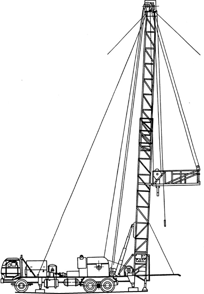
When such service operations become necessary, a portable installation called a workover rig is brought to the well site and set up. Generally, these rigs consist of a derrick or mast which supports pulleys or block and tackle arrangements that are operable to pull the pipe string from the well. These prior art workover rigs are usually heavy and difficult to erect and further often have the limited operational capability of only being able to hoist or pull pipe from a well without the capability of snubbing or pushing pipe back into the well. Since these conventional workover rigs cannot develop a downward force to push a string of pipe into the well, in such operations the well must necessarily always be under control or "dead", as is known in the art. This may require a preparatory operation of injecting a suitable substance such as mud or "kill" fluid into the well to maintain sufficient column weight of fluid to resist the pressure within the well which is tending to force the tubing out. However, it is usually desirable to carry out the workover operations without resorting to the injection of "kill" fluid into the well since the well may be lost if the formation is damaged because of the presence of the workover "kill" fluid. In such "killing" workover operations, there is a very high risk that the productivity of the subsurface formation may decline so severely after killing the well that the well must be abandoned.
An overriding concern in the construction of workover rigs is to get the necessary equipment into and out of the well as rapidly and safely as is economically possible. This concern has led to the development of a portable well service rig having a transportable mast or derrick. Before the invention of the first portable well service unit, it was necessary to leave the drilling derrick in place over the well for use in future well service operations. The portable well service rig eliminated the need for a permanent derrick and thus materially reduced overall well service costs. The early portable rigs, however, were unloaded in a heap and later sorted out, and then assembled without any definite plans therefore consuming a substantial amount of time in rigging up. Even when unitized and transported on pallets, a significant amount of time was required for transporting, rigging up and dismantling the palletized equipment. In the palletized approach, the field assembly and erection of the mast, mast support structure and reeving of the hoist cable caused expensive but unavoidable delays. Therefore recent improvements to conventional portable workover rigs have focused on changes which simplify the operations of transporting, rigging up and dismantling.
One of the problems associated with the development of the portable workover rig is that of providing sufficient working space below the mast floor while limiting the mast and its supporting base to dimensions which permit its transportation across public highways. A working space must be provided below the mast floor in order that the mast can be supported vertically above and engage well head equipment which may extend as much as eight to ten feet above the elevation of the rig platform deck. The minimum height of the mast is determined primarily by the length of the sections of pipe string added to or removed from the pipe already in the well bore. However, if the mast is so high that its length and height clearance when in a horizontal position on the workover rig exceeds the limits allowed by the state, the mast must be at least partially disassembled or must be telescoped. Most wells have tubing sections which are in the range of thirty-six to forty feet long, so that the construction of a transportable mast assembly having a stroke for accomodating the removal or insertion of such tubing sections poses no problem insofar as complying with state highway regulations.
As mentioned above, the conventional practice has been to provide a mast having telescoping sections or having sections which must be separately assembled and erected on site. To provide ample clearance for the well head equipment, the mast floor has been elevated above the ground level by placing it on a mast substructure carried by the rig base platform. This substructure is normally fabricated of heavy structural steel in a massive weldment which must be separately transported. The loads it must bear are greater than those born by the mast, since the substructure must support not only the weight of the derrick with its pipe string load, but other loads, such as the rotary table and draw works as well. However, the length and height of the separate mast support base when combined with the reclining mast may in some cases exceed highway limits, so that separate transportation, field assembly and erection are required. Most conventional rigs provide separate support base and mast sections which may be unbolted and separately transported to provide the short lengths allowed for highway travel. However, additional rigging up and tear down time is required for such arrangements.
Other important considerations involved in the construction of portable workover rigs are the strength and stability of the mast. The mast must be constructed to safely carry all loads which will ever be used in the well over which it is placed. This is the collapse resistance caused by vertical loading, or the dead load capacity of the mast. The largest dead load which will be imposed on the derrick will normally be the heaviest string of production tubing run in the well. However, this heaviest string of tubing will not be the greatest strain placed on the mast. The maximum vertical load which will ever be imposed on the mast will probably be the result of pulling on equipment, such as drill pipe or casing, that has become stuck in the hole. Therefore it must be considered that, sometime during the useful life of the mast, severe vertical strain will be placed on it because the equipment has become stuck in the hole. Therefore the mast and its intermediate support platform must be constructed to withstand and react loads which will exceed the capacity of the hoist line which will be used on the rig.
The mast must be also designed to withstand the maximum wind loads to which it will be subjected. The horizontal force of the wind acting on the mast and production tubing is usually counteracted by using from one to three guy wires along each leg of the mast which are attached to "dead man" anchors located some distance from the mast. A "dead man" anchor is made from a short length of large pipe, a concrete block, or a short section of timber, which is buried in the ground to provide an anchor for the guy wire. A substantial amount of time and labor is expended in setting up the "dead man" support lines. Additionally, when carrying out workover operations off shore, there is no practical way to anchor the guy lines. A suitable structural alternative for the guy wire supports is necessary for reacting the wind loads, and the snubbing forces must also be reacted in order to drive production tubing into an offshore well against the downhole pressures which may be encountered. Therefore there is a continuing interest in improving the design of support substructure for free-standing masts which do not require guy wires for support.
As a result of the many improvements to portable workover rigs, such vehicles now transport practically all the necessary servicing equipment directly to the field locations and when servicing has been completed, remove the necessary equipment to another well in need of service in the same field or in a different field miles away. Thus the equipment necessary to service a number of wells each having different service requirements has been greatly reduced, and consequently the labor and cost, as well as the amount of equipment has correspondingly dropped. However, there still remains considerable interest in the provision of more efficient and simplified machines in order that the job of well servicing in general may be carried out efficiently and at reasonable cost.
It is, therefore, the principal object of the present invention to provide an improved general purpose workover rig having a unitized configuration which is transportable across public highways and which can be easily rigged up and dismantled in the field.
Still another object of the invention is the provision of a workover rig having a mast, a mast support substructure, and draw works in which the static load of the draw works is supported by a portable base platform member rather than by being supported by the intermediate mast support substructure.
Yet another object of the invention is the provision of a workover rig having draw works carried by a portable platform and a mast and mast support substructure which are separately movable from a reclining transport position to an erect operating position wherein erection and retraction of the mast and mast support assembly can be carried out without disturbing cable reeving on the mast or on the draw works.
An important object of the present invention is the provision of draw works for a workover rig which can be carried in a reclining position on a portable rig platform and which is operably connected to develop driving forces required for either hoisting or snubbing operations.
Still another object of the invention is the provision of a portable workover rig having a mast and mast support substructure which are separately movable from a reclining transport position over a portable base platform to an erect workover position overlying well head equipment lying either above or below the elevation of the portable base platform.
Yet another object of the invention is the provision of a base support substructure for an erectable mast and a carriage assembly for moving the base support substructure from a reclining transport position over a portable base platform to an erect workover position, the carriage assembly cooperatively coupled to the base platform for stabilizing the erectable mast in free-standing relation on the mast support substructure and for transmitting mast load reaction forces through the portable base platform.
Another object of the invention is the provision of a workover rig having an erectable mast supported on a cantilever support substructure which is movable from a reclining transport position overlying a portable base platform to an elevated position of use wherein the cantilever support base is extended beyond the portable base platform for carrying out workover operations.
The foregoing objects are achieved by a workover rig which is mounted on a portable base platform such as a skid or the bed of a trailer vehicle, and which features a collapsible mast assembly which is movable from a reclining transport position to an erect elevated position of use. The mast assembly is supported for freestanding operation by a carriage assembly including a cantilever substructure support base mounted on the rig support platform for pivotable movement from the reclining transport position to an elevated position of use. The carriage assembly includes lift arms coupled in parallel relation intermediate the cantilever support structure and the rig support platform, thereby defining a parallelogram throughout the range of movement of the mast support assembly for maintaining the cantilever support base in parallel alignment with the base platform. According to this arrangement, the mast and the carriage assembly are separately collapsible for transport in a low profile, reclining position over the base platform to comply with the length and height limitations established for public highways. The mast and the carriage assembly are separately erectable to an elevated operating position overlying well head equipment which may be disposed at an elevation either above or below the elevation of the portable base platform. The mast is connected in hinged engagement with the carriage assembly, and both the carriage assembly and the mast are separately driven from the transport position to the erect operating position by linear hydraulic actuators. The linear hydraulic actuators in combination with the carriage assembly serve to stabilize the mast for free-standing operation and transmit mast load reaction forces through the portable base platform. An important feature of this arrangement is the cantilever support substructure which is extended to an elevated operating position beyond the portable base platform for carrying out workover operations adjacent elevated well head equipment. A further advantage of this arrangement is that the mast, mast support substructure, and draw works can be carried in a collapsed, low profile transport position and both erection and retraction of the mast and mast support assembly can be carried out without disturbing the cable reeving on the mast and draw works.
According to an important aspect of the invention, the workover rig is provided with a mast, a mast support substructure, and draw works in which the static load of the draw works is supported by a portable base platform member rather than being supported by the intermediate mast support substructure. In this arrangement, the draw works includes a linear hydraulic actuator having rod and housing elements in which one of the elements is anchored to the base platform with the other element being mounted for movement along the base platform through a stroke pathway which extends transversely with respect to the mast. The traveling sheaves are cooperatively reeved with hoist and snub cables for developing driving forces required for either hoisting or snubbing operations. The advantage of this arrangement is that the intermediate mast support substructure must support only the mast in an erect operating position with the substantial weight of the draw works being supported by the portable base platform. This arrangement permits the mast support substructure to be easily movable from the reclining, low profile transport position to the elevated workover position without the burden of the draw works. Hoisting and snubbing operations are carried out by the draw works which includes a linear hydraulic actuator carried on the base platform, a load engaging traveling block supported for vertical movement along the mast by hoist and snub cables, and by traveling sheaves carried by the actuator through a stroke pathway which is oriented transversely with respect to the mast. In this arrangement the load engaging traveling block is driven upwardly or downwardly along the mast in response to extension and retraction of the rod and housing elements of the hydraulic actuator.
In yet another important embodiment of the invention, a vertically adjustable stack assembly is provided for accomodating the existing elevation of well head flange connections. The vertically adjustable stack assembly includes an adjustable support column assembly anchoring the rig platform to the well head casing, and an adjustable support column assembly interposed between the well head casing and the mast for transferring the weight of the mast from the intermediate mast support structure to the well casing. The vertically adjustable stack assembly simultaneously anchors the portable base platform to the well head casing, thereby stabilizing the mast support substructure, while relieving the burden of the mast from the intermediate mast support substructure. This arrangement helps stabilize the mast for free-standing operation on the mast support substructure and for transmitting mast load reaction forces through the portable base platform, thereby eliminating the need of dead man anchor lines which would otherwise be required for stabilizing the mast and for reacting dynamic mast loads.
Finally, the portable workover rig of the invention is adapted to perform drilling operations by the combination of a vertically yieldable stab assembly which interconnects a powered drill sub with a traveling block for permitting vertical displacement of the powered drill sub during make-up and break-out operations while simultaneously reacting torque forces which arise in response to rotary forces applied to the drill string. The vertically yieldable stab assembly includes upstanding stab receptacles anchored to the top side of the traveling block and stab elements downwardly depending from the under side of the powered drill assembly for engagement with the stab receptacles. Each stab element is supported for vertical reciprocal movement between retracted and extended positions, and each stab element is yieldably biased to the fully extended position, thereby permitting vertical displacement of the power sub relative to the traveling block during the make-up and break-out operations while reacting torque forces which are produced by operation of the powered drill sub.
The foregoing and other related objects and advantages of the present invention will become more apparent from the following specification, claims and appended drawings wherein:
FIG. 3 is a top plan view of the workover rig of FIG. 1 with the mast and carriage assembly removed which illustrates the layout of the draw works and related equipment on the deck of a portable rig support platform;
FIG. 7 is a side elevational view of a skid mounted workover rig having draw works and an erectable mast constructed according to the teachings of the present invention;
FIG. 10 is a perspective view which illustrates the arrangement of sheaves and reeving of cables for conducting snubbing operations on the workover rig shown in FIG. 1;
FIG. 11 is a perspective view which illustrates the arrangement of sheaves and reeving of cables for conducting hoist operations on the workover rig shown in FIG. 1;
FIG. 16 is a front elevation view of the completed vertically adjustable stack assembly shown interconnecting the mast support substructure and the rig support platform with the flanged connector of a well head assembly;
In the description which follows, like parts are marked throughout the specification and drawings with the same reference numerals, respectively. The figures are not necessarily drawn to scale and in some instances portions have been exaggerated in order to more clearly depict certain features of the invention.
Referring now to the drawings, and more particularly to FIGS. 1-4, a workover rig 10 is shown having a transportable mast assembly 12 and draw works 14 supported on a portable trailer platform 16. The trailer platform 16 includes the usual longitudinal side frame rails 18, 20 which supports forward and rear decks 22, 24, respectively. The side rails 18, 20 are interconnected by the usual structural members, including a tailboard 26. The trailer platform 16 includes a fifth wheel connection 28 for attachment to a tractor, and rear wheels 30 supported by shock assemblies and leaf springs in the usual manner. Outrigger jacks or props 32 support the side frame rails 18, 20 to prevent tilting or overturning of the rig during operation and also for maintaining the orientation of the trailer platform 16 once it has been set up. The jacks 32 are preferably hydraulically actuated and are controlled from a central station so that the trailer platform 16 can be aligned in parallel with the ground or inclined in a tilted position for workover of slant wells. Each jack 32 is equipped with a stabilizer pad 34 for engaging a mud sill (not shown) so that the trailer load can be more evenly distributed. Slung underneath the side frame rails 18, 20 are tool boxes 36 and a spare tire 38. Anchored top side on the forward deck 22 is power unit 40 which develops the main hydraulic power for the draw works 14 and includes hydraulic pumps driven by a diesel engine. The power unit is coupled to a hydraulic reservoir 42 so that as the required pressure in the system exceeds predetermined levels, one or another pump automatically unloads into the reservoir 42 and all engine horse power is then diverted for driving the alternate pump(s). Immediately forward of the power unit 40 are a pair of fuel tanks 44, and overlying the fifth wheel connection 28 is a hose basket 46. Overlying the fuel tanks is an upstanding stop bar 47 for engaging the mast assembly and supporting it in spaced relation with the forward deck overlying the power unit and fuel tanks when the transportable mast assembly 12 is disposed in its reclining transport position, as illustrated in FIGS. 1 and 2. Also anchored to the trailer platform 16 intermediate the forward and rear decks is a guide tube 48 which is straddled by the hydraulic reservoir 42 for receiving the movable actuator element of the draw works 14 as will be discussed in greater detail below.
Referring again to FIGS. 1-4, the transportable mast assembly 12 comprises generally an elongated mast 50 pivotally mounted on a mast support substructure 52 which is in turn pivotally mounted on a mast carriage assembly 54 which is mounted for pivotal movement from a transport position shown in FIG. 2 to an elevated position of use shown in FIG. 1. The mast 50 is formed by two upstanding mast sections 50A, 50B which are laterally spaced to define a vertical load transport zone 56 through which a traveling block 58 is transported during pipe running operations. The upper ends of the mast sections 50A, 50B are structurally interconnected by a crown block 60 which improves the mechanical stability of the mast and which also serves to support crown block sheaves in a manner to be disclosed hereinafter. Each mast section 50A, 50B is defined by four leg members 62A, 62B, 62C and 62D, and 64A-D, respectively. The leg members are generally arranged at the corners of a square with the forward leg portions terminating in a clevis which receives a hinge pin 66 which pivotally secures the forward legs to the mast support substructure 52. Each mast section 50A, 50B is provided with girt members 68 and brace members 70 which are structurally interconnected with the leg members to insure rigidity of each mast section. A clevis 72 is anchored on opposite sides of the mast support substructure 52 for anchoring the rear legs 62B, 64B of the mast when it has been erected to the upright position.
Erection of the mast 50 to the upstanding, elevated workover position is preferably carried out by rotating the mast support substructure 52 from its reclining transport position to its fully extended upright position while the mast 50 remains in its reclining position. After the mast support substructure has been fully stabilized in the upright position, the hydraulic lift cylinders 80 are actuated to cause the mast 50 to be pivoted to its upright standing position on the cantilever support base 74. The hydraulic lift cylinders 78, 80 are continuously pressurized in order to further stabilize the mast support substructure and transmit mast loads to the trailer platform 16. Retraction of the mast 50 is carried out in the reverse order by first uncoupling the rear leg portions at the clevis 72 and retracting the double acting hydraulic lift cylinders 80 until the mast 50 is substantially horizontal. Thereafter, the hydraulic lift cylinders 78 are retracted until the mast support substructure is resting in its reclining transport position with the upper end of the mast resting on the tie-down bar 47.
The traveling block 58 is guided for vertical displacement along the rear legs 62A, 64D, which serve as guides, as can best be seen in FIGS. 4 and 23. The traveling block 58 includes a main cross member 98 which extends horizontally between the legs 62D, 64D and is provided with guide rollers 100 rotatably mounted about shafts 102 at either end of the frame. The periphery of each roller is concave to conform to the shape of the tubular members 62D, 64D and vertically guide the traveling block as it is reciprocated along the mast 50. A rotary table 104 is carried by the main cross member 98 of the traveling block to facilitate workover or drilling operations.
Referring to FIGS. 3, 4, 10, 11 and 19-21, the linear hydraulic actuator 92 is carried on the rear deck 24 of the trailer platform 16 and includes rod and cylinder housing elements 128 and 130, respectively. The rod element 128 is rigidly attached at one end to an anchor weldment 132 whereby the actuator assembly 92 is supported in spaced, parallel relation with the rear deck 24 so that the cylinder housing 130 can move freely in extension and retraction. Reciprocal movement of the cylinder 130 is stabilized by the guide tube 48 which receives the freely projecting end of the cylinder housing 130. The anchor weldment 132 includes a socket for engaging a threaded shaft portion 134 of the rod element 128.
Extension and retraction of the cylinder housing 130 is controlled from the operator platform 126 which is horizontally supported from the aft legs of the mast at an elevation convenient for workover operations. The forward part of the platform (not shown) houses hydraulic valves that control the actuation of the various components as will be explained.
Referring now to FIG. 16, the workover rig 10 is set up adjacent a well site in which a well casing 230 is terminated by a lower well head flange 232 and is anchored by a concrete block 234 in the usual manner. As is conventional, a blow out preventer 236 is located above and connected to the lower well head flange 232. A slip 238 is located above and connected to the blow out preventer 236. Located above and connected to the slip is an energizable packer 240. The packer is coupled to an upper well head flange 242 disposed at an elevation above the trailer platform as indicated by the elevation reference line 244. The BOP slip and packer are all concentrically aligned with the well casing 230 so that a tubing string may be moved upwardly through the well casing along the bore axis 248 as the tubing string is run out of the well. Conversely, when running the tubing string 246 into the well, each section is moved downwardly through the packer, slip and blow out preventer into the well casing 230.
The blow out preventer 236 may be of any suitable type, but is preferably hydraulically energizable for engaging the tubing string 246 in a fluid sealing relation to prevent the well from blowing out. The slip 238 may also be of any suitable construction and is preferably double acting, i.e., is preferably capable of preventing both upward and downward movement of the production tubing string. The packer 240 may not be present on some well head installations, in which case the upper well head flange 242 is located at a different elevation. The precise elevation of the well head flange termination 242 varies from well to well depending upon the length of the well head equipment which is used for terminating the well. This variation in the elevation of the well head flange presents a problem for conventional portable workover rigs since the traveling block must be consentrically aligned with the well bore, and since it is generally desirable to interconnect the mast support substructure to the well casing to transfer the static weight of the mast from the mast support substructure to the well casing. As previously explained, it is also desirable to anchor the rig platform to the well casing to stabilize the free-standing mast and mast support substructure against wind loading and dynamic reaction forces developed during pipe running operations.
The lower support column assembly comprises a horizontal cross beam 254 which is adjustably connected to first and second upright support columns 256, 258 which are spaced in parallel with each other on laterally opposite sides of the flange connector 242. First and second struts 260, 262 project from the tailboard 26 of the trailer platform 16 for supporting the support columns 256, 258 in parallel alignment with the bore axis 248. The lower end of each support column 256, 258 is furnished with a threaded collar 264, 266, respectively, in which threaded posts 268, 270 are received in telescoping engagement. Because of this threaded, telescoping engagement, the effective length of the support columns is adjustable to drive a stack flange connector 272 carried by the cross beam 254 into compressive engagement with the well head flange connector 242. The stack flange connector 272 and the upper well head flange 242 each have through holes which are aligned for securely fastening the cross beam to the well head.
The first and second support columns 256, 258 each have a plurality of holes 274 extending through their walls in equally spaced relation along the length of the columns. The horizontal cross beam 254 carries fastener collars 276 which are similarly equipped with through holes and which are disposed in sliding engagement around the support columns. Stay pins 278 are disposed in registration engagement with the aligned through holes of the support columns and fastener collars for securing the cross beam 254 at an elevation which closely matches the elevation of the well head flange 242. The cross beam 254 is further secured by fastener bolts 282, 284 in a clevis coupling arrangement on both support columns. Exact engagement of the stack flange connector 272 with the well head flange connector will usually not be obtainable by merely adjusting the elevation of the cross beam 254. After the cross beam has been set as closely as is possible by adjusting its elevation with the collar and stay pins, the threaded collars 264, 266 are rotated while the threaded posts 268, 270 are held stationary by the struts thereby drawing the stack flange connector 272 into compressive engagement with the well head flange connector 242. The support columns 256, 258 undergo tension loading which firmly anchors the trailer platform 16 to the well head.
The upper support column assembly 252 is also vertically adjustable in order to transfer the weight of the mast from the cantilever support substructure 74 to the well casing 230. The upper support column assembly 252 comprises generally first and second upright support columns 286, 288 connected intermediate the cross beam 254 and the cantilever support substructure 74 on laterally opposite sides of the stack flange connector 272. The intermediate length of these upright support columns is vertically adjustable after the stack flange connector 272 has been secured to the well head flange connector 242 so that the weight of the mast 50 will be transferred from the cantilever support substructure 74 to the well casing 230. Sockets 290, 292 are anchored to the top side of the cross beam 254 on laterally opposite sides of the stripper bowl 280 for receiving the upright support columns 286, 288, respectively. The support columns are fastened in the sockets by means of through bolt and cap nut combinations 294. The upper ends of the upright support columns 286, 288 are threaded and project through the cantilever support substructure on opposite sides of the stationary slip bowl 75. The cantilever support base is connected to the upright support columns by means of lock nuts 296 tightened against the cantilever support base on both the top and bottom sides thereof. It is generally desirable to tighten the bottom lock nuts against the cantilever support base 74 to cause compression loading in the support columns 286, 288, so that the static load of the mast will be substantially transferred from the cantilever support substructure 74 to the well head casing 230. The upper lock nuts are also tightened so that upwardly directed snubbing loads will be transmitted through the adjustable stack connector assembly 228 to both the well head casing 230 and the trailer platform 16.
The bolster plates are provided with clevis fasteners 304, 306 for engaging the upright support columns 286, 288, respectively. Clevis bolts 308 secure the clevis fasteners to the upright support columns at a plurality of vertically spaced locations and intermediate the mast and the stack flange connector. Link elements 310, 312 are interconnected in a scissors arrangement on opposite sides of the bolster plates for permitting accordion-like movement of the bolster plates relative to each other in parallel stacked relation. When the intermediate length of pipe string 246 is received through the concentrically aligned openings 302, the vertically spaced bolster plates 300 cooperte to oppose radial deflection of the pipe string in response to severe compression loading. The link elements 310, 312 are pivotally suspended from the under side of the cantilever support base 74 and are anchored in place in spaced relation along the upper support columns by the clevis bolt fasteners. Any suitable number of bolster plates may be stacked, with the bolster spacing preferably being approximately one foot.
When it is desired to work over an offshore well, the skid mounted transportable mast and draw works assembly 366 as shown in FIGS. 5 and 6, or alternatively, the skid mounted mast and draw works assembly 368 as illustrated in FIGS. 7, 8 and 9 is employed. In these arrangements, accessory equipment such as tools, power pack, pumps and other equipment are separately transported. Turning now to FIG. 5, the mast 50 is pivotally coupled to a mast support substructure 370 which is mounted on one end of a skid 372. The skid 372 is transported on a barge and when arriving at the offshore well, a heavy duty utility crane raises the skid mounted workover rig 366 on to the offshore platform adjacent the well head. The mast 50 is erected about a hinge pin 374 which is pivotally connected to the rear legs of the mast. A hydraulic lift cylinder 78 pivotally coupled between the skid and the mast drives the mast in rotation about the hinge pin 374 until the forward legs 62B of the mast are brought to a standing position on the mast support substructure 370 and locked into place by a suitable fastener. The hydraulic system is then connected to the power pack 40 which may be located at any convenient remote location.
Referring to FIG. 9, the skid 372 is formed by left and right side beams 376 attached to opposite sides of a structurally reinforced below-deck 378. The below-deck supports the linear hydraulic actuator 92 with the cylinder housing 130 being shown received within the guide tube 48. A super-deck 380 is anchored to the below-deck and is supported at an elevation above the linear hydraulic actuator and the associated sheave assemblies. Safety rails 382, 384 extend along the length of the super-deck on opposite sides thereof, and a pipe rack is secured to the super-deck intermediate the safety rails, thereby defining walkways 388, 390 intermediate the safety rails and the pipe rack. In the transport mode, the mast is carried in the pipe rack 386, and during workover operations pipe sections are stored in the pipe rack.

Objective :Works under the direction of the Rig Operator/Driller. This individual is part of a crew that is responsible for the maintenance and day to day operation of the service rigs and/or the drilling rig.
Headline :Rig Hand is responsible for maintaining the rig in a safe and efficient manner. This includes ensuring the rig is properly maintained, repaired, and serviced by qualified staff. Ensure that all maintenance schedules are met and that all scheduled work is completed within acceptable time frames.
Objective :A Water Pipe Installer and as a Rig Hand in industries including Business Services, and Oil and Gas Extraction. Skills and experiences include machine operation, equipment operation, welding.
CAD blocks: libraries dwg blocks bloques blocos blocchi blocco blocs bl�cke family families symbols details parts models modellen geometry elements entourage cell cells drawing bibliotheque theme category collections content kostenlos insert scale landscaping


 8613371530291