
workover rig weight indicator free sample
OILFIELD INSTRUMENTS WEIGHT INDICATOR SYSTEMS DRILLING INSTRUMENTATION ...Quality is Everything... Contact Rigchina Group Company for more information on our complete line of Oilfield Instruments, drilling fluids testing equipment and instrumentation for oil and gas industry. Call us today, or visit our website at www.rigchina.com © Copyright 1996-2016 Rigchina Group Company All rights reserved. Tel: 0086-579-87537698(switchboard) Fax: 0086-579-8753 696 Rev.2015 URL: http://www.rigchina.com Email: sales@rigchina.com SKYPE:RIGCHINA Add: No.80-82, Qiude Rd, West Cheng Industrial Estate, Yongkang city Zhejiang Province, China 321300
OILFIELD INSTRUMENTS DEADLINE ANCHORS & WEIGHT INDICATOR SYSTEMS 1 ANCHOR TYPE WEIGHT INDICATORS-INDICATOR SYSTEM Accurate and reliable indications of hook load and weight on bit are essential to drillers for the efficient control of ROP and hole direction. The hydraulic deadline anchor type weight indicator is a standard of the industry, and the weight indicators set the standards for quality, accuracy, and reliability against which all others are judged. RIGCHINA group has weight indicator models designed to work in conjunction with all industry-standard deadline anchors using either...
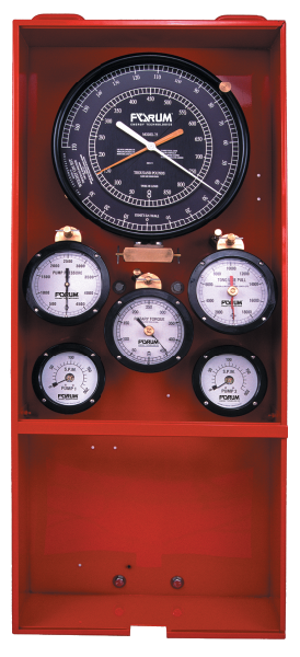
OILFIELD INSTRUMENTS 4:1 vernier movement for sensitive bit weight indications Main Technical Specification Part No. Description &Technical Parameters For deadline loads to 168,000 lb (750 kN) 10, 12, 14, and 16 lines strung E551 compression load cell or E543 Sensater tension load cell 16" indicator 9 MPa For deadline loads to 130,000 lb (580 kN) 10, 12, 14, and 16 lines strung E551 compression load cell or E543 Sensater tension load cell 16" dial indicator 7.49 MPa For deadline loads to 103,400 lb (460 kN) 10, 12, 14, and 16 lines strung E551 compression load cell or E543 Sensater tension...
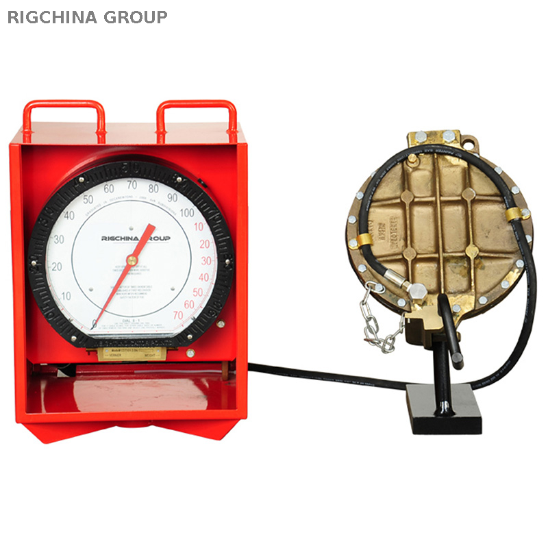
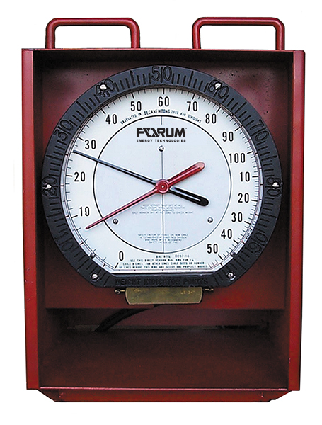
OILFIELD INSTRUMENTS 6, 8, 10, and 12 lines strung E551 compression load cell or E543 Sensater tension load cell 16" dial indicator 5.2MPa For deadline loads to 22,500 lb (100 kN) 4, 6, and 8 lines strung E551 compression load cell or E543 Sensater tension load cell 16" dial indicator 4.2MPa 2. DEFLECTION-TYPE (CLIPPER) WEIGHT INDICATOR Model CDT-1013 For other drilling rig applications, including workover rigs, service rigs and pulling units that do not have conventional wireline anchors, RIGCHINA offers several weight indicator solutions. These include Clipper type weight indicators that...
OILFIELD INSTRUMENTS principle, the tighter the drill line gets the more force is applied to the diaphragm which converts the deflection to hydraulic pressure and sends that pressure to the 12”gauge which displays weight. The whole weight indicator system fits into the steel case for convenient, compact storage. Built-in handles make the entire system easy to transport. FEATURES: 12-inch gauge comes standard. Complete set of 10 dials included from 2-lines 7/8” to 8-Lines 1” Weight Indicator has two pointers, one for weight and the other for sensitivity which is a 6:1 ratio and ideal for...
OILFIELD INSTRUMENTS 2 WIRELINE WEIGHT INDICATORS Wireline Weight Indicators Ideally suited for used by wireline service trucks. Model CW-50 Wireline Weight Indicators Model CW-20 Wireline Weight Indicators FEATURES: -6” or 8.5” fluid filled gauge with dial faces available in decanewtons, pounds, kilograms, or dual scale. -Damper system allows operator to increase or decrease sentivity easily to monitor the minutest changes. -Each system is calibrated in our factory and is shipped precharged and ready to use. Tel: 0086-579-87537698(switchboard) Fax: 0086-579-8753 696 Rev.2015 URL:...
OILFIELD INSTRUMENTS -Calibration and line pull certificates are sent with the system. -Available in the following capacities: 1000, 2000, 3000, 4000, 5000, 6000, and 10,000 pounds. 3 DEADLINE ANCHORS Deadline anchors provide accurate weight measurements and secure deadlines Full line of all-weather, quality-built deadline anchors pull capacities from 30,000 to 160,000 pounds Constructed with top-quality steel and proof-tested to 150% of rated capacity, Deadline Anchors are highly accurate, super-strong anchors of exceptional reliability. RIGCHINA Deadline Anchors are designed to be used...
OILFIELD INSTRUMENTS Size of rig Derrick capacity in pounds Size of drilling wireline Number of lines strung Right or left hand model Tel: 0086-579-87537698(switchboard) Fax: 0086-579-8753 696 Rev.2015 URL: http://www.rigchina.com Email: sales@rigchina.com SKYPE:RIGCHINA Add: No.80-82, Qiude Rd, West Cheng Industrial Estate, Yongkang city Zhejiang Province, China
OILFIELD INSTRUMENTS Main technical specification for deadline anchor (Weight Indicator) Specification Mounting Model of Type of weight Welding(W) deadline indicator anchor Casting(C) Max deadline pulling force (pounds) Deadline Max load numbers (pounds) Left hand model Right Hand Left hand Crown block Tel: 0086-579-87537698(switchboard) Fax: 0086-579-8753 696 Rev.2015 URL: http://www.rigchina.com Email: sales@rigchina.com SKYPE:RIGCHINA Add: No.80-82, Qiude Rd, West Cheng Industrial Estate, Yongkang city Zhejiang Province, China 321
OILFIELD INSTRUMENTS Pull line Pull line Pull line Tel: 0086-579-87537698(switchboard) Fax: 0086-579-8753 696 Rev.2015 URL: http://www.rigchina.com Email: sales@rigchina.com SKYPE:RIGCHINA Add: No.80-82, Qiude Rd, West Cheng Industrial Estate, Yongkang city Zhejiang Province, China 321300
OILFIELD INSTRUMENTS WARRANTY Rigchina Group Company warrants its products to be free from defects in material and workmanship for a period of 24 months from the time of shipment. If repair or adjustment is necessary, and has not been the result of abuse or misuse within the twelve-month period, please return, freight prepaid, and correction of the defect will be made without charge. Out of warranty products will be repaired for a nominal charge. Please refer to the accompanying warranty statement enclosed with the product. RETURNS For your protection, items being returned must be carefully...

A deflection type weight indicator, also known as a line scale or clipper, is ideal for use with work over rigs and small drilling rigs. The complete boxed unit includes a 12” Gauge with interchangeable dials, hose and loadcell. The unit is highly portable and durable.

Look through the extensive range of wholesale drilling rig weight indicator to pick from one of the best weight scales that are available. If you are a business owner who needs to weigh small parcels or outgoing mail, look into the product offerings for the variety of digital pocket scales available. For those who deal with jewelery, there is also a variety of jewelery scales on sale at great prices.
For those who are looking for industrial scales meant to handle heavier items, there are several choices you can pick from. You will be able to find products like truck weight scales and livestock scales in the product listings. Find the drilling rig weight indicator you require at reasonable prices among the products offered.
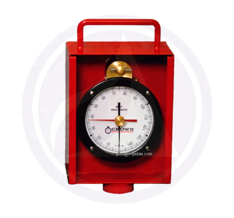
Our mini weight indicator systems, also called “midget indicators”, are ideal for small work over rigs, water well drilling rigs, and geothermal drilling. Our complete mini weight indicator systems are mounted in a compact box for convenient transport and are ready to use, right out of the box. No assembly or loading is required. The load cell attaches easily to the rig without the need for a deadline anchor, and everything you need to install this system is included. Our indicators are designed to provide extremely accurate weight measurement, and the large dial is easy to read at a distance. The 6″ gauge is fluid-filled to resist shock, vibrations, corrosion and dial bounce. This hydraulic system is complete, needing no external power source.
The weight indicator shows 230,000 lbs. The block and lines weight 30,000 lbs. A pump pressure gauge in line with the drillpipe shows 7,000 psi. The drillpipe is 5" by 4.276" by 19.5 ppf and the average weight per foot of the steel in the drillpipe is 21.4 lb/ft. What is the real tension in the drillpipe at the rotary table and at a depth of5,000 feet?
Free rotating weight. It is the weight of the drill string with the string off bottom and while the string is being rotated. The rotary speed should be above 35 rpm.
Pick-up weight. It is the weight of the drill string while raising the string at a normal working speed. Most drillers raise the string too slowly. Be careful not to add in the load of accelerating the drill string and breaking gel of the mud.
Slack-off weight. It is the weight of the drillstring while lowering the string at a normal working speed. The above potentials for error must be once again avoided.
The free rotating weight of a drill string is 200,000 lbs, the pick-up weight is 250,000 lbs, and the slack-off weight is 170,000 lbs. What are the pick-up and slack-off drag loads?

Some history…is what it is, history but every now and then you read some things that bring the message home clearer than others. Take for example the history we are about to share in regard to the weight indicator and how far we have come as an industry.
If you are an experienced person that has spent years on the floor of any drilling rig this will be a very interesting read for you. If you are young and just starting out then here is a history lesson that you will probably not learn in school, especially as colorful as the author has put it here.
The entire weight of the drill string could not be allowed to rest on the bit at the bottom of the hole. Some of this weight had to be borne by the hook. The weight indicator measured the weight of the drilling shaft when the bit was off the bottom of the hole, and the weight of the drilling shaft unsupported by the bit when drilling. There were two general types of weight indicators employed in Alberta, one of which was operated from the deadline and the other from the hook. Both types had indicating gauges, and some had recorders providing a permanent record of the weight carried on the bit, the pull on the pipe, and the round-trip data.
The need for weight indicators had been obvious for a number of years, but in their absence the driller himself functioned as the only "instrument" and he used whatever seemed to work best to determine what the load was. It was important to know how much pull was being exerted when a cable tool or rotary rig was pulling casing or drill pipe, because, from time-to-time, heavy weights on the line or hook caused the derrick to be "pulled in" on top of the crew.
One common problem with all weight indicators was their response to rough usage and the weather. The intense vibration experienced by weight indicators, situated as they were as on the derrick floor, frequently caused the copper tubing carrying the fluid between the wire rope and the gauge"s diaphragm and indicator needle to snap. In cold weather the rubber hose that housed and partially insulated the copper tubing could not prevent the fluid from freezing. In hot weather, the sun shone on these same lines and they expanded, causing the weight measurements to increase; when the lines were in the shade again, the values decreased. Problems with vibration and temperature sensitivity persisted for some years.
The Quintuplex was succeeded by the Martin Decker "Sealtite" weight indicator model which could simultaneously record weight, torque, mud pressure, rotary speed, and the rate of penetration. This unit was also clamped to the deadline at the top and bottom. A deflection plug caused the line to deflect. Increased tension in the deadline tended to straighten it, and increased the pressure against the deflection plug, which passed on the change to the diaphragm and then the indicator needle in the panel.
After 1935, two more weight instruments appeared on the marker and persisted, which improvements, into the late 1940s. The first of these was the Abercrombie weight indicator, attached to the deadline of a cable cool rig casing line or a rotary drilling line. It could be used to indicate the weight in handling casing in and out of the hole, on fishing jobs or retrieving stuck pipe, and to indicate the amount of weight resting on a rotating rock bit. This piece of equipment had the virtue of simplicity; it was entirely mechanical; and easy to connect to the deadline. The dial of this indicator read directly in pounds and could be adjusted to permit the driller to read more than one line. The second indicator to appeared in Alberta in the 1930s was the Line Scale Weight Indicator. Attached to the deadline of the casing or drilling line, it indicated the weight directly in pounds by multiplying the increase or decrease in the bend in the line when it was put under load. It used the mechanical force of a deflected line to actuate a lever (against resistance of a spring), which moved an indicator on the dial. It was said to be a "tiny bit hardier" than most other indicators.
The Cameron Iron Works entered the competition for weight indicators during the 1930s and brought out several models before producing a sturdy one in the form of their Type C. It was a completely mechanical model with no recorder and was clamped to the deadline. The Cameron model Type E was similar to the Type C and also clamped co the deadline, but it differed in that it measured directly into pounds rather than a scale of numbers indicating a degree of heaviness.
The Hook-Load indicator, employing both hydraulic and electric or electronic operating principles, appeared in the early 1950s. Manufactured by the Byron Jackson Company, it measured strain in the hook through the use of resistant type electric strain gauges placed on the load-carrying equipment. After some teething problems, they became a viable alternative to the line-type weight indicators.
Martin Decker Corporation and National Supply Company developed a weight indicator using a completely new operating principle. It was known as the Type D Combination Weight Indicator and Wire Line Anchor. The Wire Line Anchor was a pair of levers, one of which formed the base and was fixed to the rig floor or derrick foundation, while the other formed a wheel or drum around which the deadline was snubbed with two or three turns. Loads applied to the deadline rotated the drum within the limit of a series of stops. The two levers were joined at their extreme ends by a hydraulic pressure transformer which resisted the rotational force of the drum. The rotational force was thereby transformed into hydraulic pressure, which in turn was transmitted to a gauge and recorder at the driller"s position. Hook load was shown in thousands of pounds. This line was more trouble-free than previous ones, according to George Fyfe, although it was also expensive and at first, not all rig owners were eager to put out the money to buy one.
By 1958, three types of weight indicators were on the marker: Those based on the hook load principle; instruments attached to the deadline; and an instrument composed of a pressure transformer and indicating gauge connected by a hydraulic hose. George Fyfe confirms that eventually this third type of instrument became the most favored because it was more reliable and more rugged than the older models in a business where reliability and the ability to withstand rough handling are paramount.

A pit in the ground to provide additional height between the rig floor and the well head to accommodate the installation of blowout preventers, ratholes, mouseholes, and so forth. It also collects drainage water and other fluids for disposal.†
A small enclosure on the rig floor used as an office for the driller or as a storehouse for small objects. Also, any small building used as an office or for storage.†
The hoisting mechanism on a drilling rig. It is essentially a large winch that spools off or takes in the drilling line and thus raises or lowers the drill stem and bit.†
A heavy, thick-walled tube, usually steel, used between the drill pipe and the bit in the drill stem. It is used to put weight on the bit so that the bit can drill.†
On diesel electric rigs, powerful diesel engines drive large electric generators. The generators produce electricity that flows through cables to electric switches and control equipment enclosed in a control cabinet or panel. Electricity is fed to electric motors via the panel.†
Shallow bores under the rig floor, usually lined with pipe, in which joints of drill pipe are temporarily suspended for later connection to the drill string.†
A diesel, Liquefied Petroleum Gas (LPG), natural gas, or gasoline engine, along with a mechanical transmission and generator for producing power for the drilling rig. Newer rigs use electric generators to power electric motors on the other parts of the rig.†
A hole in the rig floor 30 to 35 feet deep, lined with casing that projects above the floor. The kelly is placed in the rathole when hoisting operations are in progress.†
Shallow bores under the rig floor, usually lined with pipe, in which joints of drill pipe are temporarily suspended for later connection to the drill string.†
The hose on a rotary drilling rig that conducts the drilling fluid from the mud pump and standpipe to the swivel and kelly; also called the mud hose or the kelly hose.†
The top drive rotates the drill string end bit without the use of a kelly and rotary table. The top drive is operated from a control console on the rig floor.†

This website is using a security service to protect itself from online attacks. The action you just performed triggered the security solution. There are several actions that could trigger this block including submitting a certain word or phrase, a SQL command or malformed data.
Stuck pipe is one of serious situations that sometimes happen on the rig. People put a lot of effort to free stuck pipe; however, when they reach the point that they can not free the pipe anymore, they may need to know where the stuck point is in order to plan to cut or back off drill pipe. This post will demonstrate you how to determine free point constant and calculate where a stuck point is.

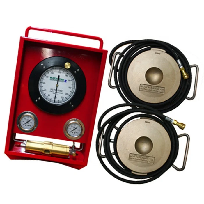
Matherne Instrumentation’s pad type weight indicator systems are used in applications where either there is no dead line or a double fast line is being used. Pad type load cells detect mast loading under mast jack screws independent of reeving configuration. Our system is housed in a heavy duty steel box with removable front and back doors for added protection. A two-inch coupling is welded to the bottom of the box for easy installation and high visibility. For more information about our drilling rig weight indicators or to request a quote, feel free to contact us today! We"re proud to supply our weight indicator systems to clients throughout Odessa, TX; Midland, TX; Houston, TX; Lafayette, LA; Houma, LA; Pittsburgh, PA; and Williston, ND.
Another way of labeling kicks is by identifying the required mud weight increase necessary to control the well and kill a potential blowout. For example, if a kick required a 0.7-lbm/gal (84-kg/m3) mud weight increase to control the well, the kick could be termed a 0.7-lbm/gal (84-kg/m3) kick. It is interesting to note that an average kick requires approximately 0.5 lbm/gal (60 kg/m3), or less, mud weight increase.
Insufficient mud weight is the predominant cause of kicks. A permeable zone is drilled while using a mud weight that exerts less pressure than the formation pressure within the zone. Because the formation pressure exceeds the wellbore pressure, fluids begin to flow from the formation into the wellbore and the kick occurs.
These abnormal formation pressures are often associated with causes for kicks. Abnormal formation pressures are greater pressures than in normal conditions. In well control situations, formation pressures greater than normal are the biggest concern. Because a normal formation pressure is equal to a full column of native water, abnormally pressured formations exert more pressure than a full water column. If abnormally pressured formations are encountered while drilling with mud weights insufficient to control the zone, a potential kick situation has developed. Whether or not the kick occurs depends on the permeability and porosity of the rock. A number of abnormal pressure indicators can be used to estimate formation pressures so that kicks caused by insufficient mud weight are prevented (some are listed in Table 1).
An obvious solution to kicks caused by insufficient mud weights seems to be drilling with high mud weights; however, this is not always a viable solution. First, high mud weights may exceed the fracture mud weight of the formation and induce lost circulation. Second, mud weights in excess of the formation pressure may significantly reduce the penetration rates. Also, pipe sticking becomes a serious consideration when excessive mud weights are used. The best solution is to maintain a mud weight slightly greater than formation pressure until the mud weight begins to approach the fracture mud weight and, thus, requires an additional string of casing.
Although the mud weight is cut severely at the surface, the hydrostatic pressure is not reduced significantly because most gas expansion occurs near the surface and not at the hole bottom.
Warning signs and possible kick indicators can be observed at the surface. Each crew member has the responsibility to recognize and interpret these signs and take proper action. All signs do not positively identify a kick; some merely warn of potential kick situations. Key warning signs to watch for include the following:
An increase in flow rate leaving the well, while pumping at a constant rate, is a primary kick indicator. The increased flow rate is interpreted as the formation aiding the rig pumps by moving fluid up the annulus and forcing formation fluids into the wellbore.
When the rig pumps are not moving the mud, a continued flow from the well indicates a kick is in progress. An exception is when the mud in the drillpipe is considerably heavier than in the annulus, such as in the case of a slug.
Drilling fluid provides a buoyant effect to the drillstring and reduces the actual pipe weight supported by the derrick. Heavier muds have a greater buoyant force than less dense muds. When a kick occurs, and low-density formation fluids begin to enter the borehole, the buoyant force of the mud system is reduced, and the string weight observed at the surface begins to increase.
An abrupt increase in bit-penetration rate, called a “drilling break,” is a warning sign of a potential kick. A gradual increase in penetration rate is an abnormal pressure indicator, and should not be misconstrued as an abrupt rate increase.
Fortunately, the lower mud weights from the cuttings effect are found near the surface (generally because of gas expansion), and do not appreciably reduce mud density throughout the hole. Table 3 shows that gas cutting has a very small effect on bottomhole hydrostatic pressure.
An important point to remember about gas cutting is that, if the well did not kick within the time required to drill the gas zone and circulate the gas to the surface, only a small possibility exists that it will kick. Generally, gas cutting indicates that a formation has been drilled that contains gas. It does not mean that the mud weight must be increased.
Drilling-efficiency data, such as downhole weight on bit and torque, can be used to differentiate between rate of penetration changes caused by drag and those caused by formation strength. Monitoring bottomhole pressure, temperature, and flow with the MWD tool is not only useful for early kick detection, but can also be valuable during a well-control kill operation. Formation evaluation capabilities, such as gamma ray and resistivity measurements, can be used to detect influxes into the wellbore, identify rock lithology, and predict pore pressure trends.
The MWD tool offers kick-detection benefits, if the response time is less than the time it takes to observe the surface indicators. The tool can provide early detection of kicks and potential influxes, as well as monitor the kick-killing process. Tool response time is a function of the complexity of the MWD tool and the mode of operation. The sequence of data transmission determines the update times of each type of measurement. Many MWD tools allow for reprogramming of the update sequence while the tool is in the hole. This feature can enable the operator to increase the update frequency of critical information to meet the expected needs of the section being drilled. If the tool response time is longer than required for surface indicators to be observed, the MWD only serves as a confirmation source.
It is necessary to calculate the mud weight needed to balance bottomhole formation pressure. “Kill-weight mud” is the amount of mud necessary to exactly balance formation pressure. It will be later shown that it is safer to use the exact required mud weight without variation
Because the drillpipe pressure has been defined as a bottomhole pressure gauge, the psidp can be used to calculate the mud weight necessary to kill the well. The kill mud formula follows:
Because the casing pressure does not appear in Eq. 2, a high casing pressure does not necessarily indicate a high kill-weight mud. The same is true for pit gain because it does not appear in Eq. 2. Example 1 uses the kill-weight mud formula.

Pipe recovery is a specific wireline operation used in the oil and gas industry, when the drill string becomes stuck downhole. Stuck pipe prevents the drill rig from continuing operations. This results in costly downtime, ranging anywhere from $10,000-1,000,000 per day of downtime, therefore it is critical to resolve the problem as quickly as possible. Pipe recovery is the process by which the location of the stuck pipe is identified, and the free pipe is separated from the stuck pipe either by a backoff or a chemical cut. This allows fishing tools to subsequently be run down hole to latch onto and remove the stuck pipe.
The geological formation downhole occasionally has a significantly lower pressure than the drilling fluid being used. When the pipe string comes into contact with the exposed formation the difference in pressure will cause the pipe to be sucked against the formation. If the rig is able to circulate drilling fluid back to the surface that is often a good indication of differentially stuck pipe. One technique for freeing the stuck pipe, or avoiding the issue to begin with, is to rotate the pipe string while pulling out of the hole.
Key seating occurs when the drill string becomes off-centered in the wellbore, and the pipe collars become caught on a deviation in the wellbore. If the rig is able to move the drill string freely downhole, but every time the drill string is pulled upward it becomes stuck at the same point, then it is likely that the pipe is caught in a key seat.
The term free point is used to describe the delineating point between the stuck pipe and the free pipe in a pipe string. Every joint of pipe above the free point is free, meaning it can rotate freely and be moved in and out of the hole, provided it was not attached to the remaining joints of stuck pipe below the free point. A good way to visualize this is to hold a piece of string with your left hand. With your right hand grab the bottom third of that string. The 2/3rds of the string above your right hand would be considered free, since you can move the string however you may like. The section of string inside and below your right hand is stuck, since no matter what you do to the free string it will not affect the string in or below your right hand.
Pull the drillstring to the pipe"s neutral weight, which is the combined weight of blocks and the weight of the drill string and make a mark(X1)(in) at the top of the rotary table.
Identify the recommended overpull by multiplying 2208.5 by pipe weight/ft. Pull the calculated overpull(F) (Not to exceed the yield strength of the pipe) causing the free portion of the pipe to stretch to a new position (X2)(in).
where Lsp = depth of stuck point (ft), (X2-X1)= The stretch of the pipe from the reference point (in.), Wdp = weight of drill pipe (lbs/ft), and F = the additional pull required (lbs.) It is important to note that the stretch test does not take into account drill collars, heavyweight drill pipe, and/or wellbore deviation.
The Halliburton Freepoint Tool is based around the magnetorestrictive property of steel. This principle states that when torque or stretch is applied to free pipe, the magnetization will change. Stuck pipe will have no change in magnetization. There is a magnet on the bottom of the tool that creates a small magnetic field. There are four co-planar orthogonal multi-axis high sensitivity magnetometers located above the magnet. The magnetometers measure the change in the magnetization of the pipe. The pipe is set at neutral weight, then the tool is run downhole logging the entire pipe string. Once it is at the bottom of the string, torque or stretch is applied to the pipe. The tool is then pulled uphole logging the entire string. The tool will detect differences in the magnetization of the pipe, thereby indicating free and stuck sections of pipe.
Manual back offs are the least preferred technique for removing free pipe from the hole since there is very little control. When performing a manual back off you take the desired back off depth(ft.) and multiply it by the weight of one foot of pipe. This will give you a rough estimate of the neutral weight of the pipe at the desired depth. By setting the pipe at neutral weight at the desired depth you are reducing any tension on the threads at the desired depth, thereby increasing your odds of the pipe unscrewing there. The driller will pickup the string to the back off neutral weight, and then left hand torque is applied until the pipe unscrews. There is no guarantee that the pipe will unscrew at the desired point making the manual back off the last resort for backing off pipe.
The Drill Collar Severing Tool is often used to separate heavy weight drill pipe or drill collars. The DCST contains an explosive charge at either end of the tool; both charges are detonated simultaneously. The explosive shock waves meet in the center of the tool and combine to produce a very high energy wave capable of cutting through the thickest of pipe. The severed pipe is typically split and deformed, requiring milling.


 8613371530291