
parker hydraulic pump rotation direction in stock
Gear pumps have an input shaft that drives an inner gear or “drive” gear. When the shaft turns the drive gear, the drive gear turns the “driven” gear. As these two gears rotate, oil is pulled into the suction port, split and carried around the perimeter of the gears, and finally, combined and pushed out the discharge port.
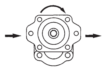
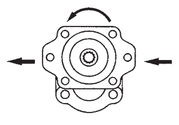
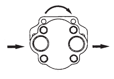
When determining the rotation of a gear pump, one must decide on the viewing orientation. As an industry standard a pump’s rotation is determined when viewed looking at the input shaft. If your viewing orientation is at the rear of the pump, the technical rotation of the pump is opposite the visual rotation.
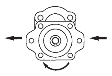
The suction and discharge ports are determined by the rotation of the input shaft. As with rotation, the position of each port is dependent upon the viewing orientation. Here to, the industry standard, when looking at the input shaft, is for the drive gear to be oriented above the driven gear, also known as “belly down”. In this orientation, a clockwise pump will have suction on the left and discharge on the right and vice versa. If the pump is oriented with the “belly up”, the suction and discharge ports will appear opposite.
We carry major manufacturers like Allen-Bradley, Allison Transmission, Autocar Truck, Bendix, Braden Carco Gearmatic, Caterpillar, Clark, Clark Michigan, Cummins Engine, Dana-Off Highway, Dana Spicer Heavy Axle, David Brown, Deutz Diesel, Detroit Diesel, Eaton, Eaton-Fuller, Eaton-Vickers, Fiat Allis, FWD, Gates, Hitachi, Horton, Hyundai Construction Equipment, Ingersoll-Rand Pneumatic Tool, John Deere Construction & Forestry, Koehring Cranes & Excavators, Komatsu America, Komatsu America-Wabco, Kubota Engine, Meritor, Meritor Wabco, Parker, Perkins, Rexroth GMBH, Robert Bosch, Red Dot, SKF Bearings, Timken, ZF Parts and hundreds of others.
We cover a broad range of categories including Hydraulics, Engines, Transmissions, Gears, Hose and Fittings, Pumps, Valves, Cylinders, Shock Absorbers, Brakes, Axles, Bearings, Filters, Electric Motors, Gauges, Forklift Parts and many more. We serve repair facilities, maintenance departments, owner-operators, manufacturers, distributors and resellers. Basically, anyone who needs parts. Our website is searchable by part number, manufacturer, description and other key words.
For hydraulic pump installation or when replacing a hydraulic pump or motor, it is essential that all critical parameters are taken into account. Be sure you know the required system, pressure, RPM range, direction of rotation, shaft size and type, port size and type, and mounting information. If you have nay questions regarding replacing pumps, don’t hesitate to call our component group at 1-800-728-5168.
In many cases, OEM’s have used pumps from several different manufacturers for the same model of equipment and are, for all practical purposes, identical.
Using the above information, our trained personnel will select the proper replacement pump. Some pumps, however, have been out of production for a number of years and certain modifications may have to be made
Gear pumps,piston pumps and probably vane pumps can be set up to run in either direction. Your pump has a pipe connected from the tank to the pump,then from the pump to the valving,then to a hydraulic motor or cylinder.There will be a line running back to the tank.This line will be under low pressure,but with lots of flow.It should be below the oil level in the tank,to reduce foaming. One direction of motor rotation will send oil through the valves and to the hyd. motor. The other direction,the pump won"t do any pumping at all.Use two wrenches and slightly loosen the fitting on the line going to the hydraulic motor,or ram,while the electric motor is running.You should see hydraulic oil start to seep.DON"T FEEL FOR ANY OIL LEAKING!!Hydraulic oil under pressure,= amputation,or poisoning! Check for the level of oil in the tank to be above the intake pipe at all times. Do you have any visible hydraulic leaks? Do you have a vaccum tight connection from the tank to the pump? There might be a internal screen and or filter inside the tank. Did you lose hydraulic pressure gradually,or all at once? There will be a relief valve somewhere in the system,they sometimes hang up in the open position.You probably have electric valves controling the operations. Check to see that they are working.Occasionally they hang up.Any valve staying open would dump oil back to the tank,reducing the pressure in the system to below that needed to actuate any other motor,or rams. Check for hoses that are broken,or leaking.Good luck!
Cartridge kits are available with different port plates allowing either uni-directional or bi-directional rotation. All T7 and all T6 mobile cartridge kits (both up to size E) are bi-directional; this is an option available to most T6 industrial cartridges as well. Bi-directional means that you can change the direction of rotation of the pump without the need of extra parts.
The Denison Hydraulics T-Series started off with the introduction of the T1 Series single vane pump in 1950 followed by the T2 and T3 Series single and multiple vane pumps in the early 1960s. Further development and continuous improvement of the Denison Vane Technology resulted in the higher pressure capability and range of speeds we know today.
When replacing simple gear pumps that are either obsolete or of an unknown manufacturer, there are several factors to consider. Please be ready to supply the following information below so one of our Hydraulic Specialists can assist you in locating a possible replacement. It may be necessary to know the intended application of the pump as potential side loading of a pump can determine whether a bushing or bearing pump should be used.
Common pump shafts used in the North America usually fall within four categories; keyed, splined, tapered, or tang. Keyed and spline shafts come in many various sizes and lengths; the most common shafts may be identified using the charts below. Tapered and tang drive shafts are typically application specific, please supply the information from the corresponding figures below.
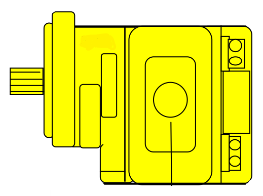
Pump rotation is always determined with the pump input shaft facing towards the user with the belly of the pump facing down. Gear pumps will have a shaft that is located in the center of the mounting flange that directly connected to a gear. This gear in turn drive the accompanying gear residing in the “belly” portion of the pump.
In a simple gear pump circuit, there are only two lines that connect to the pump. They supply oil from the reservoir, and send the pressure to the system. There are a myriad of hydraulic fitting thread types and sizes. The three most common fitting types that we see used on pumps in the North American market are NPT, SAE O-ring Boss, and SAE O-ring Flange.
NPT stands for National Pipe Taper. Pipe sizes are determined by the inside diameter of the pipe resulting in the thread size to measure nominally larger. For example the outside thread dimension of a ½”NPT fitting actually measures closer to ¾”. The NPT fittings are narrower on one end vs the other. This allows the fitting to “tighten” as the fitting is threaded in. There is a critical difference in pressure ratings between hydraulic rated NPT fittings and those designed for the plumbing and gas industries. Even though they share the same thread dimensions, plumbing fittings should never be used in hydraulics. Pipe thread seals by the galling of the surface are between the metal threads. That is why you should only use a recommended Teflon Paste when using NPT fittings in hydraulics. The paste acts as a lubricant allowing the fitting to make a tighter more efficient seal. The use of pipe tape is strongly discouraged for hydraulic systems.
SAE O-ring Boss straight thread fittings seal with an o-ring at the base of the fitting. The fittings sizes are determined by the inside diameter resulting in the thread size to measure nominally larger. For example, the outside thread dimension of a #6 SAE fitting actually measures 9/16” outside diameter with 18 threads per inch. Most modern hydraulic gear pumps are now using the SAE O-ring boss fittings as they have proven to suffer fewer failure rates for leakage.Some of the most common fitting sizes and types are listed in the chart below:
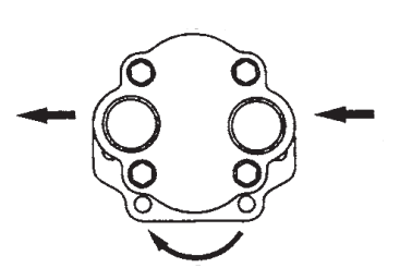
Porting location on gear pumps usually come in either the side or the rear of the pump. There are some replacement pumps that include both side and rear ports. Only one inlet and one outlet should be used. The unused port will need to be blocked off with a hydraulically rated plug.
The volume of oil that Gear pump can flow is determined by the pump displacement and the speed at which it is rotated. Displacement is typically given in cubic inches per revolution or cubic centimeters per revolution.
To determine the unknown displacement of a pump it is necessary to disassemble it to take internal measurements. You will need to measure the outside diameter of one of the gears, the height or thickness of the gear, and the distance from the center to center of the two gears as they are mounted into the pump housing. Below you will find a guide with the formula required to determine the displacement.
Within the hydraulic industry is typically rated in pounds per square inch (psi) or BAR. Ensuring the pump that you are selecting as a replacement is rated for the pressure your system will require is a critical yet often overlooked step. As the displacement goes up within a particular frame size the acceptable working pressure will decrease. It may be necessary to change to a larger frame size to avoid excessive strain on the pump causing premature wear. Remember there is typically a reason that your original pump failed. Gear pumps can be rated from very low pressure for fluid transfer applications to over 4000psi in high pressure industrial environments.
As the displacement goes up within a particular frame size the maximum revolutions per minute (RPM) will decrease. It may be necessary to change to a larger frame size to avoid excessive strain on the pump causing premature wear. Remember there is typically a reason that your original pump failed. Gear pumps typically need a minimum RPM to function efficiency as well. It may be necessary to change the rpm range in which the pump is driven to achieve the required efficiency. If the pump is not directly driven it might be possible by changing a gear, sprocket, or pully diameter. Potential side loading of a pump may change. Anticipated side load may determine whether a bushing or bearing pump may be necessary.


 8613371530291