
pedal hydraulic pump free sample
The ESCO Pro Series 1/2 Gallon Air Hydraulic Pump is specifically designed for automotive, light truck, and heavy-duty applications. This pump is constructed with the user in mind, as a compact lightweight air hydraulic pump solution that delivers a powerful punch; requiring only 80 PSI for 10,000 PSI of operating hydraulic pressure to power even the heaviest of cylinders, ram, bead breakers, and more. Built-in exhaust muffler promotes safer, quieter operation along with a robust foot pedal providing hand-free pumping and release of load. Manufactured with the highest of quality parts and components designed to withstand rigorous use in any environment. All ESCO air hydraulic pumps are designed with fully serviceable pump motors, allowing for economical repairs and maintenance. The aluminum reservoir is lightweight and durable for field, shop, and mobile applications.
The Power Team P-Series hand pumps come in a variety of configurations to meet the requirements of your application. Along with various oil capacities and flow rates, you can choose from the following options:
Compact design ensures that the Power Team PA6 series pump is lightweight and portable. The PA6 series consists of single-speed pumps designed to drive single-acting cylinders. The power unit of choice for major manufacturers of auto body, frame straighteners and other equipment. Operates at 40-100 psi (3-8 bar) shop air pressure at the pump, dBA 85 at 10,000 psi (700 bar). Serviceable pump motor is not a “throwaway”, providing economical repair. Permanently vented reservoir cap. Internal relief valve protects circuit components, air inlet filter protects motor.
Compact, lightweight and portable the Power Team PA6D series pumps are single-speed pumps for driving double-acting cylinders. The PA6D series pumps operate at 40-100 psi (3-8 bar) shop air pressure at the pump. Designed with longevity in-mind the PA6D series feature internal relief valve protects circuit components, air inlet filter protects motor. Serviceable pump motor is not a “throw away”, providing economical repair. Permanently vented reservoir cap. dBA 85 at 10,000 psi (700 bar) for all PA6 pump.
Ideal for powering single-acting cylinders and portable hydraulic tools, the Power Team PA9 series pumps are easier to operate than a hand pump, designed for efficiency. Built to be economical in service; the PA9 series is not a “throwaway” unit. Unique bladder design for all-position operation and storage. Operates on 40-120 psi (3-8 bar) shop air, at 20 cfm (570 l). Hard-coat anodized aluminum housing. Oil filler with integral safety relief minimizes chance of damage to reservoir bladder if overfilling occurs.
A two-speed pump, the Power Team PA60 series pumps are designed for rapid oil delivery at low pressure to quickly advance cylinder or tool. Equipped with air pressure regulator, air filter and lubricator. Serviceable air motor for economical repair. Internal relief valve protects circuit components. Permanently vented reservoir cap.
Focused on single-speed and low pressure the Power Team PA50 series pump outputs 3,200 PSI / 220 BAR, fitting serviceable requirements for air motor for economical repair. Integrated air inlet filter protects motor. The PA50 series also features a filter in outlet port protects against contaminated systems Assorted reservoirs to suit your application"s requirements.
Rotary-Style Air Motor. Use where air is the preferred source of energy. 3 hp motor starting under full load. Two-speed operation for rapid cylinder advance. Models available with full remote control over advance and return, except PA554. Tandem center valve holds the load when pump is shut-off.
Compact, Portable, Cordless Hydraulic Pump for MRO Applications. Compact, Li-ion 18VDC, 9.0 Ah battery-powered pump provides extended run-time. Two-stage, high-pressure hydraulic pump offers quick tool advancement in the first stage. Extremely compact, lightweight with an ergonomic handle grip and transport strap to ease portability. Self-contained, rubber bladder reservoir allows pump usage in most positions with an impressive capacity of 70 cu. in. usable. Quiet, smooth-running, serviceable brushed 18VDC motor. High-impact, fiberglass reinforced shroud protects your investment in the most demanding and harsh applications. Interchangeable valve configuration accommodates a vast array of applications. CSA rated for intermittent duty, CE compliant.
The 10 series Power Team hydraulic pumps are designed to have a maximum of 690 bar (10,000 psi) at a flow rate of 164 cc/min (10 cu. in/min). All Power Team pumps come fully assembled, and each with the ability to be valved for either single- or double acting cylinders. Designed to be compact can easily mobile, the power team 10 series includes a portable power source is included for hydraulic cylinders, and tools. The permanent magnet motor is strategically constructed to easily start under load, even with reduced voltage conditions. Battery-operated models have 8 foot (2,4 m) power cord with alligator clips to connect to any 12 volt battery, optional rechargeable battery pack with shoulder strap are alternatives for maximum portability. The Power Team 10 series pump typically delivers 15 minutes of continuous operation at 10,000 psi (700 bar) on a single battery. Built to withstand High-impact, shielded with a flame retardant construction.
The Power Team 17 series pump is delibertly designed for maintenance and construction applications up to 55 Ton. For use with single-acting or double-acting cylinders at operating pressures to 10,000 psi (700 bar). For intermittent duty; starts under full load. Equipped with 1⁄2 hp (0,37 kW), 3,450 rpm, single-phase, thermal protected induction motor; 10 ft. remote control cord (PE172S has 25 ft. (7,6 m) cord) Low amperage draw; small generators and low amperage circuits can be used as power source. Extremely quiet noise level (67-81 dBA).
Vanguard Jr. + Power Team 18 series pumps provide two-speed high performance in a light-weight, compact package. Designed to provide a gauge port and metal reservoir on all pump models. Equipped with a 1⁄2 hp (0,37 kW), 115 volt, 60/50 Hz single phase motor that starts under load, even at reduced voltage. Low amperage draw permits use with smaller generators and low amperage circuits. All pumps have a 10 foot (3 m) remote control. CSA rated for intermittent duty. Noise level of 85-90 dBA. For operating hydraulic crimping, cutting or other tools: No. PE184C - Allows you to alternately operate a spring-return cutting and/or crimping tool without disconnecting either tool. Select a port connection with a manual 4-way valve, start the pump with a remote control hand switch and extend the connected tool. When the hand switch is switched to off, the pump stops and the automatic valve opens, allowing the tool to return. In the center (neutral) position, a manual control valve holds the tool in position at the time valve is shifted.
The 21 series Power Team pump and RD5513 cylinder used in a special press that produces pharmaceutical-grade extracts for herbal medicines. Totally enclosed, fan cooled induction motor: 1 hp (0,75 kW), 1,725 rpm, 60 Hz, single phase. Designed intentional for thermal overload protection. Remote control, with 10 foot (3,1 m) cord is standard on pumps with solenoid valves. Manual valve pumps have “Stop”, “Start” and “Run/Off/Pulse” switches. Pump controls are moisture and dust resistant. Motor drip cover with carrying handles and lifting lug. Low noise level of 70 dBA@ 10,000 psi (700 bar). In the event of electrical interruption, pump shuts off and will not start up until operator presses the pump start button. 24 volt control circuits on units with remote controls provide additional user/operator safety.
Ideal for running multiple tools or cylinders from one power unit. Recommended for cylinders up to 75 tons. Two-speed pumps have the same low pressure and high pressure flows from both valves. Flows and pressures of each pump are independent. Delivers 300 cu. in./min. of oil at 100 psi (4,8 liter/min of oil at 7 bar) and 25 cu. in./min. at 10,000 psi (0,4 liter/min at 700 bar) from each pump. 1 1/2 hp, 110/115 volt, 60 Hz (1,12 kW, 220 volt, 50 Hz) induction motor, 10 foot (3,1 meter) remote control and 5 gallon (19 liter) steel reservoir. Models available for operating single-acting or double-acting cylinders. Each power unit contains two separate pumps and two separate valves allowing operator to control multiple processes with one power unit. Both pumps on each power unit are equipped with an externally adjustable pressure relief valve. Not recommended for frequent starting and stopping.
The Power Team 30 series pump is intently ideal for maintenance and construction applications. Operating both single-acting or double-acting cylinders. A dynamically built, Integral roll cage protects the 30 series pump from many forms of damage. 1 hp (0,75 kW), single phase, permanent magnet motor. High performance to weight ratio. Starts under full load even when voltage is reduced to 50% of nominal rating. Quit operations: 82 dBA @ 10,000 psi (700 bar) and 87 dBA @ 0 psi (0 bar). CSA rated for intermittent duty. Remote controls and/or solenoid valves feature 24 volt controls.
The Power Team 46 series is best suited for under the roof maintenance and production applications. Equipped with two-speed high-performance pump, for use with single- or double-acting cylinders at operating pressures to 10,000 psi (700 bar) the 46 series pump is versitile. With a 1 1⁄2 hp (1.12 kW), 3,450 (2,875) rpm single-phase, 60 (50) Hz thermal protected induction motor that starts under full load. Noise level of 77-81 dBA. All equipped with a 10 foot (3,1 m) remote control except PE462S which has a 25 foot (7,6 m) remote control. 24 volt control circuit on all units with remote control. CSA rated for intermittent duty.
A powerful multifaceted pump, the Power Team 55 pump excels at multiple applications. From heavy construction to concrete stressing this pump series is designed for intensity. With low voltage starting possible, the 50/60 Hz universal motor; draws 25 amps at full load, and can start at reduced voltage. CSA rated for intermittent duty. 10 foot (3,1 m) remote motor control (except PE552S which has a 25 foot (7,6 m) remote motor and valve control). True unloading valve achieves greater pump efficiency, allowing higher flows at maximum pressure. Reservoirs available in sizes up to 10 gallons (38 liter). Lightweight and portable. Best weight-to-performance ratio of all Power Team pumps. “Assemble to Order” System: There are times when a custom pump is required. Power Team’s “Assemble to Order” system allows you to choose from a wide range of pre-engineered, off-the shelf components to build a customized pump to fit specific requirements. By selecting standard components you get a “customized” pump without “customized” prices. All pumps come fully assembled, add oil and ready for work.
A compact lightweight pump, the Power Team 60 series is designed for rugged applications and low voltage starting. Experiencing a long, trouble-free life in the most demanding work environments, the 60 series is durable.. Powered by 1 1⁄8 hp, 115 volt, 60/50 Hz (0,84 kW, 220 volt, 60/50 Hz) single phase motor. Starts under load, even at the reduced voltages at construction sites. Optional fan-driven external oil cooler includes rollover guard. Insulated carrying handle. Integral 4" (102 mm) diameter fluid-filled pressure gauge with steel bezel complies with ASME B40.1 Grade A. 0 to 10,000 psi (0 to 700 bar) pressure range in 100 psi (7 bar) increments. Sealed 3⁄4 gallon (4,34 liter (usable) reservoir. Reservoir drain port is standard. Standard oil level sight gauge for accurate oil level monitoring. External spin-on filter removes contaminants from circulating oil to maximize pump, valve and cylinder/tool life.
The Power Team PQ60 series pumps are designed specifically for heavy-duty, extended cycle operation. Integrating single- or double-acting cylinders the PQ60 series is versatile. Constructed for longevity by employing a metal shroud keeps dirt and moisture out of motor and electrical components. An electrical shut-down feature prevents unintentional restarting of motor following an electrical service interruption. Internal relief valve limits pressure to 10,000 psi (700 bar). External relief valve is adjustable from 1,000 to 10,000 psi (70 to 700 bar). The Power Team PQ60 pumps operate below maximum OSHA noise limitation (74-76 dBA). Start and operate under full load, even with voltage reduced by 10%.
The Power Team 120 series pump is exactingly designed for heavy duty, extended cycle operation up to 400 Ton. Built in grit, the series 120 pump can start and operate under full load, even with voltage reduced 10%. An electrical shut-down feature prevents unintentional restarting of motor following an electrical service interruption. Internal relief valve limits pressure to 10,000 psi (700 bar) and an external relief valve is adjustable from 1,000 to 10,000 psi (70 to 700 bar). Pump prewired at factory with a 3 hp, 460 volt, 60 Hz (2,24 kW, 380 volt, 50 Hz), 3 Phase motor. Other electrical configurations are available. 24 volt control circuits on units with remote controls for added user/operator safety. 3 hp (2,24 kW) 3 phase motor with thermal overload protection. Motor starter and heater element supplied as standard equipment; with an intentionally designed metal shroud to keep dirt and moisture out of motor and electrical components. Pumps operate below maximum OSHA noise limitation.
With high tonnage double-acting cylinders, the Power Team 400 series offers both single or multiple cylinder applications. Two-speed high output pump delivers up to 5 gpm (16 liter/min) of oil, with a low noise level of 73-80 dBA. Integral electrical shut-down feature prevents unintentional restarting of motor following an electrical service interruption. Over-current protection prevents damage to motor as a result of overheating. “Stop” and “Start” control buttons are 24 volt. PE4004 has a 4-way/3-position manual valve. The PE4004S has a 4- way/3-position solenoid valve with a 24 volt remote hand switch. External pressure relief valve is adjustable from 1,500 to 10,000 psi (100 to 700 bar). Heavy duty 4" (50,8 mm) diameter casters assure easy maneuvering. 20 gallon (3,927 cu. in. usable) / 75,7 liter (62,8 liter usable) reservoir has a low oil level sight gauge. Powered by a dual voltage 10 hp (7,46 kW), 3 phase, 1,725 (1,437) rpm motor. 3 phase motor has all the electrical components necessary to operate the pump.The customer has no hidden charges when making purchase. Deliver 1,200 cu. in./min. (16 liter/min) of oil @ 200 psi (15 bar), 420 cu. in./min. (5,6 liter/min) of oil @ 10,000 psi (700 bar).
Power team synchronized lifting and lowering system, the MCS ( motion controller system ) series can be used in many hydraulic applications where load position is critical, requiring cylinder synchronization. Whether it is a bridge, a building or any kind of heavy load, with the SPX FLOW power team motion control system, lifting, lowering, pushing, pulling, tilting or positioning loads can be carried out automatically with a high degree of accuracy. The PLC-controlled system is a combination of digital actuation and digital control providing significant advantages such as time savings, repeatability, and extremely low internal stress in the object one is moving. The system also provides documentation for the movement performed.
Extremely durable yet lightweight and operable under low-line voltage conditions, the Power Team PE-NUT series pumps are constructed for challenging conditions. A 115V 5/8 hp (0,46 kW) universal electric motor (50/60 cycle), employing a two-stage pump for efficiency and designed for use with spring-returned remote tools. The PE-NUT series pumps also feature high-pressure safety relief valve, remote hand control with 10-foot (3,1 meter) cord, and a pressure matched quick-coupler supplied. The PE-NUT series uniquely utilizes intermittent duty, piston-type high-pressure pump supercharged by a low-pressure pump. CAUTION: DESIGNED FOR CRIMPING APPLICATION ONLY! This system should not be used for lifting.
Gasoline power ideal for remote locations. A logical choice at work sites where electricity or compressed air are unavailable. For single or double-acting cylinders at operating pressures up to 10,000 psi. All gasoline engine/hydraulic pumps feature Posi-Check® valve to guard against pressure loss when valve is shifted from “advance” to “hold.”
PG303 is for single-acting cylinders, has a 9520 valve with separate internal return line which allows oil from running pump to return to reservoir, independently of cylinder return oil, when valve is in “return” position.
PG1200 Series pumps powered by a Honda 4-cycle, 5.5 hp engine with automatic decompression and electronic ignition. Deliver over 0.5 gallon (130 cu. in.) of oil per minute at 10,000 psi.
Rubber anti-skid insulation on bottom of reservoir resists skidding and dampens vibration. PG1200M-4 and PG1200M-4D include a pump cart with 12” wheels.
The Power Team HB series is purposefully constructed to convert low-pressure portable hydraulic pumps or on-board hydraulic systems, into high pressure power sources. HB series applications include utilities, railroads, construction, riggers and others. This product operates single or double-acting cylinders, jacks, and tools such as crimpers, spreaders, cable cutters, or tire tools. Version for use with double-acting torque wrenches available. May be used to operate two separate, single-acting tools (with integral valves) independently, without need for additional manifold. Control valve included. Other Power Team valves available as an option to suit your specific application, if needed; consult factory. Compact and rugged for use inside a utility vehicle aerial bucket or stowing in a vehicle. No reservoir level to maintain; uses low pressure system as oil supply. Has 3⁄8" NPTF ports; compatible with standard fittings for low and high pressure systems.
Portable two-speed pump operated in any position (open or closed-center) providing pressures up to 10,000 psi for the operation of high-pressure tools.
These compact, lightweight boosters do not have reservoirs. The units can be operated in any position on either open- or closed-center (accumulator) hydraulic systems.
“Assemble to Order” means you can choose a basic pump with gas, air or electric motor. Then select the proper valve, gauge, pressure control, motor control and reservoir. You get a two-stage pump that gives high oil volume for fast cylinder approach (and return with double-acting cylinders) in the first stage and high pressure in the second stage.
3 HP Jet Motor, Three-Phase. Gives low noise level and long life due to its moderate operating speed. Ideal for fixed installations. Consists of basic 10,000 psi pump, jet pump motor: 3 hp, 3,450 rpm, 230/460VAC, 60 or 50 cycle (specify). AC three-phase, with thermal overload switch. Equipped with internal and external relief valve. Will start under load.
or cannot be used. The 5,000 or 10,000 psi pump has a 3 hp air-driven motor at 3,000 rpm (optimum performance based on 80 psi air pressure and 50 cfm at the pump). You can drive single or double-acting cylinders with the correct valve. NOTE: 80 psi air supply required to start under full load.
unavailable. It is capable of continuous operation at full pressure. Consists of basic 10,000 psi pump, 4-cycle Briggs & Stratton “Diamond Edge” gasoline engine, developing 6 hp. As with all these pumps, this unit can be valved for use with either single or double-acting cylinders.

Hydraulic pumps are mechanisms in hydraulic systems that move hydraulic fluid from point to point initiating the production of hydraulic power. Hydraulic pumps are sometimes incorrectly referred to as “hydrolic” pumps.
They are an important device overall in the hydraulics field, a special kind of power transmission which controls the energy which moving fluids transmit while under pressure and change into mechanical energy. Other kinds of pumps utilized to transmit hydraulic fluids could also be referred to as hydraulic pumps. There is a wide range of contexts in which hydraulic systems are applied, hence they are very important in many commercial, industrial, and consumer utilities.
“Power transmission” alludes to the complete procedure of technologically changing energy into a beneficial form for practical applications. Mechanical power, electrical power, and fluid power are the three major branches that make up the power transmission field. Fluid power covers the usage of moving gas and moving fluids for the transmission of power. Hydraulics are then considered as a sub category of fluid power that focuses on fluid use in opposition to gas use. The other fluid power field is known as pneumatics and it’s focused on the storage and release of energy with compressed gas.
"Pascal"s Law" applies to confined liquids. Thus, in order for liquids to act hydraulically, they must be contained within a system. A hydraulic power pack or hydraulic power unit is a confined mechanical system that utilizes liquid hydraulically. Despite the fact that specific operating systems vary, all hydraulic power units share the same basic components. A reservoir, valves, a piping/tubing system, a pump, and actuators are examples of these components. Similarly, despite their versatility and adaptability, these mechanisms work together in related operating processes at the heart of all hydraulic power packs.
The hydraulic reservoir"s function is to hold a volume of liquid, transfer heat from the system, permit solid pollutants to settle, and aid in releasing moisture and air from the liquid.
Mechanical energy is changed to hydraulic energy by the hydraulic pump. This is accomplished through the movement of liquid, which serves as the transmission medium. All hydraulic pumps operate on the same basic principle of dispensing fluid volume against a resistive load or pressure.
Hydraulic valves are utilized to start, stop, and direct liquid flow in a system. Hydraulic valves are made of spools or poppets and can be actuated hydraulically, pneumatically, manually, electrically, or mechanically.
The end result of Pascal"s law is hydraulic actuators. This is the point at which hydraulic energy is transformed back to mechanical energy. This can be accomplished by using a hydraulic cylinder to transform hydraulic energy into linear movement and work or a hydraulic motor to transform hydraulic energy into rotational motion and work. Hydraulic motors and hydraulic cylinders, like hydraulic pumps, have various subtypes, each meant for specific design use.
The essence of hydraulics can be found in a fundamental physical fact: fluids are incompressible. (As a result, fluids more closely resemble solids than compressible gasses) The incompressible essence of fluid allows it to transfer force and speed very efficiently. This fact is summed up by a variant of "Pascal"s Principle," which states that virtually all pressure enforced on any part of a fluid is transferred to every other part of the fluid. This scientific principle states, in other words, that pressure applied to a fluid transmits equally in all directions.
Furthermore, the force transferred through a fluid has the ability to multiply as it moves. In a slightly more abstract sense, because fluids are incompressible, pressurized fluids should keep a consistent pressure just as they move. Pressure is defined mathematically as a force acting per particular area unit (P = F/A). A simplified version of this equation shows that force is the product of area and pressure (F = P x A). Thus, by varying the size or area of various parts inside a hydraulic system, the force acting inside the pump can be adjusted accordingly (to either greater or lesser). The need for pressure to remain constant is what causes force and area to mirror each other (on the basis of either shrinking or growing). A hydraulic system with a piston five times larger than a second piston can demonstrate this force-area relationship. When a force (e.g., 50lbs) is exerted on the smaller piston, it is multiplied by five (e.g., 250 lbs) and transmitted to the larger piston via the hydraulic system.
Hydraulics is built on fluids’ chemical properties and the physical relationship between pressure, area, and force. Overall, hydraulic applications allow human operators to generate and exert immense mechanical force with little to no physical effort. Within hydraulic systems, both oil and water are used to transmit power. The use of oil, on the other hand, is far more common, owing in part to its extremely incompressible nature.
Pressure relief valves prevent excess pressure by regulating the actuators’ output and redirecting liquid back to the reservoir when necessary. Directional control valves are used to change the size and direction of hydraulic fluid flow.
While hydraulic power transmission is remarkably useful in a wide range of professional applications, relying solely on one type of power transmission is generally unwise. On the contrary, the most efficient strategy is to combine a wide range of power transmissions (pneumatic, hydraulic, mechanical, and electrical). As a result, hydraulic systems must be carefully embedded into an overall power transmission strategy for the specific commercial application. It is necessary to invest in locating trustworthy and skilled hydraulic manufacturers/suppliers who can aid in the development and implementation of an overall hydraulic strategy.
The intended use of a hydraulic pump must be considered when selecting a specific type. This is significant because some pumps may only perform one function, whereas others allow for greater flexibility.
The pump"s material composition must also be considered in the application context. The cylinders, pistons, and gears are frequently made of long-lasting materials like aluminum, stainless steel, or steel that can withstand the continuous wear of repeated pumping. The materials must be able to withstand not only the process but also the hydraulic fluids. Composite fluids frequently contain oils, polyalkylene glycols, esters, butanol, and corrosion inhibitors (though water is used in some instances). The operating temperature, flash point, and viscosity of these fluids differ.
In addition to material, manufacturers must compare hydraulic pump operating specifications to make sure that intended utilization does not exceed pump abilities. The many variables in hydraulic pump functionality include maximum operating pressure, continuous operating pressure, horsepower, operating speed, power source, pump weight, and maximum fluid flow. Standard measurements like length, rod extension, and diameter should be compared as well. Because hydraulic pumps are used in lifts, cranes, motors, and other heavy machinery, they must meet strict operating specifications.
It is critical to recall that the overall power generated by any hydraulic drive system is influenced by various inefficiencies that must be considered in order to get the most out of the system. The presence of air bubbles within a hydraulic drive, for example, is known for changing the direction of the energy flow inside the system (since energy is wasted on the way to the actuators on bubble compression). Using a hydraulic drive system requires identifying shortfalls and selecting the best parts to mitigate their effects. A hydraulic pump is the "generator" side of a hydraulic system that initiates the hydraulic procedure (as opposed to the "actuator" side that completes the hydraulic procedure). Regardless of disparities, all hydraulic pumps are responsible for displacing liquid volume and transporting it to the actuator(s) from the reservoir via the tubing system. Some form of internal combustion system typically powers pumps.
While the operation of hydraulic pumps is normally the same, these mechanisms can be split into basic categories. There are two types of hydraulic pumps to consider: gear pumps and piston pumps. Radial and axial piston pumps are types of piston pumps. Axial pumps produce linear motion, whereas radial pumps can produce rotary motion. The gear pump category is further subdivided into external gear pumps and internal gear pumps.
Each type of hydraulic pump, regardless of piston or gear, is either double-action or single-action. Single-action pumps can only pull, push, or lift in one direction, while double-action pumps can pull, push, or lift in multiple directions.
Vane pumps are positive displacement pumps that maintain a constant flow rate under varying pressures. It is a pump that self-primes. It is referred to as a "vane pump" because the effect of the vane pressurizes the liquid.
This pump has a variable number of vanes mounted onto a rotor that rotates within the cavity. These vanes may be variable in length and tensioned to maintain contact with the wall while the pump draws power. The pump also features a pressure relief valve, which prevents pressure rise inside the pump from damaging it.
Internal gear pumps and external gear pumps are the two main types of hydraulic gear pumps. Pumps with external gears have two spur gears, the spurs of which are all externally arranged. Internal gear pumps also feature two spur gears, and the spurs of both gears are internally arranged, with one gear spinning around inside the other.
Both types of gear pumps deliver a consistent amount of liquid with each spinning of the gears. Hydraulic gear pumps are popular due to their versatility, effectiveness, and fairly simple design. Furthermore, because they are obtainable in a variety of configurations, they can be used in a wide range of consumer, industrial, and commercial product contexts.
Hydraulic ram pumps are cyclic machines that use water power, also referred to as hydropower, to transport water to a higher level than its original source. This hydraulic pump type is powered solely by the momentum of moving or falling water.
Ram pumps are a common type of hydraulic pump, especially among other types of hydraulic water pumps. Hydraulic ram pumps are utilized to move the water in the waste management, agricultural, sewage, plumbing, manufacturing, and engineering industries, though only about ten percent of the water utilized to run the pump gets to the planned end point.
Despite this disadvantage, using hydropower instead of an external energy source to power this kind of pump makes it a prominent choice in developing countries where the availability of the fuel and electricity required to energize motorized pumps is limited. The use of hydropower also reduces energy consumption for industrial factories and plants significantly. Having only two moving parts is another advantage of the hydraulic ram, making installation fairly simple in areas with free falling or flowing water. The water amount and the rate at which it falls have an important effect on the pump"s success. It is critical to keep this in mind when choosing a location for a pump and a water source. Length, size, diameter, minimum and maximum flow rates, and speed of operation are all important factors to consider.
Hydraulic water pumps are machines that move water from one location to another. Because water pumps are used in so many different applications, there are numerous hydraulic water pump variations.
Water pumps are useful in a variety of situations. Hydraulic pumps can be used to direct water where it is needed in industry, where water is often an ingredient in an industrial process or product. Water pumps are essential in supplying water to people in homes, particularly in rural residences that are not linked to a large sewage circuit. Water pumps are required in commercial settings to transport water to the upper floors of high rise buildings. Hydraulic water pumps in all of these situations could be powered by fuel, electricity, or even by hand, as is the situation with hydraulic hand pumps.
Water pumps in developed economies are typically automated and powered by electricity. Alternative pumping tools are frequently used in developing economies where dependable and cost effective sources of electricity and fuel are scarce. Hydraulic ram pumps, for example, can deliver water to remote locations without the use of electricity or fuel. These pumps rely solely on a moving stream of water’s force and a properly configured number of valves, tubes, and compression chambers.
Electric hydraulic pumps are hydraulic liquid transmission machines that use electricity to operate. They are frequently used to transfer hydraulic liquid from a reservoir to an actuator, like a hydraulic cylinder. These actuation mechanisms are an essential component of a wide range of hydraulic machinery.
There are several different types of hydraulic pumps, but the defining feature of each type is the use of pressurized fluids to accomplish a job. The natural characteristics of water, for example, are harnessed in the particular instance of hydraulic water pumps to transport water from one location to another. Hydraulic gear pumps and hydraulic piston pumps work in the same way to help actuate the motion of a piston in a mechanical system.
Despite the fact that there are numerous varieties of each of these pump mechanisms, all of them are powered by electricity. In such instances, an electric current flows through the motor, which turns impellers or other devices inside the pump system to create pressure differences; these differential pressure levels enable fluids to flow through the pump. Pump systems of this type can be utilized to direct hydraulic liquid to industrial machines such as commercial equipment like elevators or excavators.
Hydraulic hand pumps are fluid transmission machines that utilize the mechanical force generated by a manually operated actuator. A manually operated actuator could be a lever, a toggle, a handle, or any of a variety of other parts. Hydraulic hand pumps are utilized for hydraulic fluid distribution, water pumping, and various other applications.
Hydraulic hand pumps may be utilized for a variety of tasks, including hydraulic liquid direction to circuits in helicopters and other aircraft, instrument calibration, and piston actuation in hydraulic cylinders. Hydraulic hand pumps of this type use manual power to put hydraulic fluids under pressure. They can be utilized to test the pressure in a variety of devices such as hoses, pipes, valves, sprinklers, and heat exchangers systems. Hand pumps are extraordinarily simple to use.
Each hydraulic hand pump has a lever or other actuation handle linked to the pump that, when pulled and pushed, causes the hydraulic liquid in the pump"s system to be depressurized or pressurized. This action, in the instance of a hydraulic machine, provides power to the devices to which the pump is attached. The actuation of a water pump causes the liquid to be pulled from its source and transferred to another location. Hydraulic hand pumps will remain relevant as long as hydraulics are used in the commerce industry, owing to their simplicity and easy usage.
12V hydraulic pumps are hydraulic power devices that operate on 12 volts DC supplied by a battery or motor. These are specially designed processes that, like all hydraulic pumps, are applied in commercial, industrial, and consumer places to convert kinetic energy into beneficial mechanical energy through pressurized viscous liquids. This converted energy is put to use in a variety of industries.
Hydraulic pumps are commonly used to pull, push, and lift heavy loads in motorized and vehicle machines. Hydraulic water pumps may also be powered by 12V batteries and are used to move water out of or into the desired location. These electric hydraulic pumps are common since they run on small batteries, allowing for ease of portability. Such portability is sometimes required in waste removal systems and vehiclies. In addition to portable and compact models, options include variable amp hour productions, rechargeable battery pumps, and variable weights.
While non rechargeable alkaline 12V hydraulic pumps are used, rechargeable ones are much more common because they enable a continuous flow. More considerations include minimum discharge flow, maximum discharge pressure, discharge size, and inlet size. As 12V batteries are able to pump up to 150 feet from the ground, it is imperative to choose the right pump for a given use.
Air hydraulic pumps are hydraulic power devices that use compressed air to stimulate a pump mechanism, generating useful energy from a pressurized liquid. These devices are also known as pneumatic hydraulic pumps and are applied in a variety of industries to assist in the lifting of heavy loads and transportation of materials with minimal initial force.
Air pumps, like all hydraulic pumps, begin with the same components. The hydraulic liquids, which are typically oil or water-based composites, require the use of a reservoir. The fluid is moved from the storage tank to the hydraulic cylinder via hoses or tubes connected to this reservoir. The hydraulic cylinder houses a piston system and two valves. A hydraulic fluid intake valve allows hydraulic liquid to enter and then traps it by closing. The discharge valve is the point at which the high pressure fluid stream is released. Air hydraulic pumps have a linked air cylinder in addition to the hydraulic cylinder enclosing one end of the piston.
The protruding end of the piston is acted upon by a compressed air compressor or air in the cylinder. When the air cylinder is empty, a spring system in the hydraulic cylinder pushes the piston out. This makes a vacuum, which sucks fluid from the reservoir into the hydraulic cylinder. When the air compressor is under pressure, it engages the piston and pushes it deeper into the hydraulic cylinder and compresses the liquids. This pumping action is repeated until the hydraulic cylinder pressure is high enough to forcibly push fluid out through the discharge check valve. In some instances, this is connected to a nozzle and hoses, with the important part being the pressurized stream. Other uses apply the energy of this stream to pull, lift, and push heavy loads.
Hydraulic piston pumps transfer hydraulic liquids through a cylinder using plunger-like equipment to successfully raise the pressure for a machine, enabling it to pull, lift, and push heavy loads. This type of hydraulic pump is the power source for heavy-duty machines like excavators, backhoes, loaders, diggers, and cranes. Piston pumps are used in a variety of industries, including automotive, aeronautics, power generation, military, marine, and manufacturing, to mention a few.
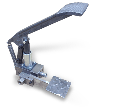
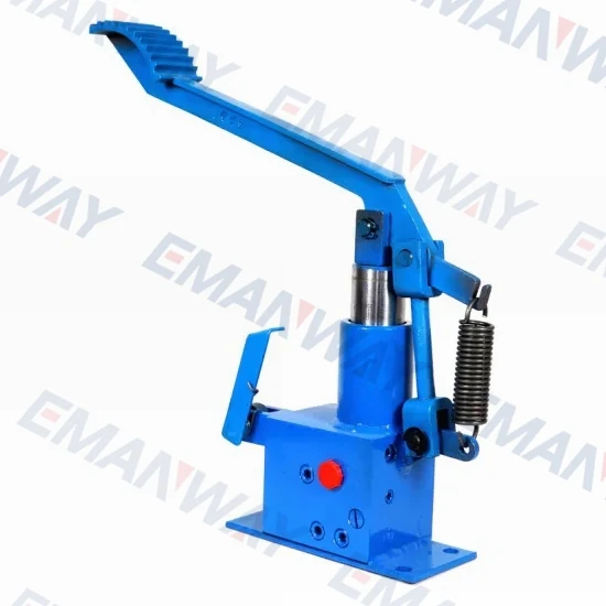
Hydraulic piston pumps are common due to their capability to enhance energy usage productivity. A hydraulic hand pump energized by a hand or foot pedal can convert a force of 4.5 pounds into a load-moving force of 100 pounds. Electric hydraulic pumps can attain pressure reaching 4,000 PSI. Because capacities vary so much, the desired usage pump must be carefully considered. Several other factors must also be considered. Standard and custom configurations of operating speeds, task-specific power sources, pump weights, and maximum fluid flows are widely available. Measurements such as rod extension length, diameter, width, and height should also be considered, particularly when a hydraulic piston pump is to be installed in place of a current hydraulic piston pump.
Hydraulic clutch pumps are mechanisms that include a clutch assembly and a pump that enables the user to apply the necessary pressure to disengage or engage the clutch mechanism. Hydraulic clutches are crafted to either link two shafts and lock them together to rotate at the same speed or detach the shafts and allow them to rotate at different speeds as needed to decelerate or shift gears.
Hydraulic pumps change hydraulic energy to mechanical energy. Hydraulic pumps are particularly designed machines utilized in commercial, industrial, and residential areas to generate useful energy from different viscous liquids pressurization. Hydraulic pumps are exceptionally simple yet effective machines for moving fluids. "Hydraulic" is actually often misspelled as "Hydralic". Hydraulic pumps depend on the energy provided by hydraulic cylinders to power different machines and mechanisms.
There are several different types of hydraulic pumps, and all hydraulic pumps can be split into two primary categories. The first category includes hydraulic pumps that function without the assistance of auxiliary power sources such as electric motors and gas. These hydraulic pump types can use the kinetic energy of a fluid to transfer it from one location to another. These pumps are commonly called ram pumps. Hydraulic hand pumps are never regarded as ram pumps, despite the fact that their operating principles are similar.
The construction, excavation, automotive manufacturing, agriculture, manufacturing, and defense contracting industries are just a few examples of operations that apply hydraulics power in normal, daily procedures. Since hydraulics usage is so prevalent, hydraulic pumps are unsurprisingly used in a wide range of machines and industries. Pumps serve the same basic function in all contexts where hydraulic machinery is used: they transport hydraulic fluid from one location to another in order to generate hydraulic energy and pressure (together with the actuators).
Elevators, automotive brakes, automotive lifts, cranes, airplane flaps, shock absorbers, log splitters, motorboat steering systems, garage jacks and other products use hydraulic pumps. The most common application of hydraulic pumps in construction sites is in big hydraulic machines and different types of "off-highway" equipment such as excavators, dumpers, diggers, and so on. Hydraulic systems are used in other settings, such as offshore work areas and factories, to power heavy machinery, cut and bend material, move heavy equipment, and so on.
Fluid’s incompressible nature in hydraulic systems allows an operator to make and apply mechanical power in an effective and efficient way. Practically all force created in a hydraulic system is applied to the intended target.
Because of the relationship between area, pressure, and force (F = P x A), modifying the force of a hydraulic system is as simple as changing the size of its components.
Hydraulic systems can transfer energy on an equal level with many mechanical and electrical systems while being significantly simpler in general. A hydraulic system, for example, can easily generate linear motion. On the contrary, most electrical and mechanical power systems need an intermediate mechanical step to convert rotational motion to linear motion.
Hydraulic systems are typically smaller than their mechanical and electrical counterparts while producing equivalents amounts of power, providing the benefit of saving physical space.
Hydraulic systems can be used in a wide range of physical settings due to their basic design (a pump attached to actuators via some kind of piping system). Hydraulic systems could also be utilized in environments where electrical systems would be impractical (for example underwater).
By removing electrical safety hazards, using hydraulic systems instead of electrical power transmission improves relative safety (for example explosions, electric shock).
The amount of power that hydraulic pumps can generate is a significant, distinct advantage. In certain cases, a hydraulic pump could generate ten times the power of an electrical counterpart. Some hydraulic pumps (for example, piston pumps) cost more than the ordinary hydraulic component. These drawbacks, however, can be mitigated by the pump"s power and efficiency. Despite their relatively high cost, piston pumps are treasured for their strength and capability to transmit very viscous fluids.
Handling hydraulic liquids is messy, and repairing leaks in a hydraulic pump can be difficult. Hydraulic liquid that leaks in hot areas may catch fire. Hydraulic lines that burst may cause serious injuries. Hydraulic liquids are corrosive as well, though some are less so than others. Hydraulic systems need frequent and intense maintenance. Parts with a high factor of precision are frequently required in systems. If the power is very high and the pipeline cannot handle the power transferred by the liquid, the high pressure received by the liquid may also cause work accidents.
Even though hydraulic systems are less complex than electrical or mechanical systems, they are still complex systems that should be handled with caution. Avoiding physical contact with hydraulic systems is an essential safety precaution when engaging with them. Even when a hydraulic machine is not in use, active liquid pressure within the system can be a hazard.
Inadequate pumps can cause mechanical failure in the place of work that can have serious and costly consequences. Although pump failure has historically been unpredictable, new diagnostic technology continues to improve on detecting methods that previously relied solely on vibration signals. Measuring discharge pressures enables manufacturers to forecast pump wear more accurately. Discharge sensors are simple to integrate into existing systems, increasing the hydraulic pump"s safety and versatility.
Hydraulic pumps are devices in hydraulic systems that move hydraulic fluid from point to point, initiating hydraulic power production. They are an important device overall in the hydraulics field, a special kind of power transmission that controls the energy which moving fluids transmit while under pressure and change into mechanical energy. Hydraulic pumps are divided into two categories namely gear pumps and piston pumps. Radial and axial piston pumps are types of piston pumps. Axial pumps produce linear motion, whereas radial pumps can produce rotary motion. The construction, excavation, automotive manufacturing, agriculture, manufacturing, and defense contracting industries are just a few examples of operations that apply hydraulics power in normal, daily procedures.

Hydraulic jack is a type of hoisting equipment widely applied to lift of vehicles or heavy goods. Existing hydraulic jack normally adopts the dynamic oil cylinder using single-post pump core and pump body hole to realize the clearance fit, which is characterized by simple structure and low technical cost. However, it is far from being able to satisfy the functional requirement for quick ascending as required by the hydraulic jack under zero or light load. As disclosed by Chinese patent ZL200620075069.1, the dual-speed vertical hydraulic jack, oil sucked by the pump core of hydraulic system of zero load or light load under low pressure can be fully pressed into the working oil chamber; whereas, partial oil is pressed into the upper chamber of the pump cylinder when the system is under high pressure. Partial oil pressed into the chamber of working oil cylinder can drive the piston assembly to hoist the loaded goods stably and quickly under the action of oil of minimal flux. As the structural technique of the pump core and pump body is so complicated, the high fabrication cost would affect the competition power of the product in international market.
In consideration of the deficiencies of aforesaid comparative technical proposal, this invention aims to put forward a type of dynamic pump of manual operation for hydraulic jack for the purpose of realizing the function of quick pump under low pressure and slow pump under high pressure for hydraulic jack in the form of relatively simple composite pump core. Meanwhile, it is also expected to provide an optional proposal for non-load pneumatic structure: make use of the high-pressure air as the driving force to press the high-pressure air into the oil chamber of the jack, so as to make the chamber of piston cylinder of the jack absorb the hydraulic oil of high flux pressed out from the oil chamber under relatively high pressure, and thus realize the quick lift of piston rod under zero or light load.
Aforesaid purposes of this invention are realized through the following technical proposal: A type of pneumatic non-load quick hydraulic dual-speed jack, including framework, base, piston rod, oil cylinder, external sleeve, connecting rod, pin, pedal rod, pump core, pump body, seal and oil return valve, has the following features: valve soleplate is fixed to the base; the lower fastness set on the pump body is sealed and fixed to the valve soleplate; the pump body is sealed and fixed to the upper fastness set and lower fastness set respectively; small piston ring on the pump cylinder is integrated with inner hole on the pump body and lower external ring of the step pump core to form movable assembly; the upper end of the fastness set and big external ring of upper fastness set aim to position the compressed spring in accommodation with spring seat; the circlip is used to position the compressed spring; the middle part of step pump core is provided with pump core step interface; a type of pneumatic non-load quick hydraulic dual-speed jack, including pneumatic valve bridge, pneumatic valve block and air source tie-in assembly, has the following features: washer, button, pneumatic valve core, compressed spring and valve core fastness set are provided inside the step hole of pneumatic valve block on the same axis.
As compared with existing technologies, this invention has the following favorable effects: axial hole of small piston ring of the pump cylinder forms a movable pair with step pump core post section through clearance fit; whereas, the external circle of the small piston ring of the pump cylinder forms a movable pair with pump body hole. Owing to the simple structural design, the pump core step interface used for conversion between quick and slow pump has high reliability, which is characterized by the excellent fabricating technique and low cost. Furthermore, the high-pressure air provided for the pneumatic valve parts of this type of jack can quickly press the hydraulic oil into the chamber of working oil cylinder to realize the quick lift of piston cylinder or rod of the jack under zero or light load, and thus improve the practicability of the product, and enhance its competitive power in the market.
1 piston rod, 2. piston cylinder; 3. oil cylinder; 4. external sleeve; 5. framework part; 6. base; 7. valve soleplate; 8. pump core step interface; 9. connecting rod; 10. pedal rod; 11. pin; 12. pin; 13. pin; 14. step pump core; 15. circlip; 16. compressed spring seat; 17. small piston ring on pump cylinder; 18. compressed spring; 19 pump body, 20 upper fastness set, 21 lower fastness set, 22 seal ring, 23 circlip, 24 seal ring, 25 seal ring, 26 pump chamber, 27 inner end surface of step hole, 28 steel ball of oil pressing unilateral valve, 29 oil way, 30 oil way, 31 oil way, 32 steel ball of oil sucking unilateral valve, 33 oil way, 34 oil way, 35 oil way, 36 oil way, 37 oil return joy stick, 38 positioning sleeve of torsion spring, 39 torsion spring, 40 oil return valve rod, 41 fastness set of oil return valve, 42 valve mandril, 43 steel ball of oil return valve, 44 compressed spring, 45 pneumatic valve core, 46 fastness set of valve core, 47 air chamber, 48 washer, 49 button, 50 muffler, 51 seal, 52 seal, 53 high-pressure air chamber, 54 air way, 55 pneumatic valve block, 56 air source tie-in assembly, 57 high-pressure regulating valve assembly, 58 seal, 59 inner cone face, 60 sealing pad, 61 screw pair, 62 elastic column pin, 63 pneumatic valve bridge, 64 pin positioning block of connecting rod, 65 sealing pad, 66 column slanting plane, 67 working oil chamber of oil cylinder, 68 compressed spring, 69 seal, 70 seal, 71 seal, 72 inner hole, 73 seal, 74 hole axial circlip, 75 flat headed screw, 76 ball bearing, 77 seal.
As indicated in attached drawing, framework part 5 is firmly fixed to base 6; oil cylinder is welded to base 6; upper and lower parts of external sleeve 4 are sealed and welded to oil cylinder 3 and base 6 respectively; piston rod 1 and piston cylinder 2 form a movable assembly through sealing; piston cylinder 2 and oil cylinder 3 form a movable assembly through sealing; pin positioning block of connecting rod 64 is firmly fixed to the valve soleplate 7; base 6 is firmly fixed to the valve soleplate 7, which subjects to the treatment for hydraulic sealing connection at the junction of corresponding oil way; firmly connect the lower fastness set 21 of pump body to the valve soleplate 7 provided with unilateral valve steel ball 32, oil way 33 and 34 as well as oil pressing unilateral valve steel ball with the help of screw pairs, and provide a sealing pad 65 at the axle of external thread end of the lower fastness set 21 to seal the high-pressure oil between lower fastness set 21 and valve soleplate 7; pump body 19 is connected to the lower fastness set 21 with screw pairs with the seal ring 77 used as the axial static seal between them; the small piston ring 17 on the pump cylinder is installed with the seal ring 22_available for dynamic sealing of hole and axis with step pump core 14; lower end of the step pump core 14 is provided with axial circlip 23; upper fastness set is connected to the upper part of the pump body 19 installed on the small piston ring 17 of the pump cylinder and its fittings with screw pairs, which uses the seal ring 25 as the static seal between the upper external circle of the pump body 19 and upper fastness set 20; clearance fit between the big external circle at the upper part of the step pump core 14 and inner hole of the upper fastness set 20 is not sealed, and the upper end of the lower fastness set 21 as well as the big external circle of upper fastness set 20 are used to position the compressed spring 18 in combination with spring seat 16 and circlip 15; the pin positioning block 64 of connecting rod is equipped with pin 11 to form revolute pair between the lower part of the connecting rod 9 and pin 11; left end of the pedal rod 10 integrates with upper part of connecting rod 9 and pin 12 to form a revolute pair, which makes use of pin 13 to realize revolute connection between the upper part of step pump core 14 and pedal rod 10; the oil pressing oil way 29 is crossly equipped with branch oil way installed with high-pressure regulating valve 57 to limit the loaded oil pressure of the hydraulic system; The upper part of the regulating valve 57 is installed with flat headed screw 75.
Operating procedures of empirical example for this invention are stated as follows: firstly, place the upper top of jack piston rod 1 under the object to be propped up; Under the action of torsion spring 39, the normal position of oil return valve rod 40 can ensure the highest position of oil return valve mandril in structural space; in other words, the steel ball 43 of oil return valve is thoroughly enclosed in the upper valve seat under the action of compressed spring 44. When the pedal rod 10 is pressed by the operator, moving mechanism would drive the step pump core 14 to move to the lower position under the combined action of connecting rod 9, pin 11, 12, and 13; when the pump core step interface 8 move downwards to contact with upper end of small piston ring 17; meanwhile, the pressure imposed on the step pump core 14 would make the small piston ring 17 of pump cylinder move downwards to the lower end of small piston ring 17 to connect with inner face of step hole; when the step pump core 14 and small piston ring of pump cylinder 17 are pressed, the hydraulic oil inside the pump chamber 26 would pressed into the working oil chamber 67 via the steel ball 28 of oil pressing unilateral valve, oil way 29, 30 and 31; the process of combined displacement of this step pump core 14 and small piston ring 17 of pump cylinder aims to supply oil at high flux for the purpose of facilitating the quick lift of piston rod 1 and piston cylinder 2; when the pressure imposed on the pedal rod 10 is released, the step pump core 14 would quickly move upwards for reverse displacement under the rebound force imposed by the compressed spring 18 to contact with the lower end of small piston ring 17 of pump cylinder at circlip 23 for the purpose of drawing the small piston ring 17 back to the highest position in the pump chamber 26. The process of combined displacement of step pump core 14 and small piston ring 17 of pump cylinder moving upwards aims to produce negative pressure inside the pump chamber 26; the hydraulic oil inside the external sleeve 4 would be pressed into the pump chamber 26 under the action of atmosphere via the oil way 34 and 33 to complete the oil absorption at high flux; when the load imposed on the jack reaches the specific value, pressure inside the oil pressing system would prop up the small piston ring 17; when the pedal rod 10 is pressed or released at this point, the relative displacement is only available between the lower external circle of step pump core 14 and inner hole of small piston ring 17, which enables the jack to press and absorb oil in circulation for the purpose of realizing the automatic conversion of hydraulic dual-speed pump through pressing.
In the hydraulic system of this empirical example, when the loaded oil pressure exceeds the pressure regulating value of high-pressure valve assembly 57, the hydraulic oil pressed out from the pump chamber 26 would automatically prop up and open the steel ball of unilateral valve of high-pressure regulating valve assembly 57 to enable the oil return to the oil chamber of external sleeve 4 via the oil way 35, 36, 33 and 34 to realize the automatic overload protection of the system.
Operating procedures of this pneumatic non-load quick lifting structure as indicated by this empirical example are stated as follows: firstly, deliver the high-pressure air to the high-pressure air chamber 53 of pneumatic valve block 55 via the air source tie-in assembly 56, and then press the button 49 to the left side to enable the pneumatic valve block to overcome the resistance imposed by the compressed spring 68 to move to the left side for the purpose of making seal 52 move away from the inner cone face 59 to facilitate the seal 51 to come into the inner hole 72 for dynamic sealing. At this point, air source inside the high-pressure air chamber 52 would be pressed into the upper position of oil inside the external sleeve 4 to maximize the air pressure inside the oil chamber quickly for the purpose of pressing the hydraulic oil into the working oil chamber 67 of oil cylinder via the oil way 34, 33, 32, 26, 28, 29, and 31; when the button 49 is released, the force imposed by the compressed spring 68 would make the pneumatic valve core 45 move to the left side, and the seal 52 would contact with inner cone face 59 for sealing to suspend the further delivery of high-pressure air into the air way 54; meanwhile, the high-pressure air inside the oil chamber of external sleeve 4 would discharge air to the air chamber 47 and muffler 50 to keep balance with atmosphere.

An aircraft hydraulic system allows for forces to be applied, multiplied, and transmitted from one location to another through an incompressible fluid medium. Hydraulics are a critical system on almost all modern aircraft. Light aircraft primarily make use of hydraulics to augment and transmit braking forces from the cockpit to the brake disk or drum. Larger, more complex aircraft may use hydraulics to actuate landing gear, flaps and control surfaces in addition to braking and nose-wheel steering.
A hydraulic system operates on the principles of Pascal’s Law and the conservation of energy to transmit a force and displacement from one point to another in the system. The basic operating principles of a hydraulic system are described below.
This means that if the pressure inside a hydraulic line is changed, e.g. the pilot depresses a brake pedal, the increased pressure due to the reduced volume in the system will be transmitted equally to all points in that system.
Pascal’s Law states that any pressure change in the system will be the same everywhere in the fluid. This means that the input and output force in the hydraulic system are related to each-other by the ratio of their respective cylinder areas.
If the area of the output cylinder is twice that of the input cylinder, then the force output will be twice the input force. Hydraulic lines therefore have the property of being a force multiplier; this is how a small jack is able to lift a large vehicle.
The principle of the conservation of energy applied to a hydraulic cylinder dictates that the system cannot do more work than is done on it. The input and output work must therefore be equal for the conservation law to apply.
Hydraulic systems work on the principle that fluid, unlike air, is virtually incompressible. This makes it a good medium to transmit and multiply forces. Incompressibility is not the only requirement for a useful hydraulic fluid; viscosity, stability, and the tendency to resist vaporization are important too.
A hydraulic fluid must have sufficient viscosity such that it aids in the lubrication and protection of the entire system, but not so great that it offers resistance to flow during operation. A typical hydraulic system is made up of cylinders, pistons, valves and pumps. If the viscosity drops too low then these components will not adequately seal, resulting in leaks in the system and poor performance.
Phosphate esters are predominantly used in larger transport category aircraft and were developed after World War Two as a response to the increase in the number of hydraulic brake fires resulting from the higher landing speeds of more modern aircraft. These fluids are colored purple and have very good fire-resistant properties.
An aircraft hydraulic system can range from very simple: an unassisted brake system on a light aircraft, to very complex. The hydraulic system on a commercial jet airliner is designed with multiple pumps, reservoirs and fluid passages, and typically drives the flight control system, brakes, high-lift devices, spoilers and nose-wheel steering.
Regardless of the complexity, all hydraulic systems comprise of a reservoir to store fluid, a pump (could be a piston actuated by a foot force) to drive the system, valves to control the direction, speed and pressure of fluid flow, a filter to remove impurities, and an actuator to apply a force on the output.
When the hydraulic system is activated, the pump pushes fluid under pressure to the high-pressure side of the actuating cylinder. This forces the piston in the cylinder to move in the direction of the applied pressure gradient. The fluid on the low-pressure side of the cylinder is forced out and returns to the reservoir via a filter to remove any impurities. Depending on the type of actuator, the applied pressure may be reversed to move the actuator in both directions.
Hydraulic systems are classified as either open-center or closed-center. In open center systems the various actuators are arranged in series such that fluid passes through each selector valve before returning to the reservoir. The fluid passes freely through each selector valve unless the valve is positioned to operate the actuator, in which case the actuator is moved as pressure builds up on the pressure side of the piston. The design of an open center system is such that the system is only under pre


 8613371530291