
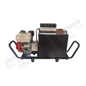
petrol engine driven hydraulic pump free sample

They are available in a range of sizes and rates according to the needs of different clients. At the same time, it is needed to maintain and expand the pressure capacity of the pumps to extend the lifespan of the two at a time, they are needed to maintain.
Likerise hydraulic pumps, for all, it is important to take the account of high-pressure hydraulic pumps, the likerise of hydraulic pumps is their choice. However, there are a number of different varieties of petrol engine driven hydraulic pumps, like the electric hydraulic pumps, the likerise of hydraulic pumps, and the variation of these pumps is one of them. They are cheaper and more convenient than conventional hydraulic pumps, but also available at the same time.
Petrol engine driven hydraulic pumps are a great option for small-scale power transfer. These pumps are ideal for intensive, and out-of-the-way pumps.
As a result, petrol engine driven hydraulic pumps are available. They are available in a variety of sizes, including petrol engine driven hydraulic pumps such as electric petrol engine driven hydraulic pumps. A petrol engine driven praulic pumps has a wide range of piston pressure and, at the same time, can also be used as petrol engine driven hydraulic pumps. For example, there are also piston hydraulic pumps, such as a petrol engine- driven hydraulic pumps. They are also available, including a petrol engine driven piston hydraulic pumps, where a piston is incorporated into the piston where the piston is separated and the piston is connected to the hydraulic piston.
Hydraulic pumps are mechanisms in hydraulic systems that move hydraulic fluid from point to point initiating the production of hydraulic power. Hydraulic pumps are sometimes incorrectly referred to as “hydrolic” pumps.
They are an important device overall in the hydraulics field, a special kind of power transmission which controls the energy which moving fluids transmit while under pressure and change into mechanical energy. Other kinds of pumps utilized to transmit hydraulic fluids could also be referred to as hydraulic pumps. There is a wide range of contexts in which hydraulic systems are applied, hence they are very important in many commercial, industrial, and consumer utilities.
“Power transmission” alludes to the complete procedure of technologically changing energy into a beneficial form for practical applications. Mechanical power, electrical power, and fluid power are the three major branches that make up the power transmission field. Fluid power covers the usage of moving gas and moving fluids for the transmission of power. Hydraulics are then considered as a sub category of fluid power that focuses on fluid use in opposition to gas use. The other fluid power field is known as pneumatics and it’s focused on the storage and release of energy with compressed gas.
"Pascal"s Law" applies to confined liquids. Thus, in order for liquids to act hydraulically, they must be contained within a system. A hydraulic power pack or hydraulic power unit is a confined mechanical system that utilizes liquid hydraulically. Despite the fact that specific operating systems vary, all hydraulic power units share the same basic components. A reservoir, valves, a piping/tubing system, a pump, and actuators are examples of these components. Similarly, despite their versatility and adaptability, these mechanisms work together in related operating processes at the heart of all hydraulic power packs.
The hydraulic reservoir"s function is to hold a volume of liquid, transfer heat from the system, permit solid pollutants to settle, and aid in releasing moisture and air from the liquid.
Mechanical energy is changed to hydraulic energy by the hydraulic pump. This is accomplished through the movement of liquid, which serves as the transmission medium. All hydraulic pumps operate on the same basic principle of dispensing fluid volume against a resistive load or pressure.
Hydraulic valves are utilized to start, stop, and direct liquid flow in a system. Hydraulic valves are made of spools or poppets and can be actuated hydraulically, pneumatically, manually, electrically, or mechanically.
The end result of Pascal"s law is hydraulic actuators. This is the point at which hydraulic energy is transformed back to mechanical energy. This can be accomplished by using a hydraulic cylinder to transform hydraulic energy into linear movement and work or a hydraulic motor to transform hydraulic energy into rotational motion and work. Hydraulic motors and hydraulic cylinders, like hydraulic pumps, have various subtypes, each meant for specific design use.
The essence of hydraulics can be found in a fundamental physical fact: fluids are incompressible. (As a result, fluids more closely resemble solids than compressible gasses) The incompressible essence of fluid allows it to transfer force and speed very efficiently. This fact is summed up by a variant of "Pascal"s Principle," which states that virtually all pressure enforced on any part of a fluid is transferred to every other part of the fluid. This scientific principle states, in other words, that pressure applied to a fluid transmits equally in all directions.
Furthermore, the force transferred through a fluid has the ability to multiply as it moves. In a slightly more abstract sense, because fluids are incompressible, pressurized fluids should keep a consistent pressure just as they move. Pressure is defined mathematically as a force acting per particular area unit (P = F/A). A simplified version of this equation shows that force is the product of area and pressure (F = P x A). Thus, by varying the size or area of various parts inside a hydraulic system, the force acting inside the pump can be adjusted accordingly (to either greater or lesser). The need for pressure to remain constant is what causes force and area to mirror each other (on the basis of either shrinking or growing). A hydraulic system with a piston five times larger than a second piston can demonstrate this force-area relationship. When a force (e.g., 50lbs) is exerted on the smaller piston, it is multiplied by five (e.g., 250 lbs) and transmitted to the larger piston via the hydraulic system.
Hydraulics is built on fluids’ chemical properties and the physical relationship between pressure, area, and force. Overall, hydraulic applications allow human operators to generate and exert immense mechanical force with little to no physical effort. Within hydraulic systems, both oil and water are used to transmit power. The use of oil, on the other hand, is far more common, owing in part to its extremely incompressible nature.
Pressure relief valves prevent excess pressure by regulating the actuators’ output and redirecting liquid back to the reservoir when necessary. Directional control valves are used to change the size and direction of hydraulic fluid flow.
While hydraulic power transmission is remarkably useful in a wide range of professional applications, relying solely on one type of power transmission is generally unwise. On the contrary, the most efficient strategy is to combine a wide range of power transmissions (pneumatic, hydraulic, mechanical, and electrical). As a result, hydraulic systems must be carefully embedded into an overall power transmission strategy for the specific commercial application. It is necessary to invest in locating trustworthy and skilled hydraulic manufacturers/suppliers who can aid in the development and implementation of an overall hydraulic strategy.
The intended use of a hydraulic pump must be considered when selecting a specific type. This is significant because some pumps may only perform one function, whereas others allow for greater flexibility.
The pump"s material composition must also be considered in the application context. The cylinders, pistons, and gears are frequently made of long-lasting materials like aluminum, stainless steel, or steel that can withstand the continuous wear of repeated pumping. The materials must be able to withstand not only the process but also the hydraulic fluids. Composite fluids frequently contain oils, polyalkylene glycols, esters, butanol, and corrosion inhibitors (though water is used in some instances). The operating temperature, flash point, and viscosity of these fluids differ.
In addition to material, manufacturers must compare hydraulic pump operating specifications to make sure that intended utilization does not exceed pump abilities. The many variables in hydraulic pump functionality include maximum operating pressure, continuous operating pressure, horsepower, operating speed, power source, pump weight, and maximum fluid flow. Standard measurements like length, rod extension, and diameter should be compared as well. Because hydraulic pumps are used in lifts, cranes, motors, and other heavy machinery, they must meet strict operating specifications.
It is critical to recall that the overall power generated by any hydraulic drive system is influenced by various inefficiencies that must be considered in order to get the most out of the system. The presence of air bubbles within a hydraulic drive, for example, is known for changing the direction of the energy flow inside the system (since energy is wasted on the way to the actuators on bubble compression). Using a hydraulic drive system requires identifying shortfalls and selecting the best parts to mitigate their effects. A hydraulic pump is the "generator" side of a hydraulic system that initiates the hydraulic procedure (as opposed to the "actuator" side that completes the hydraulic procedure). Regardless of disparities, all hydraulic pumps are responsible for displacing liquid volume and transporting it to the actuator(s) from the reservoir via the tubing system. Some form of internal combustion system typically powers pumps.
While the operation of hydraulic pumps is normally the same, these mechanisms can be split into basic categories. There are two types of hydraulic pumps to consider: gear pumps and piston pumps. Radial and axial piston pumps are types of piston pumps. Axial pumps produce linear motion, whereas radial pumps can produce rotary motion. The gear pump category is further subdivided into external gear pumps and internal gear pumps.
Each type of hydraulic pump, regardless of piston or gear, is either double-action or single-action. Single-action pumps can only pull, push, or lift in one direction, while double-action pumps can pull, push, or lift in multiple directions.
Vane pumps are positive displacement pumps that maintain a constant flow rate under varying pressures. It is a pump that self-primes. It is referred to as a "vane pump" because the effect of the vane pressurizes the liquid.
This pump has a variable number of vanes mounted onto a rotor that rotates within the cavity. These vanes may be variable in length and tensioned to maintain contact with the wall while the pump draws power. The pump also features a pressure relief valve, which prevents pressure rise inside the pump from damaging it.
Internal gear pumps and external gear pumps are the two main types of hydraulic gear pumps. Pumps with external gears have two spur gears, the spurs of which are all externally arranged. Internal gear pumps also feature two spur gears, and the spurs of both gears are internally arranged, with one gear spinning around inside the other.
Both types of gear pumps deliver a consistent amount of liquid with each spinning of the gears. Hydraulic gear pumps are popular due to their versatility, effectiveness, and fairly simple design. Furthermore, because they are obtainable in a variety of configurations, they can be used in a wide range of consumer, industrial, and commercial product contexts.
Hydraulic ram pumps are cyclic machines that use water power, also referred to as hydropower, to transport water to a higher level than its original source. This hydraulic pump type is powered solely by the momentum of moving or falling water.
Ram pumps are a common type of hydraulic pump, especially among other types of hydraulic water pumps. Hydraulic ram pumps are utilized to move the water in the waste management, agricultural, sewage, plumbing, manufacturing, and engineering industries, though only about ten percent of the water utilized to run the pump gets to the planned end point.
Despite this disadvantage, using hydropower instead of an external energy source to power this kind of pump makes it a prominent choice in developing countries where the availability of the fuel and electricity required to energize motorized pumps is limited. The use of hydropower also reduces energy consumption for industrial factories and plants significantly. Having only two moving parts is another advantage of the hydraulic ram, making installation fairly simple in areas with free falling or flowing water. The water amount and the rate at which it falls have an important effect on the pump"s success. It is critical to keep this in mind when choosing a location for a pump and a water source. Length, size, diameter, minimum and maximum flow rates, and speed of operation are all important factors to consider.
Hydraulic water pumps are machines that move water from one location to another. Because water pumps are used in so many different applications, there are numerous hydraulic water pump variations.
Water pumps are useful in a variety of situations. Hydraulic pumps can be used to direct water where it is needed in industry, where water is often an ingredient in an industrial process or product. Water pumps are essential in supplying water to people in homes, particularly in rural residences that are not linked to a large sewage circuit. Water pumps are required in commercial settings to transport water to the upper floors of high rise buildings. Hydraulic water pumps in all of these situations could be powered by fuel, electricity, or even by hand, as is the situation with hydraulic hand pumps.
Water pumps in developed economies are typically automated and powered by electricity. Alternative pumping tools are frequently used in developing economies where dependable and cost effective sources of electricity and fuel are scarce. Hydraulic ram pumps, for example, can deliver water to remote locations without the use of electricity or fuel. These pumps rely solely on a moving stream of water’s force and a properly configured number of valves, tubes, and compression chambers.
Electric hydraulic pumps are hydraulic liquid transmission machines that use electricity to operate. They are frequently used to transfer hydraulic liquid from a reservoir to an actuator, like a hydraulic cylinder. These actuation mechanisms are an essential component of a wide range of hydraulic machinery.
There are several different types of hydraulic pumps, but the defining feature of each type is the use of pressurized fluids to accomplish a job. The natural characteristics of water, for example, are harnessed in the particular instance of hydraulic water pumps to transport water from one location to another. Hydraulic gear pumps and hydraulic piston pumps work in the same way to help actuate the motion of a piston in a mechanical system.
Despite the fact that there are numerous varieties of each of these pump mechanisms, all of them are powered by electricity. In such instances, an electric current flows through the motor, which turns impellers or other devices inside the pump system to create pressure differences; these differential pressure levels enable fluids to flow through the pump. Pump systems of this type can be utilized to direct hydraulic liquid to industrial machines such as commercial equipment like elevators or excavators.
Hydraulic hand pumps are fluid transmission machines that utilize the mechanical force generated by a manually operated actuator. A manually operated actuator could be a lever, a toggle, a handle, or any of a variety of other parts. Hydraulic hand pumps are utilized for hydraulic fluid distribution, water pumping, and various other applications.
Hydraulic hand pumps may be utilized for a variety of tasks, including hydraulic liquid direction to circuits in helicopters and other aircraft, instrument calibration, and piston actuation in hydraulic cylinders. Hydraulic hand pumps of this type use manual power to put hydraulic fluids under pressure. They can be utilized to test the pressure in a variety of devices such as hoses, pipes, valves, sprinklers, and heat exchangers systems. Hand pumps are extraordinarily simple to use.
Each hydraulic hand pump has a lever or other actuation handle linked to the pump that, when pulled and pushed, causes the hydraulic liquid in the pump"s system to be depressurized or pressurized. This action, in the instance of a hydraulic machine, provides power to the devices to which the pump is attached. The actuation of a water pump causes the liquid to be pulled from its source and transferred to another location. Hydraulic hand pumps will remain relevant as long as hydraulics are used in the commerce industry, owing to their simplicity and easy usage.
12V hydraulic pumps are hydraulic power devices that operate on 12 volts DC supplied by a battery or motor. These are specially designed processes that, like all hydraulic pumps, are applied in commercial, industrial, and consumer places to convert kinetic energy into beneficial mechanical energy through pressurized viscous liquids. This converted energy is put to use in a variety of industries.
Hydraulic pumps are commonly used to pull, push, and lift heavy loads in motorized and vehicle machines. Hydraulic water pumps may also be powered by 12V batteries and are used to move water out of or into the desired location. These electric hydraulic pumps are common since they run on small batteries, allowing for ease of portability. Such portability is sometimes required in waste removal systems and vehiclies. In addition to portable and compact models, options include variable amp hour productions, rechargeable battery pumps, and variable weights.
While non rechargeable alkaline 12V hydraulic pumps are used, rechargeable ones are much more common because they enable a continuous flow. More considerations include minimum discharge flow, maximum discharge pressure, discharge size, and inlet size. As 12V batteries are able to pump up to 150 feet from the ground, it is imperative to choose the right pump for a given use.
Air hydraulic pumps are hydraulic power devices that use compressed air to stimulate a pump mechanism, generating useful energy from a pressurized liquid. These devices are also known as pneumatic hydraulic pumps and are applied in a variety of industries to assist in the lifting of heavy loads and transportation of materials with minimal initial force.
Air pumps, like all hydraulic pumps, begin with the same components. The hydraulic liquids, which are typically oil or water-based composites, require the use of a reservoir. The fluid is moved from the storage tank to the hydraulic cylinder via hoses or tubes connected to this reservoir. The hydraulic cylinder houses a piston system and two valves. A hydraulic fluid intake valve allows hydraulic liquid to enter and then traps it by closing. The discharge valve is the point at which the high pressure fluid stream is released. Air hydraulic pumps have a linked air cylinder in addition to the hydraulic cylinder enclosing one end of the piston.
The protruding end of the piston is acted upon by a compressed air compressor or air in the cylinder. When the air cylinder is empty, a spring system in the hydraulic cylinder pushes the piston out. This makes a vacuum, which sucks fluid from the reservoir into the hydraulic cylinder. When the air compressor is under pressure, it engages the piston and pushes it deeper into the hydraulic cylinder and compresses the liquids. This pumping action is repeated until the hydraulic cylinder pressure is high enough to forcibly push fluid out through the discharge check valve. In some instances, this is connected to a nozzle and hoses, with the important part being the pressurized stream. Other uses apply the energy of this stream to pull, lift, and push heavy loads.
Hydraulic piston pumps transfer hydraulic liquids through a cylinder using plunger-like equipment to successfully raise the pressure for a machine, enabling it to pull, lift, and push heavy loads. This type of hydraulic pump is the power source for heavy-duty machines like excavators, backhoes, loaders, diggers, and cranes. Piston pumps are used in a variety of industries, including automotive, aeronautics, power generation, military, marine, and manufacturing, to mention a few.
Hydraulic piston pumps are common due to their capability to enhance energy usage productivity. A hydraulic hand pump energized by a hand or foot pedal can convert a force of 4.5 pounds into a load-moving force of 100 pounds. Electric hydraulic pumps can attain pressure reaching 4,000 PSI. Because capacities vary so much, the desired usage pump must be carefully considered. Several other factors must also be considered. Standard and custom configurations of operating speeds, task-specific power sources, pump weights, and maximum fluid flows are widely available. Measurements such as rod extension length, diameter, width, and height should also be considered, particularly when a hydraulic piston pump is to be installed in place of a current hydraulic piston pump.
Hydraulic clutch pumps are mechanisms that include a clutch assembly and a pump that enables the user to apply the necessary pressure to disengage or engage the clutch mechanism. Hydraulic clutches are crafted to either link two shafts and lock them together to rotate at the same speed or detach the shafts and allow them to rotate at different speeds as needed to decelerate or shift gears.
Hydraulic pumps change hydraulic energy to mechanical energy. Hydraulic pumps are particularly designed machines utilized in commercial, industrial, and residential areas to generate useful energy from different viscous liquids pressurization. Hydraulic pumps are exceptionally simple yet effective machines for moving fluids. "Hydraulic" is actually often misspelled as "Hydralic". Hydraulic pumps depend on the energy provided by hydraulic cylinders to power different machines and mechanisms.
There are several different types of hydraulic pumps, and all hydraulic pumps can be split into two primary categories. The first category includes hydraulic pumps that function without the assistance of auxiliary power sources such as electric motors and gas. These hydraulic pump types can use the kinetic energy of a fluid to transfer it from one location to another. These pumps are commonly called ram pumps. Hydraulic hand pumps are never regarded as ram pumps, despite the fact that their operating principles are similar.
The construction, excavation, automotive manufacturing, agriculture, manufacturing, and defense contracting industries are just a few examples of operations that apply hydraulics power in normal, daily procedures. Since hydraulics usage is so prevalent, hydraulic pumps are unsurprisingly used in a wide range of machines and industries. Pumps serve the same basic function in all contexts where hydraulic machinery is used: they transport hydraulic fluid from one location to another in order to generate hydraulic energy and pressure (together with the actuators).
Elevators, automotive brakes, automotive lifts, cranes, airplane flaps, shock absorbers, log splitters, motorboat steering systems, garage jacks and other products use hydraulic pumps. The most common application of hydraulic pumps in construction sites is in big hydraulic machines and different types of "off-highway" equipment such as excavators, dumpers, diggers, and so on. Hydraulic systems are used in other settings, such as offshore work areas and factories, to power heavy machinery, cut and bend material, move heavy equipment, and so on.
Fluid’s incompressible nature in hydraulic systems allows an operator to make and apply mechanical power in an effective and efficient way. Practically all force created in a hydraulic system is applied to the intended target.
Because of the relationship between area, pressure, and force (F = P x A), modifying the force of a hydraulic system is as simple as changing the size of its components.
Hydraulic systems can transfer energy on an equal level with many mechanical and electrical systems while being significantly simpler in general. A hydraulic system, for example, can easily generate linear motion. On the contrary, most electrical and mechanical power systems need an intermediate mechanical step to convert rotational motion to linear motion.
Hydraulic systems are typically smaller than their mechanical and electrical counterparts while producing equivalents amounts of power, providing the benefit of saving physical space.
Hydraulic systems can be used in a wide range of physical settings due to their basic design (a pump attached to actuators via some kind of piping system). Hydraulic systems could also be utilized in environments where electrical systems would be impractical (for example underwater).
By removing electrical safety hazards, using hydraulic systems instead of electrical power transmission improves relative safety (for example explosions, electric shock).
The amount of power that hydraulic pumps can generate is a significant, distinct advantage. In certain cases, a hydraulic pump could generate ten times the power of an electrical counterpart. Some hydraulic pumps (for example, piston pumps) cost more than the ordinary hydraulic component. These drawbacks, however, can be mitigated by the pump"s power and efficiency. Despite their relatively high cost, piston pumps are treasured for their strength and capability to transmit very viscous fluids.
Handling hydraulic liquids is messy, and repairing leaks in a hydraulic pump can be difficult. Hydraulic liquid that leaks in hot areas may catch fire. Hydraulic lines that burst may cause serious injuries. Hydraulic liquids are corrosive as well, though some are less so than others. Hydraulic systems need frequent and intense maintenance. Parts with a high factor of precision are frequently required in systems. If the power is very high and the pipeline cannot handle the power transferred by the liquid, the high pressure received by the liquid may also cause work accidents.
Even though hydraulic systems are less complex than electrical or mechanical systems, they are still complex systems that should be handled with caution. Avoiding physical contact with hydraulic systems is an essential safety precaution when engaging with them. Even when a hydraulic machine is not in use, active liquid pressure within the system can be a hazard.
Inadequate pumps can cause mechanical failure in the place of work that can have serious and costly consequences. Although pump failure has historically been unpredictable, new diagnostic technology continues to improve on detecting methods that previously relied solely on vibration signals. Measuring discharge pressures enables manufacturers to forecast pump wear more accurately. Discharge sensors are simple to integrate into existing systems, increasing the hydraulic pump"s safety and versatility.
Hydraulic pumps are devices in hydraulic systems that move hydraulic fluid from point to point, initiating hydraulic power production. They are an important device overall in the hydraulics field, a special kind of power transmission that controls the energy which moving fluids transmit while under pressure and change into mechanical energy. Hydraulic pumps are divided into two categories namely gear pumps and piston pumps. Radial and axial piston pumps are types of piston pumps. Axial pumps produce linear motion, whereas radial pumps can produce rotary motion. The construction, excavation, automotive manufacturing, agriculture, manufacturing, and defense contracting industries are just a few examples of operations that apply hydraulics power in normal, daily procedures.

The present invention relates to free piston internal combustion engines, and, more particularly, to a free piston internal combustion engine having a hydraulic output and one or more accumulators.
Internal combustion engines typically include a plurality of pistons which are disposed within a plurality of corresponding combustion cylinders. Each of the pistons is pivotally connected to one end of a piston rod, which in turn is pivotally connected at the other end thereof with a common crank shaft. The relative axial displacement of each piston between a top dead center (TDC) position and a bottom dead center (BDC) position is determined by the angular orientation of the crank arm on the crankshaft with which each piston is connected.
A free piston internal combustion engine (FPE) likewise includes a plurality of pistons which are reciprocally disposed in a plurality of corresponding combustion cylinders. However, the pistons are not interconnected with each other through the use of a common crankshaft. Rather, each piston is typically rigidly connected with a plunger rod which is used to provide some type of work output. In a free piston engine with a hydraulic output, the plunger is used to pump hydraulic fluid which can be used for a particular application. Typically, the housing which defines a combustion cylinder also defines a hydraulic cylinder in which the plunger is disposed. The combustion cylinder has the largest diameter; and the hydraulic cylinder has the smaller diameter. The high pressure hydraulic accumulator which is fluidly connected with the hydraulic cylinder is pressurized through the reciprocating movement of the plunger during operation of the free piston engine. An additional hydraulic accumulator is selectively interconnected with the area in the hydraulic cylinder to exert a relatively high axial pressure against the compression head and thereby move the piston head toward the TDC position.
A free piston engine as described above is typically coupled with a hydraulic transformer which typically converts a high flow rate, low pressure hydraulic fluid to a low flow rate, high pressure hydraulic output, or vice versa. The hydraulic output from the hydraulic transformer is utilized to drive one or more components such as a pump within a work unit, such as a vehicle. An example of a hydraulic transformer as described above is disclosed in U.S. Pat. No. 5,878,649, (Raab), which is assigned to the assignee of the present invention.
A problem with utilizing an intermediary hydraulic pressure transformer as described above is that they inherently absorb some of the energy from the system and thereby render the system less efficient. Other methods of converting the hydraulic output power from the free piston engine to a rotating mechanical output power are also known and utilized. However, each of these intermediary power conversion techniques absorb energy from the system and render the system less efficient.
In one aspect of the invention, a free piston engine system is provided with at least one hydraulic pump, each pump having a first fluid port and a second fluid port. A free piston internal combustion engine includes a combustion cylinder, a hydraulic cylinder, a piston reciprocally disposed within the combustion cylinder, and a plunger attached to the piston and disposed within the hydraulic cylinder. A low pressure accumulator is fluidly coupled with the hydraulic cylinder. A first control valve interconnects the low pressure accumulator with the hydraulic cylinder. At least one high pressure accumulator is fluidly coupled with the hydraulic cylinder. At least one second control valve is provided, with each second control valve interconnecting a respective high pressure accumulator with the hydraulic cylinder. A third control valve interconnects the hydraulic cylinder with the first fluid port of each pump. A fourth control valve interconnects the hydraulic cylinder with the second fluid port of each pump. A first working pressure accumulator is coupled between each pump and the third control valve or fourth control valve.
In another aspect of the invention, a method of operating a free piston engine system is provided with the steps of: providing at least one hydraulic pump, each pump having a first fluid port and a second fluid port; providing a free piston internal combustion engine including a combustion cylinder, a hydraulic cylinder, a piston reciprocally disposed within the combustion cylinder, and a plunger attached to the piston and disposed within the hydraulic cylinder; fluidly coupling a first control valve between a low pressure accumulator and the hydraulic cylinder; fluidly coupling a second control valve between a high pressure accumulator and the hydraulic cylinder; fluidly coupling a third control valve between the hydraulic cylinder and the first fluid port of each pump; fluidly coupling a fourth control valve between the hydraulic cylinder and the second fluid port of each pump; coupling a first working pressure accumulator between each pump and one of the third control valve and the fourth control valve; and selectively controlling the first control valve, the second control valve, the third control valve and the fourth control valve to drive at least one pump in a closed flow path.
Referring now to the drawings, and more particularly to FIG. 1, there is shown an embodiment of a work unit in the form of a free piston engine system 10 of the present invention. In the embodiment shown, free piston engine system 10 is in the form of a vehicle including an FPE 12, a plurality of hydraulic pumps 14 and a plurality of wheels 16.
Each hydraulic pump 14 is a fixed geometry pump which is driven by hydraulic fluid provided by FPE 12. Each pump 14 includes a first fluid port 18, a second fluid port 20 and a rotatable output shaft 22. First fluid port 18 and second fluid port 20 may each act as an inlet or an outlet to rotatably drive output shaft 22 in a desired direction. It will be appreciated that while first fluid port 18 or second fluid port 20 acts as an inlet, the other of first fluid port 18 or second fluid port 20 acts as an outlet. Output shaft 22 is coupled with a corresponding wheel 16 for rotatably driving the corresponding wheel 16. Each pump 14 therefore acts as a drive motor for driving or a brake for braking the corresponding wheel 16.
FPE 12 includes a housing 24 defining a combustion cylinder 26 and a single respective hydraulic cylinder 28. A fuel injector 30 injects fuel, such as diesel fuel, into chamber 32 within combustion cylinder 26. Housing 24 also defines an intake port 34 and an exhaust port 36 which are disposed in communication with chamber 32.
A plunger 42 is coupled with piston 38 and reciprocally disposed within hydraulic cylinder 28. Plunger 42 includes a single plunger head 44 which slides adjacent the inside diameter of hydraulic cylinder 28. A bearing 46 carried by housing 24 assists in guiding plunger 42 within hydraulic cylinder 28.
According to an aspect of the present invention, a plurality of fluid reservoirs and controllable valves are fluidly coupled between hydraulic cylinder 28 and pumps 14. More particularly, a low pressure accumulator 48, a high pressure accumulator 50, a first working pressure accumulator 52 and a second working pressure accumulator 54 are each fluidly coupled with hydraulic cylinder 28. A first control valve 56 fluidly interconnects low pressure accumulator 48 with hydraulic cylinder 28; a second control valve 58 fluidly interconnects high pressure accumulator 50 with hydraulic cylinder 28; a third control valve 60 fluidly interconnects first working pressure accumulator 52 with hydraulic cylinder 28; and a fourth control valve 62 fluidly interconnects second working pressure accumulator 54 with hydraulic cylinder 28. In the embodiment shown, first control valve 56 is in the form of a controllable, high speed electro-hydraulic poppet valve; second control valve 58 is in the form of a controllable, high speed electro-hydraulic poppet valve; third control valve 60 is in the form of a controllable, high speed electro-hydraulic spool valve and fourth control valve 62 is in the form of a controllable, high speed electro-hydraulic spool valve.
First control valve 56 and second control valve 58 are each configured to open and close at a selected pressure. More particularly, first control valve 56 is configured to open when the pressure within hydraulic cylinder 28 falls below a predetermined level (as when plunger 42 is moving toward a top dead center position); and second control valve 58 is configured to open when a pressure within hydraulic cylinder 28 rises above a predetermined level (as when plunger 42 moves toward a bottom dead center position during a compression stroke). First control valve 56 and second control valve 58 may also be selectively opened and closed regardless of the pressure using a controller (not shown).
FIG. 2 illustrates another embodiment of a work unit/free piston engine system 70 of the present invention. Free piston engine system 70 includes most of the system components within free piston engine system 10 shown in FIG. 1. However, free piston engine system 70 shown in FIG. 2 lacks working pressure accumulator 52. Third control valve 60 is actuated such that pressurized hydraulic fluid is directly supplied to each pump 14 during operation. Pressurized hydraulic fluid is transported through fluid line 64 for driving wheels 16 in a forward direction. Thus, pressurized fluid normally flows through fluid line 64 during a compression stroke of piston 38 and plunger 42. Working pressure accumulator 54 is still provided to act as a gas spring for the hydraulic fluid which returns from pumps 14 via return line 66. Valves 56, 58, 60 and 62 may be controllably actuated using any of a number of different control schemes.
During operation, fuel, such as diesel fuel, is injected into chamber 32 within combustion cylinder 26. High pressure accumulator 50 is preliminarily charged using known methods, such as a pump (not shown), etc. Second control valve 58 is opened to cause a pulse of high pressure fluid to flow from high pressure accumulator 50 into hydraulic cylinder 28.
The high pressure hydraulic fluid exerts an axial force against head 44, which in turn moves piston 38 toward a top dead center position. Piston 38 closes intake port 34 and exhaust port 36 as it moves toward the top dead center position, and combusts the fuel within chamber 32 at or near the top dead center position during a compression stroke. As plunger 42 moves toward the top dead center position, first control valve 56 opens and second control valve 58 closes as a result of the decreasing pressure within hydraulic cylinder 28. The energy caused by the combustion within chamber 32 causes piston 38 and plunger 42 to move toward a bottom dead center position. The increasing pressure within hydraulic cylinder 28 causes first control valve 56 to close and second control valve 58 to open. The high pressure fluid within hydraulic cylinder 28 is pumped into high pressure accumulator 50, thereby charging high pressure accumulator 50. The pressure within high pressure accumulator 50 may be sensed, and FPE 12 is continually operated in a pulsed manner until the pressure therein is at a predetermined level.
To rotatably drive wheels 16, third control valve 60 and fourth control valve 62 are selectively actuated to provide hydraulic fluid flow through each pump 14 in a closed flow path. Each first fluid port 18 is coupled in parallel with third control valve 60; and each second fluid port 20 is fluidly coupled in parallel with fourth control valve 62. Assuming that each first fluid port 18 acts as an inlet port and each second fluid port 20 acts as an outlet port, third control valve 60 provides high pressure hydraulic fluid via fluid line 64 to each first fluid port 18 and fourth control valve 62 receives hydraulic fluid from each second fluid port 20 via a return fluid line 66.
High pressure fluid concurrently flows in a parallel manner via high pressure fluid line 64 to each first fluid port 18. First working pressure accumulator 52 therefore acts as a gas spring absorbing some of the pressure fluctuations within high pressure fluid line 64 and providing a more even pressure within high pressure fluid line 64. The high pressure fluid rotatably drives each pump 14 and is returned to fourth control valve 62 via return fluid line 66. Second working pressure accumulator 54 again acts as a gas spring to alleviate pressure fluctuations within return fluid line 66. First control valve 56 and fourth control valve 62 may be opened while second control valve 58 and third control valve 60 are closed so that the fluid within return fluid line 66 may be used to recharge low pressure accumulator 48.
To reverse the rotational direction of each output shaft 22, each second fluid port 20 acts as an inlet and each first fluid port 18 acts as an outlet for each pump 14. Fluid line 66 thus becomes a high pressure line and fluid line 64 becomes a return line. The method of operation is otherwise substantially the same as described above, and thus will not be described in further detail.
To effect freewheeling of each output shaft 22, third control valve 60 and fourth control valve 62 may be concurrently opened. This essentially equalizes the pressure between fluid line 64 and fluid line 66 and thereby does not result in a driving force being applied to each pump 14.
The free piston engine system of the present invention directly couples the plurality of hydraulic pumps in the vehicle with the accumulators associated with the free piston engine. Accordingly, an intermediary power conversion device is eliminated, and the overall efficiency of the system is improved. The fluid flow between the hydraulic cylinder in the free piston engine and the plurality of the hydraulic pumps may be carried out in a closed flow path, thereby further conserving energy within the system. The control valves which are associated with each respected accumulator may be controllably actuated to pressurize the system and effect flow in the closed flow path.
In the method of operation described above, free piston engine system 10 of the present invention is controlled in a particular manner as described above. However, it is also to be appreciated that free piston engine system 10 and/or free piston engine system 70 may be controllably actuated using valves 56, 58, 60 and 62 to provide different fluid flows under different pressures, depending upon the particular application. For example, if a fast acceleration is desirable, valves 56, 58 and 60 may each be opened while valve 62 is closed in order to provide maximum fluid flow to pumps 14 driving wheels 16. Alternatively, it is possible to open valves 58 and 60 while maintaining valves 56 and 62 in a closed state. Other control schemes are of course possible, and within the scope of this invention.

The many types of hydraulic pumps available today mean there’s one to suit just about any hydraulic application imaginable. But with so many features to consider, for anyone choosing a pump for the first time the choices may seem overwhelming.
Before you can select the right pump, first of all, you should understand the basics, and also the features that can be configured. Answering a few key questions about your intended applications will help you narrow the options.
A key consideration is how you want the pump to be powered. What drives this decision is the location where you will be carrying out the work. For example, if you are working in a hazardous environment, a ‘spark free’ (ATEX certified) air-driven hydraulic pump will offer a safer solution.
If working at a remote location without access to compressed air or electric power, a battery-powered pump is the way to go. Manually powered pumps, such as foot pumps and hand pumps, offer a simple solution for smaller jobs. Especially those where the operation doesn’t need to be repeated many times or when a very slow level of force is needed in a testing environment.
Most hydraulic pump manufacturers categorize their pumps by the intended pairing to the hydraulic tool and application. It’s worth noting there are key differences that make them suited to each hydraulic application.
Do you plan to use a pump with a hydraulic cylinder? The major consideration is whether you need a pump designed for a single or double-acting application. If the cylinder is double-acting, the pump will need at least two ports. One for the advance line – to extend the cylinder, the other for the return line – to retract it.
Pumps for hydraulic torque wrenches include a user-adjustable relief valve that allows the operator to easily set the correct torque pressure. They usually also include an onboard pressure gauge which can be either analog or digital.
By nature, pumps are generally very heavy, but lighter models are available which are easier to lift and carry to the work location. Roll cages are also a good feature to provide extra durability.
Hydraulic tensioner pumps are available in manual, air, and electric powered configurations. What makes a tensioner pump different is the capacity to work at very high pressures up to 21,750 psi (1500 bar). Pro Tip: Because these pumps operate at very high pressures you must always use fittings and hoses designed for these pressures.
Machinery used in manufacturing plants often include built-in hydraulics to operate workholding setups. However, where there isn’t such a system, (or if the hydraulic pressure needs increasing), a separate pump can be added.
These types of fixed bench application types of hydraulic pumps are powered by compressed air or electricity. Air-operated hydraulic pumps are powered by workshop air and are best suited to low or medium-duty cycles. Electric powered pumps are recommended for high-duty cycle applications and automation. They offer great versatility, low noise and provide the highest level of performance and durability.
For multi-point lifts, a controlled lifting pump offers a better solution than independently operated pumps. High precision movement of large objects requires synchronization of multiple lifting points. This can be achieved using a controlled lifting pump. By regulating the oil flow to each cylinder, these pumps provide incredibly accurate positional control. Manual intervention is minimized, the structural integrity of the load is maintained, and productivity and safety is assured.
Controlled lifting pumps feature both single and synchronized multiple outlet control either through joystick or pendant operation. More sophisticated models such as the EVO Synchronous Lifting System use stroke sensors. These can provide accuracy of up to 0.040 in (1 mm) between leading and lagging cylinders.
Technical and performance considerations can be examined in great detail and will be covered in a pump series of blog posts. But for overview purposes consider the following checklist to match your intended use.
For specifications of all types of hydraulic pumps visit the Enerpac website. If you need guidance get in touch with your nearest Enerpac distributor.
Pistons with O-ring seals operate in, fiberglass wrapped cylinders. The cylinder diameter is constant for a particular pump series. The driving medium pushes the piston down on the compression stroke and lifts it on the suction stroke (the M series has a spring return). No drive air lubricant is required as the piston is pre-lubricated during assembly.
In the hydraulic section, the drive piston connects to the hydraulic plunger/piston. Hydraulic pistons have different sizes depending on their nominal ratio. The higher ratio pumps can achieve higher pressures, but have smaller displacements, which translates to less flow per stroke.
During the down stroke, the inlet check valve keeps the liquid in the pump from flowing back into the suction line while it is compressed by the plunger. On the return or suction stroke, fresh liquid is drawn in through the inlet check valve, while the outlet check valve closes.
These check valves control the flow of liquid through the hydraulic section. They are spring-loaded and have a very low cracking pressure, which allows maximum flow during suction. Inlet check valves are closed by the hydraulic fluid pressure on downstrokes. At the same time, the outlet check valves open when the hydraulic pressure in the pump exceeds the pressure in the system after the pump.
A hydraulic seal is one of the few parts that wear out. Basically, it prevents fluid from flowing into the actuator while the hydraulic piston is moving back and forth. Seal specifications are determined by the fluid, its pressure and temperature. Most Haskel pumps can be operated without contamination by use of a vent or distance piece between the pump section and the air drive.

A hydraulic pump converts mechanical energy into fluid power. It"s used in hydraulic systems to perform work, such as lifting heavy loads in excavators or jacks to being used in hydraulic splitters. This article focuses on how hydraulic pumps operate, different types of hydraulic pumps, and their applications.
A hydraulic pump operates on positive displacement, where a confined fluid is subjected to pressure using a reciprocating or rotary action. The pump"s driving force is supplied by a prime mover, such as an electric motor, internal combustion engine, human labor (Figure 1), or compressed air (Figure 2), which drives the impeller, gear (Figure 3), or vane to create a flow of fluid within the pump"s housing.
A hydraulic pump’s mechanical action creates a vacuum at the pump’s inlet, which allows atmospheric pressure to force fluid into the pump. The drawn in fluid creates a vacuum at the inlet chamber, which allows the fluid to then be forced towards the outlet at a high pressure.
Vane pump:Vanes are pushed outwards by centrifugal force and pushed back into the rotor as they move past the pump inlet and outlet, generating fluid flow and pressure.
Piston pump:A piston is moved back and forth within a cylinder, creating chambers of varying size that draw in and compress fluid, generating fluid flow and pressure.
A hydraulic pump"s performance is determined by the size and shape of the pump"s internal chambers, the speed at which the pump operates, and the power supplied to the pump. Hydraulic pumps use an incompressible fluid, usually petroleum oil or a food-safe alternative, as the working fluid. The fluid must have lubrication properties and be able to operate at high temperatures. The type of fluid used may depend on safety requirements, such as fire resistance or food preparation.
Air hydraulic pump:These pumps have a compact design and do not require an external power source. However, a reliable source of compressed air is necessary and is limited by the supply pressure of compressed air.
Electric hydraulic pump:They have a reliable and efficient power source and can be easily integrated into existing systems. However, these pumps require a constant power source, may be affected by power outages, and require additional electrical safety measures. Also, they have a higher upfront cost than other pump types.
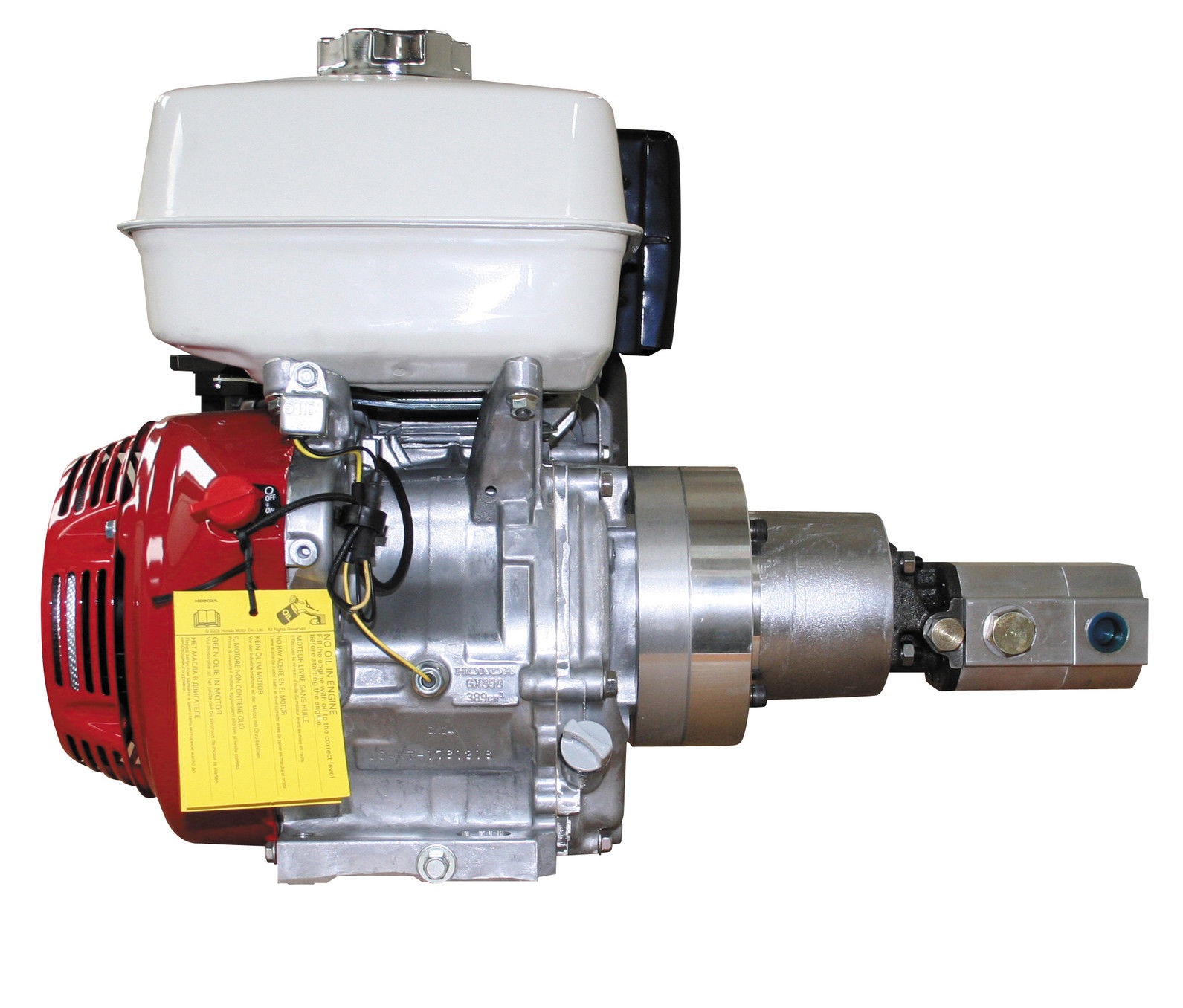
Gas-powered hydraulic pump:Gas-powered pumps are portable hydraulic pumps which are easy to use in outdoor and remote environments. However, they are limited by fuel supply, have higher emissions compared to other hydraulic pumps, and the fuel systems require regular maintenance.
Manual hydraulic pump:They are easy to transport and do not require a power source. However, they are limited by the operator’s physical ability, have a lower flow rate than other hydraulic pump types, and may require extra time to complete tasks.
Hydraulic hand pump:Hydraulic hand pumps are suitable for small-scale, and low-pressure applications and typically cost less than hydraulic foot pumps.
Hydraulic foot pump:Hydraulic foot pumps are suitable for heavy-duty and high-pressure applications and require less effort than hydraulic hand pumps.
Hydraulic pumps can be single-acting or double-acting. Single-acting pumps have a single port that hydraulic fluid enters to extend the pump’s cylinder. Double-acting pumps have two ports, one for extending the cylinder and one for retracting the cylinder.
Single-acting:With single-acting hydraulic pumps, the cylinder extends when hydraulic fluid enters it. The cylinder will retract with a spring, with gravity, or from the load.
Double-acting:With double-acting hydraulic pumps, the cylinder retracts when hydraulic fluid enters the top port. The cylinder goes back to its starting position.
Single-acting:Single-acting hydraulic pumps are suitable for simple applications that only need linear movement in one direction. For example, such as lifting an object or pressing a load.
Double-acting:Double-acting hydraulic pumps are for applications that need precise linear movement in two directions, such as elevators and forklifts.
Pressure:Hydraulic gear pumps and hydraulic vane pumps are suitable for low-pressure applications, and hydraulic piston pumps are suitable for high-pressure applications.
Cost:Gear pumps are the least expensive to purchase and maintain, whereas piston pumps are the most expensive. Vane pumps land somewhere between the other two in cost.
Efficiency:Gear pumps are the least efficient. They typically have 80% efficiency, meaning 10 mechanical horsepower turns into 8 hydraulic horsepower. Vane pumps are more efficient than gear pumps, and piston pumps are the most efficient with up to 95% efficiency.
Automotive industry:In the automotive industry, hydraulic pumps are combined with jacks and engine hoists for lifting vehicles, platforms, heavy loads, and pulling engines.
Process and manufacturing:Heavy-duty hydraulic pumps are used for driving and tapping applications, turning heavy valves, tightening, and expanding applications.
Despite the different pump mechanism types in hydraulic pumps, they are categorized based on size (pressure output) and driving force (manual, air, electric, and fuel-powered). There are several parameters to consider while selecting the right hydraulic pump for an application. The most important parameters are described below:
Source of driving force: Is it to be manually operated (by hand or foot), air from a compressor, electrical power, or a fuel engine as a prime mover? Other factors that may affect the driving force type are whether it will be remotely operated or not, speed of operation, and load requirement.
Speed of operation: If it is a manual hydraulic pump, should it be a single-speed or double-speed? How much volume of fluid per handle stroke? When using a powered hydraulic pump, how much volume per minute? Air, gas, and electric-powered hydraulic pumps are useful for high-volume flows.
Portability: Manual hand hydraulic pumps are usually portable but with lower output, while fuel power has high-output pressure but stationary for remote operations in places without electricity. Electric hydraulic pumps can be both mobile and stationary, as well as air hydraulic pumps. Air hydraulic pumps require compressed air at the operation site.
Operating temperature: The application operating temperature can affect the size of the oil reservoir needed, the type of fluid, and the materials used for the pump components. The oil is the operating fluid but also serves as a cooling liquid in heavy-duty hydraulic pumps.
Operating noise: Consider if the environment has a noise requirement. A hydraulic pump with a fuel engine will generate a higher noise than an electric hydraulic pump of the same size.
Spark-free: Should the hydraulic pump be spark-free due to a possible explosive environment? Remember, most operating fluids are derivatives of petroleum oil, but there are spark-free options.
A hydraulic pump transforms mechanical energy into fluid energy. A relatively low amount of input power can turn into a large amount of output power for lifting heavy loads.
A hydraulic pump works by using mechanical energy to pressurize fluid in a closed system. This pressurized fluid is then used to drive machinery such as excavators, presses, and lifts.
A hydraulic ram pump leverages the energy of falling water to move water to a higher height without the usage of external power. It is made up of a valve, a pressure chamber, and inlet and exit pipes.
A water pump moves water from one area to another, whereas a hydraulic pump"s purpose is to overcome a pressure that is dependent on a load, like a heavy car.

The present invention relates to combustion engines. Specifically, the present invention relates to non-fixed compression ratio, compression ignition, two-stroke, rotating/reciprocating, internal combustion engines that convert combustion energy into direct hydraulic work.
Conventional internal combustion engines use two different processes, constant volume and constant pressure. The constant volume process is characteristic of spark-ignition engines or the Otto cycle. A spark ignition engine uses volatile liquid fuels such as gasoline, compression ratios from 6:1 to 12:1, and compression pressures from 1034 to 2068 kPa. Engine load and speed are controlled by throttling the fuel charge. The constant pressure process is typified by diesel engines or compression ignition engines. A compression ignition engine uses low volatility liquid fuels from fuel oil to crude oil, compression ratios from 11.5:1 to 22:1, and compression pressures from 2768 to 4830 kPa. Engine load and speed are controlled by varying the fuel quantity injected.
Three general types of arrangements of engines are used, four stroke, two stroke, and rotary or Wankel engines. These engines are typically fixed piston engines. That is, the pistons have a predetermined and constant or fixed stroke. This stroke is set up for the particular type of fuel to be used in the engine. Moreover, the pistons are connected through a connecting rod to a crankshaft in order to convert the combustion energy into mechanical work. The crankshaft in turn is used to drive all of the other systems of the automobile or machine. So, the nature of these engines is to produce net mechanical shaft work.
Numerous innovations for combustion engines have been attempted to improve the efficiency, and hence output or work, of an engine without adding undue cost or size. Engines exist that combine the rotation of a rotary engine with the reciprocation of pistons. For example, U.S. Pat. No. 3,990,406 discloses a roto-reciprocating engine arranged to provide an engine that has a large cubic inch displacement per pound of unit weight and therefore a good horsepower to weight ratio. The engine includes a chamber, a piston in the chamber mounted on a crankshaft, and an orientation member arranged to make it possible for the piston to orbit around the crankshaft center while remaining in a substantially oriented position.
U.S. Pat. No. 5,433,176 discloses a rotary-reciprocal combustion engine. The engine includes a rotor which has circular pistons on the lateral peripheral area of the rotor and which is reciprocatively mounted on a rotor with a shaft centrally located in a fixed housing having a cavity formed by a circular peripheral wall and two sidewalls. The circular pistons or sealing mechanisms or apparatus reciprocate on the peripheral area of the rotor while rotating with the rotor and shaft. U.S. Pat. No. 5,070,825 discloses a rotary engine with a wobble plate and a plurality of pistons reciprocating within cylinders.
U.S. Pat. No. 4,166,438 is directed to a machine with reciprocating pistons and a rotating piston carrier. The engine overcomes sealing deficiencies of rotary engines by using conventional pistons. The engine includes a housing surrounding a workshaft, a carrier in the housing about the shaft and rotatable about the shaft axis, a plurality of continuous walls within the carrier each defining a chamber, and a piston in each chamber connected to a crankshaft where each crankshaft is linked to the housing to induce relative movement between the housing and the carrier. Induced motion of the pistons results in a revolution of throw arms of the cranks, causing motion of the gears with respect to the timing gear, thus imposing rotational motion on the carrier and shaft.
Other engines use a free piston arrangement, wherein the stroke of the piston is not set by attachment to a shaft of predetermined length. U.S. Pat. Nos. 4,399,654, 4,561,252, and 4,702,205 disclose such engines. Further, in these engines, the combusted gas exhaust is used to turn vanes in a motor to produce shaft power. U.S. Pat. No. 3,989,011 discloses a constant pressure heating vane engine. This engine uses a system similar to a gas turbine to generate shaft work.
U.S. Pat. No. 5,327,857 discloses a vehicle using a crankless, unthrottled internal combustion engine directly powering its wheels hydrostatically. The vehicle uses a spark or compression ignited two-cycle type engine, an optional recovery and reuse of a portion of its braking energy, and hydraulic pressure for compression of the air and fuel mixture. U.S. Pat. No. 4,382,748 discloses an opposed piston type free piston engine pump for converting combustion energy into hydraulic power. The motion of the engine is at least substantially directly delivered to hydraulic pumping elements, usually, without crankshaft and connecting rod arrangements of conventional rotary engines. The engine includes a pump piston and engine pistons arranged for linear in-line reciprocation wherein the hydraulic pump portion supplies energy for effecting a compression stroke to bring the engine pistons toward one another thereby to effect compression.
In accordance with the present invention a reciprocating rotating internal combustion engine is provided having a more direct conversion of combustible gases into hydraulic pressure. The reciprocating rotating engine utilizes a non-fixed compression ratio free piston having a compression ignited two-stroke reciprocating and rotating cycle. This arrangement permits multi-fuel use.
The reciprocating rotating internal combustion engine for producing direct hydraulic work includes a combustion assembly housing, a combustion chamber disposed within the combustion housing, at least one free piston disposed within the combustion chamber and dividing the combustion chamber into at least a first combustion chamber portion and a second combustion chamber portion, the free piston moveable between a first piston position and a second piston position, a pumping assembly housing, a pumping chamber disposed within the pumping housing, and at least one pump vane disposed within the pumping chamber and dividing the pumping chamber into at least a first pumping chamber and a second pumping chamber, the pump vane coupled to the free piston so as to be moveable therewith between a first pump position and a second pump position corresponding to the first and second piston positions respectively.


 8613371530291