
place diverter hydraulic pump free sample

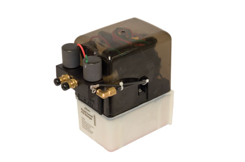
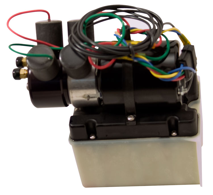
Bennet Marine duel action hydraulic pump designed for Place Diverter. Fits any year Place Diverter. Comes with a 5 year limited warranty (DO NOT get this confused with the Two Solenoid Pump designed for trim tabs)

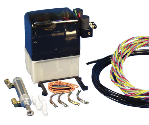
#AT R8607 Manufactured by American Turbine. This unit will bolt up to Berkeley JB/JG, Dominator, American Turbine, & New style Legend jet pumps. Complete Kit witch includes New Nozzle housing **Specify Long snoot or standard nozzle housing.** American turbine diverter,Hyd pump, Hyd cylinder,Rudder, & wiring harness. This is a Complete Bolt on system , giving bow attitude adjustment for faster Holeshot"s and on plain speeds, Or if you"re just looking for that HUGE ROOSTER TAIL!!
The kit is designed to convert your old style Jacuzzi pump to a much more efficient American Turbine style pump. On the average there is a 20% increase in Performance over the original Jacuzzi 12YJ & Golden Eagle Pump. And a 10% increase in Performance over the 12WJ Pump.
ok, im not talkin trash. my buddy was gonna buy a place diverter for his berkeley. so he called a shop (i dont know where) and the guy says why dont you get an aggressor instead, i can get you a killer deal. he tells my buddy that he can get a complete hydraulic control setup for $596. my buddy asked if that was "complete" as in i dont even need to buy a switch or hydraulic lines, or a motor, and the guy says COMPLETE. you dont need anything else. he says the aggressor is the same exact thing.
i guess my question is that how can this be so cheap, i just looked at prices from place, and the whole setup is $876 if there is that much of a price spread for the same thing just different maker than something seems fishy. somebody help me out
That sounds cheap buy it.Chet how do they compare to a place diverter?I boughta place diverter recently and paid 450 diverter and cable but i had a control handle(manual type)
For what ever it is worth. I spent the last four weeks, looking for options for my boat. After several dialogs, and emails - everyone recommended a place diverter over anything else. I installed one last week and it is a dream. My two cents worth!!
That sounds cheap buy it.Chet how do they compare to a place diverter?I boughta place diverter recently and paid 450 diverter and cable but i had a control handle(manual type)
chet, was $690 the hydraulic complete setup, inculding lines, motor, and switch. if so from where. and how come the aggressor is 200 bucks cheaper than place for the same exact thing.
I have a Plave Diverter, and I love it. Manual. I don"t know anything about the Aggressor diverter so I can"t comment on it. I would be curious to know how many people went from a Place to an Aggressor, and vice versa. I would stick with the original developer, Place......but when it comes down to spending less money, Aggressor is the choice.
also that price i got on the place setup is directly from place. these aggressor prices are coming from dealers arent they. which would make what you said the complete opposite. is aggressor know for being inexpensive in all their products?
p.s. one idea i just had was maybe the aggressor diverter is the place. aggressor buys them from place at dealer cost, and puts an aggressor sticker on them. kinda like the ford ranger,and mazda pickup, i dunno.
i was told by cp performance that the diverter that comes standard with the brand new berkeley 12ji pump is a place diverter. thats where i got this idea
If your soul purpose is to throw up a rooster tail, they should both do that for you. Again, I don"t know anyone that uses the Aggressor diverter, so I really don"t know how they perform. I do know how the Place diverter performs, and most boaters use them. If I had to make a purchase, I would like to see if there was any difference between the two. I would talk to other boater here (as your doing) Boaters on the water, maybe someone would have one and could take me for a ride to show me how is works. And I would talk to both mfg"s and also the pump shop I get my work done through. If you do your own pump work, I"d call 3 or 5 pump shops, and see what they say, and take the most recommended option.
From what I understand, Hi Tech does quite a bit of Aggressor sales. If they recommend it, then go for it. Personally, I would get a few other shops opinions since HI TECH pushes Aggressor over other mfg"s. Try Don"s Pump Service, there is a 800 number in the back of Hot Boat.
In that picture of the aggressor diverter it shows the reverse cable and the diverter controls on the opposite side of the nozzle. my question is are they all that way? I dont think I have ever seen one set up like that.
I got emailed about this by someone on this forum, and I must say, it"s very tempting. My only issue with them is this: I"ve had boats that have had Dominator or Berkley pumps for years. Parts are readily available. Remember Drake and Bay Jet. Back in the late 70"s everyone was talking about how cool those might be. Now go find some parts for one of those. I"m not saying Aggresor is a bad pump, I don"t know much about them, but are they going to be around for a while? If I screw the divertor,control box,etc. up 5 years from now, am I going to be able to get parts? I"m with Randy on this. Berk and Dominator are just easier to get parts for!
$596 sounds like a great deal for a full hydraulic set-up. Does anyone have the phone number for Hi-tech that has the special deal? Sounds too good to pass up.
you should look at it this way, is berk going to be around 5 years down the road with all the R&D aggressor does and is doing? You already have the know it all calling berkeley stuff JUNK and they supposedly agree with him so what do you make of it???. Anyways, You mention drake and bayjet, now do those interchange with berkeley? Last i knew they didnt. Well aggressor bolts up to EVERYTHING berkeley so you know and that diverter they make is just as nice as a place anyday and all the "extras" you get charged for on a PD are "standard" on an aggressor. To bad it"s not a better picture up there becuause you"ll notice that fin they have is like the berk race fin on a berk race nozzle. It"s short and swept back like the top fin on a shark. Pretty trick if you ask me and above all it"s CHEAPER. I just checked the hitech website and that price is $696 so i dunno where that 596 came from. If it is that price i"ll say it again...BUY IT! BUY IT! BUY IT! I paid $690 and was smiling ear to ear at the time because CP perf had the same thing in place diverter for close to $800(cheapest i found then) if i remember correctly.
$596 sounds like a great deal for a full hydraulic set-up. Does anyone have the phone number for Hi-tech that has the special deal? Sounds too good to pass up.
1) The price you got directly from Place Diverters is the list price. They sell direct at list price to protect their dealers. If you get a price from cp performance or a similar place diverter dealer the price will be quite a bit less. Also make sure you are not pricing the FTN unit unless you really want it.
2) One thing I would check on the Aggressor unit is the hydraulic pump. Make sure the price you have is with a "Bennet Marine" hydraulic pump. There are some cheaper hydraulic pumps out there but they are just that, cheaper.
Chet, I see that you feel passionately about this. That"s cool. However, I also see this as a comfort factor. You need to trust the stuff that you bolt on your ride. I happen to be a Chevy guy. Do I think that a Ford can"t make horsepower too, no. However, a few old timers that raised me brought me up with Chevy"s, and that"s what I run. As for the Berk/Dom/Agressor decision, I never said that the agressor is bad. It"s new. I don"t know about it. Berk has made some crap (C pump). Time shook out the good and the bad in the berk line. Dominator is just a copy of the good berk. It"s nice to know that the Agressor stuff bolts up. I still think that I personally am comfy with my Dominator. PD has been around the block a few times. It may be more exopensive, but I know that the hydraulic pump works and that most marine shops have replacement parts. Not too many Agressor parts around here. If the hydraulic unit gives up, or the switches die, while I"m at the river, I might have to park it if I can"t get parts. No offense. I am seriously thinking about the Agressor as all I have on my pump is a Berkley droop with the race fin, and it makes skiing and wake boarding a bitch. 100 foot ropes suck. I just need to be comfy, but I haven"t heard or seen enough. Opinions are like a$$holes, everyones got one.
Just a footnote from this penut gallery.The Place unit using the Bennett trim pump exclusively ,which is basically bullettproof.You could use a sterndrive trim pump [fraction of the cost of a bennett unit]for your diverter if you wanted to.What pump does Aggressor using? Just a question ,no flame intended! BTW both units look great in my book !
Folks, there is a substantial difference between the two. First, the Agressor comes with a changable nozzle at no extra cost (if my memory serves correctly). Second, if you have ever had the nozzle out of your Place, you will see a pretty substantial "ledge" that your jet-stream must pass before exit. agressor took just the opposite approach, like putting a glass on top of a bottle. (a smooth unrestricted transition from divirter to nozzle.) I"ve looked at both very closly, and would have to say that the Agressor is superior in casting quality, and overall finish.
it"s not really passionate, it"s just knowing a good deal when you see it. I too am a chevy guy(all 522cu) and i would never own a ford although there was an article in a very old hotrod mag i believe showing that there is more power to be had out of a 460 at less money than the 454 at the same power/money invested. I didnt believe it till i read it with my own eyes. Anyways, what"s with the "trust" issue??? Nothing has happened to me yet, is there something i should know about? I havent run my boat with the diverter yet but everything else has been great without any problems. I looked at them both too and was hard pressed to find ANY differnce aside from the price and the name of course. I think your just buying the name for the extra money, it"s pretty much the same ( mine even has the bennett trim pump)but it"s cheaper (and nicer actually like KenF said) so.....i bought the aggressor. FYI, i notice they make them now with an oildyne pump which doesn"t have the solinoids and has more pressure which makes it faster up and down from what i gather. As you said opinions are like assholes though and i have will have a big one when i run 90+. http://free.***boat.net/ubb/smile.gif
See now Chet, just like I said, I hadn"t heard much about the Agressor. Now you"re telling me things that can help me make a more informed decision. Interesting stuff. I was comfortable with place because I see them run and hear unsolicited testimonials. All I"ve gotten about Agressor was that it"s cheap, and that the guy at Commander wanted to make sure I knew that it was better (though he couldn"t tell me why.) I like the fact that the parts that are attatched to the fabricated parts are reputable. I certainly wasn"t saying this to bust your balls, just telling why some of us are wary. If you"re going 90, wave when you pass me! http://free.***boat.net/ubb/biggrin.gif
Duane from HI-Tech has a passion for jet boats just like all of us do (if not more), I have spent a lot of money with him ( 2 Boats) never to be let down. Every thing is what he`s said it was. Dave from Aggressor has the same passion, He`s taken a market that was falling on it`s nose and put "hope back in to it". Duane is the inventor of a lot of jet pump parts, Jet-A-way, Prim-A-Jet and Ultimate Wear Ring are just a few of the things he`s done. These products are light years a head of copies on the market. Dave has put life back in to the pumps with his new designs and giving us more of a choice on bowl and other parts.Aggressor parts are far from cheap, Dave has found ways to cut cost "not to produce cheap parts" His parts are just like Duane`s "light years a head of others"
Duane has been involved in jet pump parts and repair for over 30+ years and he`s had his hands in a lot of things we all run now! He`s like a BIG BOOK OF KNOWLEDGE as I have found out "that man knows his shit".
As far as parts being "Light Years" ahead of there time, give me a break. Just like the Jet Hydro will soon be the fastest drag jet boat ever. Like I said before, this isn"t rocket science. Given the time, money and resources, anything is possible, and anyone can make pump parts when they have the above three elements. If the Aggressor (or any mfg) parts were far more superior, and advanced for our time, do you think guys like Duane would have a job? If impellers and bowls were made without any imperfections from ski to race boats, would these pump builders like Duane, Jack, Tom Papp, GS have business in the pump industry? I think not!
I didn"t take the photo I posted and haven"t seen enough Aggressor diverters to remember if the cables are on the correct side. It is possible it is a reverse negative. In other words the negative was printed on paper upside down. I saw a picture of Cindy Crawford once where her mole was on the wrong side....oooops. I"ve also seen one of her without the mole. She didn"t like that much since it is a psuedo trademark.
MBF, Inc. has over 42 years experience in research, design and manufacturing of custom alloyed pumps and impellers. They pour over 2,000,000 pounds annually in pumps, impeller parts and complete pump systems. The foundry produces impellers and systems from 3 to 44 in diameter. Additionally, they are the only jet drive manufacture that continues to improve and develope it"s out of the box jet drives. A good example is the two types of dual jet drives soon to be available.
Folks, there is a substantial difference between the two. First, the Agressor comes with a changable nozzle at no extra cost (if my memory serves correctly). Second, if you have ever had the nozzle out of your Place, you will see a pretty substantial "ledge" that your jet-stream must pass before exit. agressor took just the opposite approach, like putting a glass on top of a bottle. (a smooth unrestricted transition from divirter to nozzle.) I"ve looked at both very closly, and would have to say that the Agressor is superior in casting quality, and overall finish.
I don"t understand why this post has turned into a "bashing" issue. Some of us just don"t have as much experience with Aggressor as we do with Berk/Dominator. As for the eight years of experience and R&D, that"s impressive. But, as they say, the proof is in the pudding. Also, as I read in another post, we all run the stuff we can afford. Most of us that own 15 to 20 year old boats are going to be running a berk, Dominator, or God forbid a Jacuzzi. This is what I can afford these days, so this is what my exposure is limited to. I"d love to try out an Aggresor, or American Turbine and have a pump guy really trick it up. I just haven"t got that kind of money to spend, so I"m back to being very framilar with Berk and Dominator...
That boat belongs to RR1/001. It is a Jet Hydro that he races in the RiverRacer class. Right now, I think it runs 12"s. The pump is an Aggressor pump, and the ride plate is some new technology RR1/001 won"t discuss with us yet. http://free.***boat.net/ubb/frown.gif RR1/001 could better inform you on the details.
Back to the original topic, I called and ordered the whole setup complete with the "Bennet Marine" pump shipped to my door for about $625.00 After I get some time with it I post my thoughts of the product for anyone out there who cares.
Chet, it`s kinda funny in a screwed up way...lol... HBjet says he doesn"t bash mfg`s or shops but every time there is an Aggressor topic he`s in there "like fly`s on shit" running these people down like he`s some kind of "jet pump god."
I`v made him some offers that wouldn"t cost him a dime and he has chose to decline on the offers! If he was the big jet pump research person he lets on to be he would have jumped on the chance to prove his claims to the world.
When I joined this web site they took me in with open arms, some of them even put links to my web site on their`s, Told me I had a cool looking jet boat. As time went on I played their game until "The Big Bowl Shot Out" Then I was a dick, I had jumped sides and joined up with Chet http://free.***boat.net/ubb/smile.gif The next step was when I got the Aggressor deal for the new pump, I now had a shit box for a boat and my web site links were taken off of their web sites.
HBjet just give up! You fighting a fight your NOT going to win! Think about it "if you were so Dam Smart about jet pumps why don"t you start up HBjet pump mfg." http://www.plauder-smilies.de/sad/nixweiss.gif
BTW, I read your offer. But like I mentiond before. My pump isn"t set back, so changing bowls isn"t as easy as a set back. In case you haven"t been following the leader, you would see where I"ve asked Dave from Aggressor 3 times that if I pay upfront for an out of the box bowl and impeller, would I get a money back quarantee if I don"t see a minimum of 5 mph increase (that is what he said the two parts would do on stock power) I have yet to get any type of response.....So why don"t you ask your sponser to back up there claim. I am and I"m getting nothing.
I know I have picked on RR1/001 because of the boat he choose to race. Should have never done that, Sorry. It is no secret who I choose for my pump and motor work MPD and DNE. Jack and Dave are two of the most helpful and knowledgeable people I know. And For Dave that is a huge compliment. I have an extensive automotive back ground. I was and Instructor Melior institute contracted to General motors and now work for Robert Bosch inc. also as an Instructor. If some one asked me I will recommend MPD and DNE. But have been known to also offer up Teddy (CBMjet) as a good resource also. So if you want to make an intelligent argument to my test I will love to have a respectful debate with you if not go away..... My .02
Chet, it`s kinda funny in a screwed up way...lol... HBjet says he doesn"t bash mfg`s or shops but every time there is an Aggressor topic he`s in there "like fly`s on shit" running these people down like he`s some kind of "jet pump god."
I`v made him some offers that wouldn"t cost him a dime and he has chose to decline on the offers! If he was the big jet pump research person he lets on to be he would have jumped on the chance to prove his claims to the world.
When I joined this web site they took me in with open arms, some of them even put links to my web site on their`s, Told me I had a cool looking jet boat. As time went on I played their game until "The Big Bowl Shot Out" Then I was a dick, I had jumped sides and joined up with Chet http://free.***boat.net/ubb/smile.gif The next step was when I got the Aggressor deal for the new pump, I now had a shit box for a boat and my web site links were taken off of their web sites.
HBjet just give up! You fighting a fight your NOT going to win! Think about it "if you were so Dam Smart about jet pumps why don"t you start up HBjet pump mfg." http://www.plauder-smilies.de/sad/nixweiss.gif
I must tell Chet Thanks for starting so much shit because Now I have a pump that I can put as much HP to as I want and never look back http://free.***boat.net/ubb/smile.gif
stay on the topic and then move on. Just wondering, how old are some of you babys? I"m 44 and I swear I think some of you ****s are still shiting in your pants! Damm shame, this could be a much better place.
HammerDown has a good point. I`m done with this topic. jester said he wanted the phone number to HI-Tech, I gave it to him and he said his new Aggressor diverter was on it`s way.
HammerDown, I think you bring up a very valid point as well that this aggressor thing has gotten WAY OUTTA HAND.. I don"t pretend to know anything about pump boats, but I do know investment casting, and I know it well since I"m in the industry of making patterns for it and managing jobs as they go through the foundry.
stay on the topic and then move on. Just wondering, how old are some of you babys? I"m 44 and I swear I think some of you ****s are still shiting in your pants! Damm shame, this could be a much better place.
This electric solenoid operated diverter valve allows you to easily add another hydraulic function such as a grapple to your John Deere subcompact tractor. Our kit is designed to be plumbed in line with your loaders tilt function. Fluid passes through Ports P1/P2 to C/D when the trigger is pulled on the included joystick handle. Then, the flow of fluid will switch from the tilt cylinder to the new auxiliary circuit (A/B). To open and close the auxiliary circuit, press and hold the trigger and move the joystick side to side to open and close the auxiliary cylinder. As soon as the trigger is released, flow will automatically switch back to allow use of the tilt function.
ALL PRODUCT AND COMPANY NAMES ARE TRADEMARKS™ OR REGISTERED® TRADEMARKS OF THEIR RESPECTIVE HOLDERS. USE OF THEM DOES NOT IMPLY ANY AFFILIATION WITH OR ENDORSEMENT BY THEM. ANY PRODUCT NAMES, LOGOS, BRANDS, AND OTHER TRADEMARKS OR IMAGES FEATURED OR REFERRED TO WITHIN THE SUMMIT-HYDRAULICS.COM WEBSITE ARE THE PROPERTY OF THEIR RESPECTIVE TRADEMARK HOLDERS. THESE TRADEMARK HOLDERS ARE NOT AFFILIATED WITH SUMMIT HYDRAULICS, OUR PRODUCTS, OR OUR WEBSITES. THEY DO NOT SPONSOR OR ENDORSE SUMMIT HYDRAULICS OR ANY OF OUR PRODUCTS. BOBCAT®, CAT®, JOHN DEERE®, KUBOTA®, KIOTI®, LS®, NEW HOLLAND® ARE TRADEMARKS OF THEIR RESPECTIVE OWNERS AND ARE NOT AFFILIATED, ENDORSED, CONNECTED, OR SPONSORED IN ANY WAY TO THIS WEBSITE OR ANY OF OUR AFFILIATE SITES.
Conventional passive, semi-active, and active hydraulic dampers and shock absorbers typically include a piston and an attached piston rod that move through a cylindrical housing in response to forces applied by the vehicle body, the road surface, and/or a source of hydraulic pressure. Occasionally, operating conditions are such that the piston travel relative to the housing may be excessive, i.e. beyond its normal stroke. Under such circumstances, the piston, or other elements that move relative to the housing, may collide with objects located at either end of the housing that remain stationary relative to the housing. Bump stops, typically fabricated from relatively soft materials, such as for example, rubber or plastic, may be used at one or both ends to diminish the damage that may result from such collisions. However, bump stops made of rubber and other similar materials do not always offer sufficient protection, can be noisy, and can be easily damaged so that they no longer function properly. High forces and temperatures may also cause such bump stops to be extruded and/or migrate from their original configurations, or otherwise interfere with the operation or performance of other components in the housing, such as for example, diverter valves. Repeated impact may also cause pieces of the bump stop to break off and be carried to other parts of the system, for example, in a hydraulic active suspension fluid circuit, which may result in a partial or complete system failure.
When a piston moves through a shock absorber or actuator housing, it typically displaces a quantity of fluid at a rate that is proportional to the speed of the piston. In vehicle active suspension systems, at least one diverter valve may be used to at least partially divert hydraulic fluid displaced by the movement of the piston away from a hydraulic pump that normally would receive this fluid. Such a diverter valve is typically a passive valve that is activated in response to the hydraulic fluid flowing at a rate that exceeds a fluid diversion threshold.
In some embodiments, a bi-directional hydraulic diverter valve that includes a diverter valve housing, and at least one diverter valve spool that is located at least partially in the diverter valve housing. The spool may be biased towards a closed position, by for example a coil spring. The diverter valve may establish a first fluid flow path that directs fluid flow in at least a first direction and a second direction through the diverter valve housing. In addition, a bypass fluid flow path for fluid flow may be established that redirects at least a portion of the fluid flow that passes through the first fluid flow path. The bypass fluid flow path may be open when the at least one diverter valve spool is in the open or partial open position and the bypass fluid flow path is closed when the at least one diverter valve spool is in a closed position. At a first operating point hydraulic fluid may flow through the first fluid flow path in the first direction when the diverter valve spool and associated bypass flow path are closed. At a second operating point, hydraulic fluid flows through the first fluid flow path in the second direction and the diverter valve spool and associated bypass flow path may be closed. At a third operating point hydraulic fluid flows through the first fluid flow path in at least one of the first direction and the second direction and the diverter valve spool and associated bypass flow path are open. A bi-directional hydraulic diverter valve may have one or more spools.
In some embodiments, a hydraulic actuator includes a housing with an internal volume with a compression volume and an extension volume. These volumes are at least partially filled with hydraulic fluid. A piston is disposed in the housing, where at least a portion of the hydraulic fluid contained in the compression volume is displaced from the compression volume when the piston moves at least partially through a compression stroke, and/or at least a portion of the hydraulic fluid contained in the extension volume is displaced from the extension volume when the piston moves at least partially through an extension stroke. A hydraulic bump stop that at least temporarily traps a quantity of fluid on a side of the piston that is in the direction of motion. The bump stop may include a valve that allows the quantity of fluid to escape when the pressure reaches a predetermine threshold pressure. In some embodiments, a hydraulic bump stop may include a sealing device, such as for example a disk or a plug, that acts on a surface or device in the actuator to temporarily trap a quantity of fluid adjacent to a piston face that is in the direction of motion of the piston. Once the fluid is trapped, further motion of the piston in the same direction increases the pressure of the trapped quantity of fluid and resists the motion of the piston. The pressure of the trapped quantity of fluid may be regulated or relieved by allowing at least some of the trapped fluid to escape through a valve such as a blow-off valve.
U.S. patent application Ser. No. 14/602,463, entitled “ACTIVE VEHICLE SUSPENSION SYSTEM,” which describes the operation of a diverter valve that is included in the housing of an actuator, is incorporated herein by reference in its entirety. U.S. Pat. No. 8,839,920, entitled “HYDRAULIC ENERGY TRANSFER,” which describes a shock absorber that may be used to apply active or resistive force, is incorporated herein by reference in its entirety. U.S. Pat. Nos. 8,376,100; 8,392,030; and 8,841,786; each of which is hereby incorporated by reference herein in its entirety, disclose various other aspects of active suspension systems.
Paragraphs [1637]-[1824] of U.S. patent application Ser. No. 14/602,463, entitled “ACTIVE VEHICLE SUSPENSION SYSTEM,” describe the operation of an embodiment of a diverter valve and how the pressure forces are balanced so that the movement of the spool is primarily in response to the velocity or volume flow rate of the fluid passing through the valve. Diverter valves are typically activated by flow in a single direction.
FIG. 1 illustrates an aspect of an embodiment comprising a triple tube damper housing with a piston, piston rod, and a hydraulic bump stop, comprising a slotted sealing disk where the piston is in a normal operating position.
FIG. 8 depicts the relationship between pressure, in the pressure tube of an exemplary damper configured with a hydraulic bump stop, and the displacement of the piston.
FIG. 9 illustrates another aspect of an embodiment of a damper comprising a piston, a piston rod, and a hydraulic bump stop with an increased leakage path around a seated slotted sealing disk.
FIG. 10 illustrates another aspect of an embodiment of a damper comprising a piston, a piston rod, and a hydraulic bump stop with orifices in the slotted sealing disk that allow controlled flow past the ring when it is seated.
FIG. 11 illustrates another aspect of an embodiment of a damper comprising a piston, a piston rod, and a hydraulic bump stop with a slotted sealing disk that is configured with a variable orifice mechanism in the open position.
FIG. 13 illustrates another aspect of an embodiment of a damper comprising a piston, a piston rod, a progressive hydraulic bump stop, and a mechanical bump stop with a sloping radial surface for engaging the slotted sealing disk.
FIG. 15 illustrates another aspect of an embodiment of a damper comprising a piston, a piston rod, and a hydraulic bump stop with a tandem slotted sealing disk.
FIG. 17 depicts the relationship between pressure, in the pressure tube of an exemplary damper configured with a hydraulic bump stop, and the displacement of the piston with a gradual pressure transition.
FIG. 18 illustrates another aspect of an embodiment of a damper comprising a piston, a piston rod, and a hydraulic bump stop with a closure plug that is configured to mate with the diverter valve assembly.
FIG. 24 illustrates a cross section of the embodiment of the dual-spool diverter valve of FIG. 21 in a normal operating mode, where neither the inner nor the outer spool is activated.
FIG. 26 illustrates an isometric view of a partial cross section of the embodiment of the dual-spool diverter valve of FIG. 21, where the inner spool is activated.
FIG. 34 depicts a schematic of an aspect of the fluid flow paths of an active hydraulic system actuator and the single-spool bi-directional diverter valve of FIG. 32.
According to one aspect, a suspension system shock absorber, damper, or actuator includes a housing which is separated into a compression volume and an extension volume by a piston. In a first mode, the piston moves through at least a portion of a compression stroke, while in a second mode, the piston moves at least partially through an extension stroke. One or more hydraulic bump stops may be used to apply a resistive force on the piston, at one or both extremes of the piston stroke, to rapidly slow the motion of the piston after a certain point in its stroke. Hydraulic bump stops may be engaged as an alternative to or in addition to conventional bump stops.
As used herein, the term “extension volume” refers to the volume available for hydraulic fluid in the housing of a damper or actuator, on the same side of the piston as the piston rod. As used herein, the term “compression volume” refers to the volume available for hydraulic fluid in the housing of a damper or actuator, on the opposite side of the piston from the piston rod.
Hydraulic bump stops are established by causing the motion of the piston to trap a quantity of fluid in a manner that resists the further motion of the piston in a given direction. The trapped fluid is allowed to escape through one or more restrictions, such that the pressure of the trapped fluid increases sufficiently to resist the motion of the piston.
Aspects of some embodiments relate to a diverter valve which is a device that may be used to prevent overspinning of a hydraulic motor/pump in a hydraulic circuit, such as for example, the hydraulic circuit of an active suspension actuator. A diverter valve is a multi-path fluid flow control valve for a shock absorber or other hydraulic circuit that restricts fluid flow to a first path while directing fluid flow to a second path when a preset fluid flow velocity is reached in the first path.
Diverter valves in a hydraulic system typically include at least one fluid flow path through which fluid flows during operation. Embodiments of a spool type diverter valves include at least one spool that is biased in a closed position by a spring or other similar device that applies a bias force. When the flow rate of fluid through the diverter valve increases during operation of the hydraulic system at least one spool converts at least a portion of the kinetic energy of the fluid, impinging on at least one surface of the spool, into static pressure. The balance of the fluid pressure that acts on all the surfaces of the spool is altered in a manner that produces a net force on the spool that opposes the spring that holds the spool in a closed position. When the flow rate surpasses an opening threshold flow rate the net force due to the increased static pressure over comes the bias force and fully or partially activates the spool. The fully or partially activated spool moves in a manner that at least partially opens at least one other flow path for fluid flow through the diverter valve. When the fluid flow rate drops below a closing threshold value, the total static pressure applied to the spool drops and the bias force causes the diverter valve to move towards a more closed or to fully closed position. The opening threshold flow rate may be equal to or different from the closing threshold flow rate.
Applications include active suspension dampers, where diverter valves are used to limit the maximum RPM of a hydraulic motor/pump in the circuit. For such a system, in one mode the diverter valve may allow the entirety of the fluid flow from the first path to move into the hydraulic motor. When the velocity of the fluid flow reaches a tunable set point in a second mode, the diverter valve restricts flow to the hydraulic motor and allows a portion of the flow to bypass the hydraulic motor. In some cases, one or more progressive damping valves are utilized in series or in parallel to smooth damping characteristics during, before, and after transitions.
In one embodiment, a single diverter valve is activated by flow in at least two directions. An embodiment of such a diverter valve is a dual-spool bi-directional diverter valve (DSDV), which is an integrated, dual action (bi-directional) diverter valve comprising a dual-spool design that can function as a bypass in both compression and extension strokes where overspinning of the hydraulic motor/pump would otherwise occur. Typically, two separate diverter valves would be used to prevent overspinning of the hydraulic motor/pump in each stroke direction, i.e. compression and extension. This single dual-spool diverter occupies less space and for example allows for less dead-length in the damper because it combines the functionality of both a compression diverter valve and an extension diverter valve into a single unit. Reducing dead-length in the damper increases the axial range of motion of the shock absorber system, allowing for higher system effectiveness and durability in encountering deep depressions, such as for example, a deep pothole, or high elevations, such as for example, a large speed bump or curb.
Another embodiment of a bi-directional diverter valve that may be activated by flow in at least two directions is a single-spool bi-directional diverter valve (SSDV). The single-spool diverter valve is an integrated, bi-directional diverter valve that includes a single moveable sealing element that may be activated by flow during compression and/or extension strokes where overspinning of the hydraulic motor/pump would otherwise occur. This design includes a single moveable sealing spool that can be induced to move by flow in either of two directions.
The DSDV and SSDV embodiments reduce the mechanical complexity and size of the shock absorber by combining the functionality of two single directional diverter assemblies, where one functions only in compression and a second functions only in extension, into one hydro-mechanical device. Using one device for both compression and extension also reduces material, manufacturing and assembly costs. Typically an SSDV would have an even lower parts count and would be easier to assemble and be more durable than a DSDV.
FIG. 1 illustrates an aspect of an embodiment of a triple tube damper housing 1 with a piston 2, piston rod 3, and a hydraulic bump stop with a slotted sealing disk 4. A hydraulic bump stop is an arrangement components that act in concert to increase hydraulic pressure applied to the piston that resists its motion when it has reached a predetermined point in its stroke. In FIG. 1, the piston is shown in a mid-stroke operating position in the pressure tube 5. The piston 2 is attached to the neck 3 aof rod 3 and divides the volume within pressure tube 5 into a compression volume 6 and an extension volume 7. Slotted sealing disk 4 is attached to piston 2 by an intervening compressible member 8. The slotted sealing disk 4 is biased against annular shoulder 9 formed between rod 3 and neck 3 aby a force exerted by compressible member 8. The outside diameter of the sealing disk 4 has a small diametrical clearance with the bore of the pressure tube 5. The small diametrical clearance permits a significant pressure buildup across the sealing disk when it is seated without the sealing disk coming into contact with the bore of the pressure tube 5. In embodiments, the small diametrical clearance may be in the range of 0.002 inches to 0.02 inches. In the embodiment in FIG. 1, during normal operation when the piston moves at least partially through an extension stroke, fluid may flow out of the extension volume and be directed by diverter valve 10 (shown without detail) to annular channel 11 formed by pressure tube 5 and middle tube 12. Alternatively, fluid may be directed by valve 10 into annular channel 13 formed between the middle tube 12 and outer tube 14. Fluid may also be directed into both channels simultaneously. A compressible member 8 may be, for example, a cylindrical coil spring, a conical coil spring, a wave spring, or an elastomeric spring. In some embodiments, there may be free flow of fluid across the compressible member in the radial and/or axial direction and the fully compressed height of the compressible member may be minimized.
FIG. 3 depicts the embodiment shown in FIG. 1 with the piston at the maximum extension point of its stroke during normal operation. At this maximum normal extension, slotted sealing disk 4 is engaged by a sealing surface 16 which in this case is a radially outwardly extending annular surface of annular stationary mechanical stop 30. Once disk 4 is engaged by surface 16, the surface blocks slots 20 a-20 c. Further, the disk and annular passage 17 are sized such that fluid flow between the intervening volume 31 located between the back face of the piston and disk 4, is substantially trapped, i.e. the fluid is prevented from flowing from the intervening volume to the annular passage and the diverter valve. Cylindrical opening 32 in mechanical stop 30 slideably receives rod 3.
FIG. 4 depicts the embodiment shown in FIG. 1 where the piston has moved beyond the point where the fluid in volume 31 is initially trapped. This continued movement of the piston relative to the now sealed and stationary sealing disk 4 causes the pressure in the intervening claim 31 located between the piston and the sealing disk to increase, thus resisting the motion of the piston. This volume of isolated hydraulic fluid with an increased pressure relative to hydraulic fluid located on the other side of the piston then functions as a hydraulic bump stop that resists further movement of the piston. In some embodiments, once the pressure increases sufficiently, it causes the BOV 15 bto open allowing some of the fluid trapped in volume 31 to escape to the compression volume. In the embodiment shown in FIG. 1-5, at least the piston 2, the compressible member 8, the BOV 15 b, the slotted disk 4, and the annular stationary mechanical stop 30 work in concert to form a hydraulic bump stop.
In some embodiments, it may be desirable to combine a hydraulic bump stop with other mechanisms for limiting movement of a piston. For example, in one embodiment, as depicted in FIG. 5, the motion of a piston is further slowed and/or stopped by using a moving mechanical stop 40 attached to or adjacent to the back face of the piston in conjunction with the pressure applied to the back face of the piston by the hydraulic bump stop.
FIG. 6 illustrates an aspect of an embodiment of a hydraulic circuit of an active suspension system 50 comprising an actuator 51 which includes a piston 52 with a piston rod 53. The piston 52 is slideably received in actuator housing 54 and divides its internal volume into compression volume 55 and extension volume 56. Piston 52 is attached to neck 53 aof rod 53. The compression volume is reduced when the piston rod is moved further into the housing, while the extension volume is reduced when the piston rod is moved out of the housing. In some embodiments, accumulator (reservoir) 57 is incorporated in actuator housing 54 and separated from compression volume 55 by floating piston 58. An additional or alternative accumulator may be incorporated in the upper portion of actuator housing 54 and may be separated from extension volume 56 by an annular floating piston (not shown). An accumulator may also be located external to the actuator housing 54 and configured to be in fluid communication with the compression volume or the extension volume.
The hydraulic circuit of an active suspension system 50 further includes a hydraulic motor/pump (HMP) 59. In some embodiments, the HMP is a positive displacement device so that the piston 52 and the HMP may move substantially in lockstep with each other. Without wishing to be bound by theory, in such an arrangement, the movement of the actuator piston 52 can be controlled more effectively in both absorbing and driving modes. Therefore, while embodiments below are described relative to a HMP, the embodiments may be used with a pump, or hydraulic motor, where appropriate as the disclosure is not so limited.
FIG. 6 illustrates the use of bypass valves to prevent damage to the HMP due to overspeeding. For example, if the actuator 51 is being compressed at an excessive rate, at least a portion of the fluid flowing out of the compression volume 55 may be bypassed so that it flows directly into the extension volume 56 without passing through the HMP. Fluid flowing out of the compression volume may be partially or completely diverted by the bypass valve 60. Fluid flowing out of the extension volume may be partially or completely diverted by bypass valve 61. In some embodiments, bypass valves 60 and 61 are passive diverter valves that are self-actuated when the velocities of fluid leaving the housing 54 exceeds a threshold value. In FIG. 6, the bypass valves are shown to be external to actuator housing 54. In some embodiments, one or both of these valves may be integrated with the actuator housing.
HMP 59 is operatively coupled with an electric motor/generator 63, which is used to both drive the HMP when it needs to be operated as a pump or to absorb power when the HMP is functioning as a motor. Local electronic controller 64 is used to operate the motor/generator in response to various measurements and the output of internal and/or external sensors.
Compressible member 65, slotted sealing disk 66, and stationary mechanical stop 67 work in conjunction with BOV 62 bto trap fluid behind the piston and form a hydraulic bump stop that can be used to slow and/or stop the motion of the piston using hydraulic pressure. A hydraulic bump stop is defined as any mechanism that traps hydraulic fluid in a manner that increases the resistive pressure against a face of the piston of a hydraulic damper, actuator, or shock absorber. In some embodiments, the pressure may be controlled by using at least one BOV in the piston. In some embodiments, the maximum level of pressure may be determined by tuning at least one BOV in the piston. Although, the hydraulic bump stop in FIG. 1 is depicted to be on the extension volume side of the piston, embodiments are not so limited. The moving bump stop elements may be attached to either face of the piston or even be stationary and attached to either end of the pressure tube.
FIG. 7 depicts a perspective view of an embodiment of a hydraulic piston 70 of a hydraulic damper, piston rod 71, wave spring 72, and slotted sealing disk 73, with slots 73 a-73 b.
FIG. 8 depicts a graph 80 of the relationship between pressure in the pressure tube of an exemplary damper configured with a hydraulic bump stop and the displacement of the piston. The data was collected using a damper with a piston diameter of 36 mm and stroke of 120 mm and the bump stop illustrated in FIG. 1. The test was conducted using a dynamometer that was only able to drive the damper through a stroke of approximately 50 mm. When the slotted sealing ring engages the stationary mechanical stop at point 81, the pressure increases sharply in the negative (i.e. expansion) direction. This sharp rise in pressure may result in undesirable noise, vibration and harshness (NVH) in the vehicle. Although it is a requirement of the hydraulic bump stop to rapidly increase the pressure in the damper to arrest damper motion, it may be desirable to smooth (or round) the transition point when the slotted sealing ring engages the stationary mechanical stop.
The embodiments in FIGS. 9-13 illustrate various configurations for inducing a more gradual increase in the rate of pressure rise when a sealing ring engages a stationary mechanical stop in a hydraulic bump stop.
FIG. 9 illustrates an aspect of another embodiment of a triple tube damper 90 with a hydraulic bump stop 91, including piston 2, check valve 15 b, compressible member 8, and slotted sealing disk 92. The clearance between the outer diameter of disk 92 and bore of pressure tube 5 has been increased, relative to disk 4 depicted in FIG. 1, to allow greater leakage past the disk when mechanical stop 30 is engaged by slotted disk 92. This is in order to reduce the initial rate of increase of pressure when the bump-stop is activated. The increased diametrical clearance in some embodiments may be in the range of 0.02 inches to 0.1 inches.
FIG. 10 illustrates an aspect of a further embodiment of a triple tube damper 100 with hydraulic bump stop 101 including piston 2, check valve 15 b, compressible member 8, and slotted sealing disk 102. Flow passages 103 aand 103 bare arranged at a radial location beyond the corresponding sealing surface of the mechanical stop 30 which allows flow through the disk when mechanical stop 30 is engaged by slotted disk 102. The flow passages 103 aand 103 bmay have any appropriate size or shape, and to selected to limit the initial rate of rise of pressure to a desired value when a bump-stop including such a feature is activated.
FIG. 11 illustrates an aspect of a further embodiment of a triple tube damper 110 with hydraulic bump stop 111 including piston 2, check valve 15 b, compressible member 8, and slotted sealing disk 112. Flow passage 113 located outside the sealing surface of mechanical stop 30 allows flow through the disk when mechanical stop 30 is engaged by slotted disk 112. This is in order to reduce the initial rate of increase of pressure when the bump-stop is activated. Spring-loaded check valve mechanism 114 that restricts or totally stops the flow through flow passage 113. Specifically, the spring biases the valve towards the open position, but once the flow through the flow passage exceeds a threshold value, the valve closes. Although a single flow passage 113 is shown in FIG. 11, one or more additional flow passages may be utilized. Spring-loaded check valve mechanisms may be used with these additional flow passages as well. By configuring multiple check valve mechanisms associated with a corresponding plurality of flow passages to activate at different pressures or flow rates, the pressure increase profile behind the bump stop may be finely tuned.
FIG. 13 illustrates an aspect of a further embodiment of a triple tube damper 120 with a hydraulic bump stop 121, including piston 2, BOV 15 b, compressible member 8, and slotted sealing disk 122. The stationary mechanical stop 123 is configured with a radially sloping surface 123 a. When the stationary mechanical stop 123 first engages the slotted disk 122, the one or more slots 123 b(only one slot is shown) are not fully blocked by the sloping surface 123 aand limited flow continues to leak through the slotted disk. This leakage flow limits that rate of pressure rise in the hydraulic bump stop. As illustrated in FIG. 14, as the pressure in the bump stop climbs, the slotted disk 122 is deformed such that surface 122 amore closely conforms to surface 123 a. With increasing deformation, the slot(s) 123 bare increasingly blocked thus more fully sealing the remaining fluid in the hydraulic bump stop.
FIG. 15 illustrates an aspect of still another embodiment of a triple tube damper 130 with a hydraulic bump stop 131 including piston 2, BOV 15 b, compressible member 8, and tandem slotted sealing disk. When the leading disk 132 ais engaged by stationary mechanical stop 30, the slot(s) in disk 132 aare blocked but the increase of pressure in the bump stop is limited by bypass paths 132 cand 132 d. If the motion of the piston continues, the intervening compressible element 133 between tandem disks is compressed. When the compressible element 133 is fully compressed, tandem disks come together and are in full contact as illustrated in FIG. 16. Consequently, the bypass flow paths 132 cand 132 dare blocked by disk 132 b. The disk 132 bmay be constructed as a separate component and with a compressible element as shown, or the disk 132 bmay be a flexible disk attached to disk 132 bthat will deflect under pressure to restrict or totally block flow through passage(s) 132 cand 132 d.
FIG. 17 depicts a graph 140 of the relationship between piston displacement and pressure in the pressure tube of an exemplary damper configured with a hydraulic bump stop with progressive engagement as described above and shown in FIGS. 11-13. At point 141, the rate of pressure increase produced by the hydraulic bump stop is curtailed by using progressive engagement between the slotted disk(s) and the stationary mechanical stop.
FIG. 18 illustrates an aspect of another embodiment of a triple tube damper housing 1 with a piston 2, piston rod 3, and a hydraulic bump stop with a closure plug 150. Closure plug 150 is substantially cylindrical with a central cylindrical axial opening that slideably receives piston rod 3. Closure plug 150 includes a conical frustum section 151 at one end and a cylindrical section 152 at the second end with a radially outwardly extending flange 153 which forms an annular sealing surface 154.
In FIG. 18, the piston is shown in a mid-stroke operating position in the pressure tube 5. The piston 2 is attached to the rod 3 and divides the volume within pressure tube 5 into a compression volume 6 and an extension volume 7. Closure plug 150 is attached to piston 2 by an intervening compressible member 8. In the embodiment in FIG. 18, during normal operation when the piston moves at least partially through an extension stroke, fluid may flow out of the extension volume and be directed by diverter valve 10 (shown without detail) to annular channel 11 formed by pressure tube 5 and middle tube 12 and/or into annular channel 13 formed between the middle tube 12 and outer tube 14. A compressible member 8 may be, for example, a cylindrical coil spring, a conical coil spring, a wave spring, or an elastomeric spring. In some embodiments there may be free flow of fluid across the compressible member in the radial and/or axial direction and the fully compressed height of the compressible member may be minimized. In some embodiments, compliant spacer 155 may be used to prevent direct contact between closure plug 150 and piston 2. BOVs 15 aand 15 bare configured and sized to limit peak pressures in the compression volume 6 and extension volume 7 respectively during operation.
FIG. 19 illustrates the damper of FIG. 18 at a point where the piston 2 is approaching a position of maximum extension. If the piston moves further in the extension direction from this position, closure plug 150 engages the cylindrical protrusion 156 and restricts the flow of fluid from the extension volume to annular channel 11 or annular channel 13 via diverter valve 10. Restricting the flow in this manner increases the pressure in extension volume 6 and resists the motion of the piston in the extension direction.
Resistance to the flow of fluid will be augmented as there is increased engagement between the closure plug 150 and protrusion 156. FIG. 20 illustrates the damper of FIG. 18 at a point where the closure plug 150 is fully engaged with the cylindrical protrusion 155. Annular sealing surface 154 provides sealing contact with surface 156 aof annular protrusion 156 preventing the flow of fluid from the extension volume through diverter valve 10. Further movement of the piston 2 in the extension direction would result in the increase of pressure in the extension volume until BOV 15 bopens. Increasing the pressure in the extension volume in this manner forms a hydraulic bump stop and slows the motion of the piston at the end of the extension stroke and mitigates the force resulting from any collision between piston 2 and diverter valve 10 as previously described above.
Hydraulic bump stops may be used instead of or in conjunction with conventional bump stops such as those made of compliant materials. In the embodiments described above a diverter valve could be replaced with any other device that directs flow from the extension volume.
FIG. 21 illustrates an outer view of an embodiment of a dual-spool diverter valve 200. In this embodiment, the top assembly 203 of the dual-spool diverter valve interfaces with a triple tube damper and the bottom assembly 204 of the dual-spool diverter valve interfaces with the hydraulic motor/pump unit. Interposing the dual-spool diverter valve between the damper and the hydraulic motor/pump unit results in reduced dead-length in the active suspension damper by eliminating the need for two individual diverter valves inside the damper body. This permits a longer stroke length, thereby increasing the shock absorber"s range of motion. The dual-spool diverter valve 200 includes an inner spool 201, an outer spool 202, a top assembly 203, and a bottom assembly 204. The inner spool 201 and the outer spool 202 are axially moveable elements, whereas the top assembly 203 is fixed in place because it is fixedly engaged by the triple tube damper body and the bottom assembly 204 is fixed in place because it is fixedly engaged by the hydraulic motor/pump unit. However, it should be understood that the various portions of the diverter valve may be held in place by other appropriate structure such as housings of the hydraulic motor/pump unit and/or the damper housing. Radial holes 205 in the outer spool 202 and axial holes 206 in the bottom assembly 204 allow for fluid flow in the different operational modes of the dual-spool diverter valve, which will be further explained below.
FIG. 22 shows an isometric view of the dual-spool diverter valve shown in FIG. 21. One end of the flow passageway 204 athrough the center of the dual-spool diverter valve is shown at the bottom assembly 204. Axial holes 206 in the bottom assembly 204 are also shown provide a flow path between the hydraulic motor/pump and the compression volume (as shown in FIG. 23).
FIG. 23 illustrates flow exchange between the dual-spool diverter valve and the triple tube damper and between the dual-spool diverter valve and the hydraulic motor/pump unit. Piston rod 7 attaches to piston 208 on the first side of piston 208. The piston 208 divides the volume inside the inner tube of the triple tube damper into an extension and a compression volume. The extension volume is adjacent to the side of the piston 208 that is attached to the piston rod 207 and the compression volume is adjacent to the opposite side of the piston. FP1 indicates the hydraulic flow path between a first port of the hydraulic motor pump (not shown) and the annular space 212 and FP2 indicates the hydraulic flow path between a second port of the hydraulic motor pump (not shown) and annular space 209.
In some embodiments, a top assembly 203 of the dual-spool diverter valve interfaces with the middle tube of the triple tube damper and creates a flow path between the annular space between the damper"s inner and middle tubes 209 and the first side of the hydraulic motor/pump, which is in fluid communication with flow space 210. Flow space 210 is adjacent to the dual-spool diverter valve"s bottom assembly 204. The annular space between the inner and middle tubes 209 is in fluid communication with the extension volume 211. The bottom assembly 204 of the dual-spool diverter valve interfaces with the hydraulic motor/pump unit and creates a flow path between the annular space between the middle and outer tubes 212 and the second side of the hydraulic motor/pump, which is in fluid communication with flow space 213. The annular space 212 between the middle and outer tubes is in fluid communication with compression volume 214. Axial holes 206 are restricted by protrusion 215 of the outer spool 202. This restricted opening is sized such that after the dual-spool diverter valve"s outer spool activates (shown in FIG. 27), the flow area limits flow to the pump. The terms “top assembly” and “bottom assembly” as used herein are used only to simplify the description of the embodiments to which they refer. They reflect the orientation of these components as they are shown in the figures. In use, these components may be arranged and/or used in any convenient orientation.
FIG. 24 illustrates a cross section of an embodiment of a dual-spool diverter valve where neither the inner nor the outer spool is activated. Also shown are the resulting fluid flow paths. In its inactivated position, outer spool 202 is axially biased against the dual-spool diverter valve"s top assembly 203, preventing any flow from bypassing the hydraulic motor/pump unit and thereby forcing the entirety of the fluid flow toward the hydraulic motor/pump, down through the center of the outer spool 202. In its inactive position, the inner spool 201 is axially biased against the outer spool, preventing flow through radial holes 205 in outer spool 202, preventing any flow from bypassing the hydraulic motor/pump unit and thereby forcing the entirety of the fluid flow toward the hydraulic motor/pump down through the center of the inner spool. Each of these spools is axially biased in their inactive positions by biasing element 217, which is sized in a way to allow for the tuning of each spool for activation at different flow velocities. Biasing element 217 may be, for example, a wave spring, coil spring, or other means for biasing the inner spool 201 and outer spool 202, such that they activate at particular predetermined flow velocities. Activation of each spool allows for a different bypass flow path to be opened, which allows fluid to bypass the hydraulic motor/pump in both the compression and the extension stroke of the damper to prevent the motor/pump from overspinning.
FIG. 25 illustrates a cross section of an embodiment of a dual-spool diverter valve wherein the inner spool is activated. The resulting altered fluid flow paths from this activation are shown. During the extension stroke of the active suspension damper, fluid flows from the extension chamber and into the dual-spool diverter valve. This fluid flow creates a pressure drop across the restriction 201 acreated between the inner spool 201 and the base assembly (element 204 shown in FIG. 23), which creates a net force on the inner spool 201 in the axial direction. When the axial force created by the restriction exceeds the biasing force of biasing element 217, the inner spool 201 moves downward and exposes radial holes 205 in the outer spool 202. The exposure of these radial holes creates a bypass flow path into the space between the outer flow tube (element 216 shown in FIG. 23) and the dual-spool diverter valve. This flow path allows fluid to flow from the damper"s extension chamber into the triple tube damper"s inner and middle tubes (element 209 shown in FIG. 23), through the dual-spool diverter valve, into the annular space between the triple tube damper"s outer and middle tubes (element 212 shown in FIG. 23), and into its compression chamber without flowing through the hydraulic motor/pump. As shown in FIG. 26, the downward movement of the inner spool 201 also substantially closes the fluid flow path through the dual-spool diverter into the hydraulic motor/pump unit between the inner spool 201 and the middle element 218, throttling flow into the hydraulic motor/pump. After activation, metered flow to the hydraulic motor/pump occurs through the step-down notches in element 218 though the inner spool 201 substantially closes on the outer rim of middle element 218.
In another embodiment, after activation, metered flow to the hydraulic motor/pump may occur through axial holes located in the inner spool. This flow is tunable by sizing the holes in the inner spool 201. These holes could be replaced by notches or other ports in the inner spool depending on the flow rate desired. These holes could also be combined with notches in middle element 218 if desired.
FIG. 27 illustrates a cross section of an embodiment of a dual-spool diverter valve where the outer spool is activated. The resulting fluid flow paths are also shown. During compression of the active suspension damper, fluid flows from the compression chamber into the triple tube damper"s outer tube, and into the dual-spool diverter valve. This fluid flow causes a pressure drop across the restriction of outer spool 202 created between the outer spool 202 and the outer flow tube 216. When the net force on the outer spool 202 created by the restriction due to the fluid flow, exceeds the biasing force of biasing element 217, the outer spool moves downward creating a gap between the top assembly 203 and the outer spool 202. This gap creates a bypass flow


 8613371530291