
power up and down hydraulic pump free sample

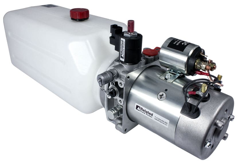
Bucher power up/gravity down pump with 6 qt poly tank. Port size is 3/8" NPT. Reservoir is 6.7" x 6.7" x 13". 1.25 gpm at 1,750 psi. Horizontal mount. Direct replacement for Light, Medium, and Heavy Duty dump kits.

We Use Cookies! Cookies make everything work well on our site. We understand if you don"t want to use them. However, many of the features are required to make the site work well. If you would like to not use these cookies, call us on our 1-800 number from a burner phone, place your order, then dispose of the phone after removing battery and disassembling.

KTI is a leader in Hydraulic Power Unit Manufacturing. They are well known for their Top Quality Construction and Building Units that have Low Noise Emissions.
All KTI hydraulics power units are 100% fully inspected to stringent test specifications. The tests ensure our customers they will receive a reliable, high-quality dump trailer power unit that will perform to our design specifications. KTI hydraulic pumps include a 2-year warranty.

The only complaint I have was with the packaging for shipment. One of the main bolts was missing. It appears that the mounting bolts and washers are installed then hand tightened. In my box, the bolt was missing but the 2 washers and nut were there. Another nut and washer had come off of a second bolt. The box was in pretty bad shape when it arrived, and I"m sure that missing bolt escaped that way. I blame UPS, not PJ. But nonetheless, I was missing a bolt. It might be a better practice for future shipments to place all hardware in a sealed bag and attach that bag to the bracket. Preferably with some shrink or Saran type wrap. But that"s just my suggestion.
Hydraulic pumps are mechanisms in hydraulic systems that move hydraulic fluid from point to point initiating the production of hydraulic power. Hydraulic pumps are sometimes incorrectly referred to as “hydrolic” pumps.
They are an important device overall in the hydraulics field, a special kind of power transmission which controls the energy which moving fluids transmit while under pressure and change into mechanical energy. Other kinds of pumps utilized to transmit hydraulic fluids could also be referred to as hydraulic pumps. There is a wide range of contexts in which hydraulic systems are applied, hence they are very important in many commercial, industrial, and consumer utilities.
“Power transmission” alludes to the complete procedure of technologically changing energy into a beneficial form for practical applications. Mechanical power, electrical power, and fluid power are the three major branches that make up the power transmission field. Fluid power covers the usage of moving gas and moving fluids for the transmission of power. Hydraulics are then considered as a sub category of fluid power that focuses on fluid use in opposition to gas use. The other fluid power field is known as pneumatics and it’s focused on the storage and release of energy with compressed gas.
"Pascal"s Law" applies to confined liquids. Thus, in order for liquids to act hydraulically, they must be contained within a system. A hydraulic power pack or hydraulic power unit is a confined mechanical system that utilizes liquid hydraulically. Despite the fact that specific operating systems vary, all hydraulic power units share the same basic components. A reservoir, valves, a piping/tubing system, a pump, and actuators are examples of these components. Similarly, despite their versatility and adaptability, these mechanisms work together in related operating processes at the heart of all hydraulic power packs.
The hydraulic reservoir"s function is to hold a volume of liquid, transfer heat from the system, permit solid pollutants to settle, and aid in releasing moisture and air from the liquid.
Mechanical energy is changed to hydraulic energy by the hydraulic pump. This is accomplished through the movement of liquid, which serves as the transmission medium. All hydraulic pumps operate on the same basic principle of dispensing fluid volume against a resistive load or pressure.
Hydraulic valves are utilized to start, stop, and direct liquid flow in a system. Hydraulic valves are made of spools or poppets and can be actuated hydraulically, pneumatically, manually, electrically, or mechanically.
The end result of Pascal"s law is hydraulic actuators. This is the point at which hydraulic energy is transformed back to mechanical energy. This can be accomplished by using a hydraulic cylinder to transform hydraulic energy into linear movement and work or a hydraulic motor to transform hydraulic energy into rotational motion and work. Hydraulic motors and hydraulic cylinders, like hydraulic pumps, have various subtypes, each meant for specific design use.
The essence of hydraulics can be found in a fundamental physical fact: fluids are incompressible. (As a result, fluids more closely resemble solids than compressible gasses) The incompressible essence of fluid allows it to transfer force and speed very efficiently. This fact is summed up by a variant of "Pascal"s Principle," which states that virtually all pressure enforced on any part of a fluid is transferred to every other part of the fluid. This scientific principle states, in other words, that pressure applied to a fluid transmits equally in all directions.
Furthermore, the force transferred through a fluid has the ability to multiply as it moves. In a slightly more abstract sense, because fluids are incompressible, pressurized fluids should keep a consistent pressure just as they move. Pressure is defined mathematically as a force acting per particular area unit (P = F/A). A simplified version of this equation shows that force is the product of area and pressure (F = P x A). Thus, by varying the size or area of various parts inside a hydraulic system, the force acting inside the pump can be adjusted accordingly (to either greater or lesser). The need for pressure to remain constant is what causes force and area to mirror each other (on the basis of either shrinking or growing). A hydraulic system with a piston five times larger than a second piston can demonstrate this force-area relationship. When a force (e.g., 50lbs) is exerted on the smaller piston, it is multiplied by five (e.g., 250 lbs) and transmitted to the larger piston via the hydraulic system.
Hydraulics is built on fluids’ chemical properties and the physical relationship between pressure, area, and force. Overall, hydraulic applications allow human operators to generate and exert immense mechanical force with little to no physical effort. Within hydraulic systems, both oil and water are used to transmit power. The use of oil, on the other hand, is far more common, owing in part to its extremely incompressible nature.
Pressure relief valves prevent excess pressure by regulating the actuators’ output and redirecting liquid back to the reservoir when necessary. Directional control valves are used to change the size and direction of hydraulic fluid flow.
While hydraulic power transmission is remarkably useful in a wide range of professional applications, relying solely on one type of power transmission is generally unwise. On the contrary, the most efficient strategy is to combine a wide range of power transmissions (pneumatic, hydraulic, mechanical, and electrical). As a result, hydraulic systems must be carefully embedded into an overall power transmission strategy for the specific commercial application. It is necessary to invest in locating trustworthy and skilled hydraulic manufacturers/suppliers who can aid in the development and implementation of an overall hydraulic strategy.
The intended use of a hydraulic pump must be considered when selecting a specific type. This is significant because some pumps may only perform one function, whereas others allow for greater flexibility.
The pump"s material composition must also be considered in the application context. The cylinders, pistons, and gears are frequently made of long-lasting materials like aluminum, stainless steel, or steel that can withstand the continuous wear of repeated pumping. The materials must be able to withstand not only the process but also the hydraulic fluids. Composite fluids frequently contain oils, polyalkylene glycols, esters, butanol, and corrosion inhibitors (though water is used in some instances). The operating temperature, flash point, and viscosity of these fluids differ.
In addition to material, manufacturers must compare hydraulic pump operating specifications to make sure that intended utilization does not exceed pump abilities. The many variables in hydraulic pump functionality include maximum operating pressure, continuous operating pressure, horsepower, operating speed, power source, pump weight, and maximum fluid flow. Standard measurements like length, rod extension, and diameter should be compared as well. Because hydraulic pumps are used in lifts, cranes, motors, and other heavy machinery, they must meet strict operating specifications.
It is critical to recall that the overall power generated by any hydraulic drive system is influenced by various inefficiencies that must be considered in order to get the most out of the system. The presence of air bubbles within a hydraulic drive, for example, is known for changing the direction of the energy flow inside the system (since energy is wasted on the way to the actuators on bubble compression). Using a hydraulic drive system requires identifying shortfalls and selecting the best parts to mitigate their effects. A hydraulic pump is the "generator" side of a hydraulic system that initiates the hydraulic procedure (as opposed to the "actuator" side that completes the hydraulic procedure). Regardless of disparities, all hydraulic pumps are responsible for displacing liquid volume and transporting it to the actuator(s) from the reservoir via the tubing system. Some form of internal combustion system typically powers pumps.
While the operation of hydraulic pumps is normally the same, these mechanisms can be split into basic categories. There are two types of hydraulic pumps to consider: gear pumps and piston pumps. Radial and axial piston pumps are types of piston pumps. Axial pumps produce linear motion, whereas radial pumps can produce rotary motion. The gear pump category is further subdivided into external gear pumps and internal gear pumps.
Each type of hydraulic pump, regardless of piston or gear, is either double-action or single-action. Single-action pumps can only pull, push, or lift in one direction, while double-action pumps can pull, push, or lift in multiple directions.
Vane pumps are positive displacement pumps that maintain a constant flow rate under varying pressures. It is a pump that self-primes. It is referred to as a "vane pump" because the effect of the vane pressurizes the liquid.
This pump has a variable number of vanes mounted onto a rotor that rotates within the cavity. These vanes may be variable in length and tensioned to maintain contact with the wall while the pump draws power. The pump also features a pressure relief valve, which prevents pressure rise inside the pump from damaging it.
Internal gear pumps and external gear pumps are the two main types of hydraulic gear pumps. Pumps with external gears have two spur gears, the spurs of which are all externally arranged. Internal gear pumps also feature two spur gears, and the spurs of both gears are internally arranged, with one gear spinning around inside the other.
Both types of gear pumps deliver a consistent amount of liquid with each spinning of the gears. Hydraulic gear pumps are popular due to their versatility, effectiveness, and fairly simple design. Furthermore, because they are obtainable in a variety of configurations, they can be used in a wide range of consumer, industrial, and commercial product contexts.
Hydraulic ram pumps are cyclic machines that use water power, also referred to as hydropower, to transport water to a higher level than its original source. This hydraulic pump type is powered solely by the momentum of moving or falling water.
Ram pumps are a common type of hydraulic pump, especially among other types of hydraulic water pumps. Hydraulic ram pumps are utilized to move the water in the waste management, agricultural, sewage, plumbing, manufacturing, and engineering industries, though only about ten percent of the water utilized to run the pump gets to the planned end point.
Despite this disadvantage, using hydropower instead of an external energy source to power this kind of pump makes it a prominent choice in developing countries where the availability of the fuel and electricity required to energize motorized pumps is limited. The use of hydropower also reduces energy consumption for industrial factories and plants significantly. Having only two moving parts is another advantage of the hydraulic ram, making installation fairly simple in areas with free falling or flowing water. The water amount and the rate at which it falls have an important effect on the pump"s success. It is critical to keep this in mind when choosing a location for a pump and a water source. Length, size, diameter, minimum and maximum flow rates, and speed of operation are all important factors to consider.
Hydraulic water pumps are machines that move water from one location to another. Because water pumps are used in so many different applications, there are numerous hydraulic water pump variations.
Water pumps are useful in a variety of situations. Hydraulic pumps can be used to direct water where it is needed in industry, where water is often an ingredient in an industrial process or product. Water pumps are essential in supplying water to people in homes, particularly in rural residences that are not linked to a large sewage circuit. Water pumps are required in commercial settings to transport water to the upper floors of high rise buildings. Hydraulic water pumps in all of these situations could be powered by fuel, electricity, or even by hand, as is the situation with hydraulic hand pumps.
Water pumps in developed economies are typically automated and powered by electricity. Alternative pumping tools are frequently used in developing economies where dependable and cost effective sources of electricity and fuel are scarce. Hydraulic ram pumps, for example, can deliver water to remote locations without the use of electricity or fuel. These pumps rely solely on a moving stream of water’s force and a properly configured number of valves, tubes, and compression chambers.
Electric hydraulic pumps are hydraulic liquid transmission machines that use electricity to operate. They are frequently used to transfer hydraulic liquid from a reservoir to an actuator, like a hydraulic cylinder. These actuation mechanisms are an essential component of a wide range of hydraulic machinery.
There are several different types of hydraulic pumps, but the defining feature of each type is the use of pressurized fluids to accomplish a job. The natural characteristics of water, for example, are harnessed in the particular instance of hydraulic water pumps to transport water from one location to another. Hydraulic gear pumps and hydraulic piston pumps work in the same way to help actuate the motion of a piston in a mechanical system.
Despite the fact that there are numerous varieties of each of these pump mechanisms, all of them are powered by electricity. In such instances, an electric current flows through the motor, which turns impellers or other devices inside the pump system to create pressure differences; these differential pressure levels enable fluids to flow through the pump. Pump systems of this type can be utilized to direct hydraulic liquid to industrial machines such as commercial equipment like elevators or excavators.
Hydraulic hand pumps are fluid transmission machines that utilize the mechanical force generated by a manually operated actuator. A manually operated actuator could be a lever, a toggle, a handle, or any of a variety of other parts. Hydraulic hand pumps are utilized for hydraulic fluid distribution, water pumping, and various other applications.
Hydraulic hand pumps may be utilized for a variety of tasks, including hydraulic liquid direction to circuits in helicopters and other aircraft, instrument calibration, and piston actuation in hydraulic cylinders. Hydraulic hand pumps of this type use manual power to put hydraulic fluids under pressure. They can be utilized to test the pressure in a variety of devices such as hoses, pipes, valves, sprinklers, and heat exchangers systems. Hand pumps are extraordinarily simple to use.
Each hydraulic hand pump has a lever or other actuation handle linked to the pump that, when pulled and pushed, causes the hydraulic liquid in the pump"s system to be depressurized or pressurized. This action, in the instance of a hydraulic machine, provides power to the devices to which the pump is attached. The actuation of a water pump causes the liquid to be pulled from its source and transferred to another location. Hydraulic hand pumps will remain relevant as long as hydraulics are used in the commerce industry, owing to their simplicity and easy usage.
12V hydraulic pumps are hydraulic power devices that operate on 12 volts DC supplied by a battery or motor. These are specially designed processes that, like all hydraulic pumps, are applied in commercial, industrial, and consumer places to convert kinetic energy into beneficial mechanical energy through pressurized viscous liquids. This converted energy is put to use in a variety of industries.
Hydraulic pumps are commonly used to pull, push, and lift heavy loads in motorized and vehicle machines. Hydraulic water pumps may also be powered by 12V batteries and are used to move water out of or into the desired location. These electric hydraulic pumps are common since they run on small batteries, allowing for ease of portability. Such portability is sometimes required in waste removal systems and vehiclies. In addition to portable and compact models, options include variable amp hour productions, rechargeable battery pumps, and variable weights.
While non rechargeable alkaline 12V hydraulic pumps are used, rechargeable ones are much more common because they enable a continuous flow. More considerations include minimum discharge flow, maximum discharge pressure, discharge size, and inlet size. As 12V batteries are able to pump up to 150 feet from the ground, it is imperative to choose the right pump for a given use.
Air hydraulic pumps are hydraulic power devices that use compressed air to stimulate a pump mechanism, generating useful energy from a pressurized liquid. These devices are also known as pneumatic hydraulic pumps and are applied in a variety of industries to assist in the lifting of heavy loads and transportation of materials with minimal initial force.
Air pumps, like all hydraulic pumps, begin with the same components. The hydraulic liquids, which are typically oil or water-based composites, require the use of a reservoir. The fluid is moved from the storage tank to the hydraulic cylinder via hoses or tubes connected to this reservoir. The hydraulic cylinder houses a piston system and two valves. A hydraulic fluid intake valve allows hydraulic liquid to enter and then traps it by closing. The discharge valve is the point at which the high pressure fluid stream is released. Air hydraulic pumps have a linked air cylinder in addition to the hydraulic cylinder enclosing one end of the piston.
The protruding end of the piston is acted upon by a compressed air compressor or air in the cylinder. When the air cylinder is empty, a spring system in the hydraulic cylinder pushes the piston out. This makes a vacuum, which sucks fluid from the reservoir into the hydraulic cylinder. When the air compressor is under pressure, it engages the piston and pushes it deeper into the hydraulic cylinder and compresses the liquids. This pumping action is repeated until the hydraulic cylinder pressure is high enough to forcibly push fluid out through the discharge check valve. In some instances, this is connected to a nozzle and hoses, with the important part being the pressurized stream. Other uses apply the energy of this stream to pull, lift, and push heavy loads.
Hydraulic piston pumps transfer hydraulic liquids through a cylinder using plunger-like equipment to successfully raise the pressure for a machine, enabling it to pull, lift, and push heavy loads. This type of hydraulic pump is the power source for heavy-duty machines like excavators, backhoes, loaders, diggers, and cranes. Piston pumps are used in a variety of industries, including automotive, aeronautics, power generation, military, marine, and manufacturing, to mention a few.
Hydraulic piston pumps are common due to their capability to enhance energy usage productivity. A hydraulic hand pump energized by a hand or foot pedal can convert a force of 4.5 pounds into a load-moving force of 100 pounds. Electric hydraulic pumps can attain pressure reaching 4,000 PSI. Because capacities vary so much, the desired usage pump must be carefully considered. Several other factors must also be considered. Standard and custom configurations of operating speeds, task-specific power sources, pump weights, and maximum fluid flows are widely available. Measurements such as rod extension length, diameter, width, and height should also be considered, particularly when a hydraulic piston pump is to be installed in place of a current hydraulic piston pump.
Hydraulic clutch pumps are mechanisms that include a clutch assembly and a pump that enables the user to apply the necessary pressure to disengage or engage the clutch mechanism. Hydraulic clutches are crafted to either link two shafts and lock them together to rotate at the same speed or detach the shafts and allow them to rotate at different speeds as needed to decelerate or shift gears.
Hydraulic pumps change hydraulic energy to mechanical energy. Hydraulic pumps are particularly designed machines utilized in commercial, industrial, and residential areas to generate useful energy from different viscous liquids pressurization. Hydraulic pumps are exceptionally simple yet effective machines for moving fluids. "Hydraulic" is actually often misspelled as "Hydralic". Hydraulic pumps depend on the energy provided by hydraulic cylinders to power different machines and mechanisms.
There are several different types of hydraulic pumps, and all hydraulic pumps can be split into two primary categories. The first category includes hydraulic pumps that function without the assistance of auxiliary power sources such as electric motors and gas. These hydraulic pump types can use the kinetic energy of a fluid to transfer it from one location to another. These pumps are commonly called ram pumps. Hydraulic hand pumps are never regarded as ram pumps, despite the fact that their operating principles are similar.
The construction, excavation, automotive manufacturing, agriculture, manufacturing, and defense contracting industries are just a few examples of operations that apply hydraulics power in normal, daily procedures. Since hydraulics usage is so prevalent, hydraulic pumps are unsurprisingly used in a wide range of machines and industries. Pumps serve the same basic function in all contexts where hydraulic machinery is used: they transport hydraulic fluid from one location to another in order to generate hydraulic energy and pressure (together with the actuators).
Elevators, automotive brakes, automotive lifts, cranes, airplane flaps, shock absorbers, log splitters, motorboat steering systems, garage jacks and other products use hydraulic pumps. The most common application of hydraulic pumps in construction sites is in big hydraulic machines and different types of "off-highway" equipment such as excavators, dumpers, diggers, and so on. Hydraulic systems are used in other settings, such as offshore work areas and factories, to power heavy machinery, cut and bend material, move heavy equipment, and so on.
Fluid’s incompressible nature in hydraulic systems allows an operator to make and apply mechanical power in an effective and efficient way. Practically all force created in a hydraulic system is applied to the intended target.
Because of the relationship between area, pressure, and force (F = P x A), modifying the force of a hydraulic system is as simple as changing the size of its components.
Hydraulic systems can transfer energy on an equal level with many mechanical and electrical systems while being significantly simpler in general. A hydraulic system, for example, can easily generate linear motion. On the contrary, most electrical and mechanical power systems need an intermediate mechanical step to convert rotational motion to linear motion.
Hydraulic systems are typically smaller than their mechanical and electrical counterparts while producing equivalents amounts of power, providing the benefit of saving physical space.
Hydraulic systems can be used in a wide range of physical settings due to their basic design (a pump attached to actuators via some kind of piping system). Hydraulic systems could also be utilized in environments where electrical systems would be impractical (for example underwater).
By removing electrical safety hazards, using hydraulic systems instead of electrical power transmission improves relative safety (for example explosions, electric shock).
The amount of power that hydraulic pumps can generate is a significant, distinct advantage. In certain cases, a hydraulic pump could generate ten times the power of an electrical counterpart. Some hydraulic pumps (for example, piston pumps) cost more than the ordinary hydraulic component. These drawbacks, however, can be mitigated by the pump"s power and efficiency. Despite their relatively high cost, piston pumps are treasured for their strength and capability to transmit very viscous fluids.
Handling hydraulic liquids is messy, and repairing leaks in a hydraulic pump can be difficult. Hydraulic liquid that leaks in hot areas may catch fire. Hydraulic lines that burst may cause serious injuries. Hydraulic liquids are corrosive as well, though some are less so than others. Hydraulic systems need frequent and intense maintenance. Parts with a high factor of precision are frequently required in systems. If the power is very high and the pipeline cannot handle the power transferred by the liquid, the high pressure received by the liquid may also cause work accidents.
Even though hydraulic systems are less complex than electrical or mechanical systems, they are still complex systems that should be handled with caution. Avoiding physical contact with hydraulic systems is an essential safety precaution when engaging with them. Even when a hydraulic machine is not in use, active liquid pressure within the system can be a hazard.
Inadequate pumps can cause mechanical failure in the place of work that can have serious and costly consequences. Although pump failure has historically been unpredictable, new diagnostic technology continues to improve on detecting methods that previously relied solely on vibration signals. Measuring discharge pressures enables manufacturers to forecast pump wear more accurately. Discharge sensors are simple to integrate into existing systems, increasing the hydraulic pump"s safety and versatility.
Hydraulic pumps are devices in hydraulic systems that move hydraulic fluid from point to point, initiating hydraulic power production. They are an important device overall in the hydraulics field, a special kind of power transmission that controls the energy which moving fluids transmit while under pressure and change into mechanical energy. Hydraulic pumps are divided into two categories namely gear pumps and piston pumps. Radial and axial piston pumps are types of piston pumps. Axial pumps produce linear motion, whereas radial pumps can produce rotary motion. The construction, excavation, automotive manufacturing, agriculture, manufacturing, and defense contracting industries are just a few examples of operations that apply hydraulics power in normal, daily procedures.

The hydraulic pump is designed to be mounted horizontally or vertically – sight glass and dip stick can be switched on the round steel tank depending on the mounting direction of the pump to facilitate proper use. Dual location oil drain plugs are in easy to access positions regardless of pump orientation.
12-volt DC, 2 kW, 200-amp pump with sealed solenoid connections, to eliminate potential corrosion, produces an adjustable pressure up to 3200 PSI. 20-foot-long detachable pendant control has a magnetic base to easily attach to any metal location. Wires are protected with an all-weather jacket.

In aviation, a power transfer unit (PTU) is a device that transfers hydraulic power from one of an aircraft"s hydraulic systems to another in the event that second system has failed or been turned off.
The PTU is used when, for example, there is right hydraulic system pressure but no left hydraulic system pressure. In this example, the PTU transfers hydraulic power from the right hydraulic system to the left hydraulic system. A PTU consists of a hydraulic motor paired with a hydraulic pump via a shaft.
Large transport category aircraft with hydraulically powered flight controls and utilities typically have multiple, independent hydraulic systems powered by a combination of engine-driven and electrically driven hydraulic pumps. Multiple hydraulic systems are typically needed for redundancy, where for instance if one system fails or loses hydraulic fluid, a surviving system may still provide sufficient power for critical systems to continue safe flight and landing.
On airliners or business jets with powered flight controls, it is typical to have at least two hydraulic power control units (actuators) for each critical flight control surface — these are the elevators, rudder and ailerons. Only two sources might be used if some form of mechanical reversion is present (i.e. the pilot can still fly the aeroplane manually, but with some difficulty, via mechanical linkages and cables if hydraulic power is lost).
On fly-by-wire aircraft, at least three independent power sources are needed. Spoilers and flaps meanwhile are considered secondary flight controls, and may only have a single hydraulic power source, providing the flight control can be deployed symmetrically.
Likewise, landing gear, brakes and nosewheel steering are systems which are not considered critical for flight, and subsequently they are typically only powered by a single hydraulic system on an airliner or business jet.
Where an aircraft utility is powered by a single hydraulic system, PTUs become beneficial in allowing a single source of power, e.g. a pump powered by one surviving engine, to power more than one hydraulic system if the source of power in that system has failed. PTUs only work on the proviso that the system has not punctured and lost its fluid, because they do not permit fluid transfer, only the transfer of mechanical work.
For example, on the original design of the Airbus A320, the landing gear hydraulics (extension/retraction, brakes and steering) were solely powered from the Green (left hand) system, powered by the left-hand engine driven pump. In the event of a port engine failure during take-off, the landing gear would not be able to retract as there is no auxiliary motorpump in the green hydraulic system on an A320. (Modern A320s have the nose wheel steering powered by the yellow system.)
The PTU solves this problem by allowing a rotary mechanical coupling between both systems, so the engine driven pump for the Yellow (right hand) system on the starboard engine, which is oversized for normal hydraulic demand, can dump the excess power into the green system via the PTU, and allow powered landing gear retraction to continue, while maintaining hydraulic pressure to the green system flight controls as well.
Assuring landing gear retraction in a failure case is one potential assurance provided by a PTU. Alternatively, the designer may elect to have a second electric motorpump perform this role if a PTU is not desired. An additional motorpump may be heavier than a PTU however, and complex trade studies may favour one option or the other, depending which failure cases you consider and how important weight is in the trade-off.
On the Airbus A320 the Yellow system may power the Green system, but because it is also bi-directional, if the starboard engine fails, the Green system can help to power the yellow system by dumping excess power into it via the same mechanism. This is also known as a "reversible" PTU.
On some other aircraft the directional of rotation of the PTU, and thereby the fluid flow through it, may be designed to work in only one direction. The Citation X business jet is one such aircraft with a uni-directional PTU protected by check-vales and a back-pressure stall line, designed to allow the right hand hydraulic system to assist the left hand hydraulic system and left hand auxiliary motorpump to retract the landing gear during a Port engine failure only.
On yet other aircraft, the function of a bi-directional reversible PTU can be accomplished with two uni-directional PTUs installed side-by-side arranged in opposite orientations to each other. The hydraulic system of the CH-47 Chinook helicopter uses twin uni-directional PTUs in this fashion.
Hydraulic power transfer units are essentially nothing more than a hydraulic motor coupled to a hydraulic pump via a shaft, as such conceptually they can be any kind of motor or pump such as vane, gear, impeller or in-line piston types, or variable displacement in-line piston types.
A straight-axis in-line piston pump/motor relies on a canted internal swashplate to drive the piston shoes up and down around the internal piston slipway of the pump, lubricated by the fluid itself — this kind of PTU may appear to resemble two cylinders bolted together, with an inlet and outlet port at either end. An example of a straight axis in-line PTU can be found in the Cessna Citation X hydraulic system.
A bent axis in-line piston pump works the same way, but forgoes the canted swashplate, instead the whole rotating group is tilted to achieve the piston displacement.
In yet further representations, a bent axis fixed-displacement motor/pump can be mated with a straight axis variable displacement motorpump, as in the case of the Airbus A320 PTU.
The mechanism by which a PTU works is by surging, PTUs self-start by pure mechanical influence alone resulting from the delta-pressure between the two hydraulic systems it is connected to. Consequently, a PTU accelerates very rapidly under the delta-P induced load, and then stops just as suddenly once the pressure equalizes. Each pressure surge may only be a second long, causing a stop-start mode of operation.
Passengers who have flown on the Airbus A320 will frequently hear the PTU "barking dog", generally when only one engine is running, or when the Yellow system electric motorpump is the only active hydraulic power source, the PTU is mechanically activated. Consequently, normally the PTU is only heard on start-up or shut down. Very rarely is it heard in flight unless a momentary power deficit is present when retracting the gear, or a hydraulic fault has occurred.
In Airbus literature, it is stated that the PTU "self-tests", on startup, however the PTU does not contain any electronic motor assistance and cannot be commanded to start, it starts by itself only when hydraulic pressure is present. However, solenoid energized shut-off valves can isolate the PTU via a push-button switch (pb/sw) in the cockpit, but this feature is rarely used.
Since their invention,hydraulic forkliftshave helped people get difficult, heavy work done. If you are a heavy equipment operator, it’s important to understand how these forces work and the different parts that go into them.
Understandinghow a forklift hydraulic system worksis simpler than you might expect. It all depends on specialpressurized fluidusedto power the engine of a car or machine. Hydraulic presses put pressure on a small amount of liquid to create a large amount of power.
Confined liquid has pressure on it from one side. That pressure forces the liquid against a piston on the other side of the container. That transfers energy into the piston, forcing it upward. The piston cannot move in the opposite direction unless the pressure is released. In terms of theforklift hydraulicsystem, the pistons raise the forks and keep them lifted until the hydraulic pressure is released by the operator.
Produces a constant flow of hydraulic fluid to supply the control valve. Most forklifts use a gear-type pump. The pump consists of a pair of rotating gears that push the fluid in the opposite direction of the rotation.
Starts and stops the direction of fluid and controls where the fluid moves using spools. Without a control valve, forklift hydraulic pressure would be useless.
The types of fluids used inhydraulic forkliftsinclude water-based fluids, petroleum-based fluids, and synthetic fluids. Water-based fluids are fire-resistant but do not provide as much lubrication as the other types. Petroleum-based fluids are customized to the hydraulic system with additives and are the most popular. Synthetic fluids are useful for high temperature and high-pressure systems.
If you’ve ever put your finger over a hose while it’s running at full blast, you’ve experienced the power of hydraulic pressure. The same principle is at work inforklift hydraulics. While air can be compressed, liquids cannot, so when you exert pressure in a confined space, you create hydraulic pressure.
Giant pistons on the front of forklifts are responsible for hydraulic pressure. They’re fed by fluid hoses with a high pressure pump at the end. They supply the pressure necessary to move hydraulic fluid through the system and move pistons up and down.
What happens when there is a very heavy load for the forklift to lift? That’s when the Flow Divider comes into play. It can split one line of fluid into two, three, or more. By splitting or recombining the hydraulic line, the force can be increased or decreased. The hydraulic pump exerts a finite amount of pressure, but each load requires a different amount of pressure, so the flow divider can reduce the pressure by diverting fluid back into the reservoir, or increase it by sending all the fluid through to the cylinders.
Another crucial part of the system is the Return Filter, which is exactly what it sounds like. It cleans theforklift hydraulic fluidof any contaminants before it goes back into the reservoir.
Forklift hydraulics raise the load-bearing prongs off the ground. Ahydraulic forkliftlifts and holds the load in the air while the forklift moves. A forklift hydraulic system is the heart of the machine because it is responsible for moving pallets. And the heart of your company’s safety program is proper hydraulic forklift training and certification! The levers control the hydraulic system in a forklift. The operator needs to be very careful with them. It’s important that only trained and certified operators use forklifts. They need to properly calculate the load and how much lift power is needed to move it. The hydraulics of a forklift have a lot of power, and only a small amount of effort can create enough force to move a large, heavy load.
The proper usage andmaintenance of a forkliftwill keep the forklift hydraulic pressure system in good working condition, without needing constant repair work.
French scientist Blaise Pascal discovered the principle behind the hydraulic system over 300 years ago. Pascal learned that liquid cannot be compressed. When pressure is put on a confined liquid, the liquid transmits pressure in all directions. Those are the basic principles behind the forklift hydraulic pressure system. For example, if a container holding liquid has an opening, the liquid will try to escape at a pressure that’s equal to the pressure put into the container.
In the late 1700s, British mechanic and engineer, Joseph Bramah, used Pascal’s principles to experiment on practical applications. In 1795, Bramah patented the first hydraulic press which became the basis for the modern-day hydraulic system.
To determine which grade of hydraulic fluid a forklift uses, consult the lift’s operations manual. Here, you can find full details about the proper type of hydraulic fluid for a forklift, how often the fluid should be changed, and other pertinent information. If you cannot find the lift’s operations manual, use a general purpose fluid like ISO 32 hydraulic oil.
When it comes to hydraulic fluid for a forklift, stick to the recommendation included in the lift’s operations manual. Using the proper hydraulic fluid limits the risk of wear and tear on your lift.
Forklift hydraulic fluidmust be regularly topped up for maximum effectiveness. Locate the hydraulic reservoir on your lift. It should have a vented fill cap with a fill gauge or sight glass on the side to indicate fluid level. Remove the cap and then pour in the oil and begin pumping the liquid into the reservoir. Keep an eye on the levels; once the oil reaches the maximum fill line, you can stop pumping. Remove the fill nozzle and replace the cap.
To fully comprehend the power ofhydraulic forklifts, it helps to understand Pascal’s Law. It explains how force changes pressure. To calculate the hydraulic advantage of your particular lift, understand that the force exerted is equal to the pump pressure multiplied by the surface area of thehydraulic fluid cylinder. For instance, a system with 1000psi pushing against a cylinder with a surface area of 10 inches provides forces of up to 10,000 pounds.
Mast drift occurs when a lift’s mast changes position when elevated under load. The problem may seem minor at first. However, when left unaddressed, the issue can escalate quickly and cause a lift to tip over.
Hydraulic system hoses are used to transfer fluid pressure. But, a hose deteriorates over time, and it can crack and leak. Other factors that can cause a hose to crack or leak include the use of an improperly fitted hose fitting or use of an incompatible type of hydraulic fluid.
A suction filter can become clogged if it goes unchanged for an extended period of time. In this instance, the filter can no longer catch and remove contaminants from the hydraulic fluid. It can also stop the flow of hydraulic fluid.
At the first sign of anyhydraulic forkliftproblems, it is beneficial to diagnose and address these issues. This ensures that a forklift can be fixed or replaced before it can potentially put the health and wellbeing of lift operators in danger.
You don’t have to be an expert onhydraulic forkliftsto know thatwell-trained driversare essential for workplace safety. Whether your warehouse runs electric lifts or hydraulic forklifts,CertifyMe.netis your #1 source for OSHA compliant training and certification.
Even if you don’t know how ahydraulic forkliftsystem works, that’s OK – we’ll explain all the critical safety concepts so your employees can avoid accidents. Gain the peace of mind that comes with completeOSHA certificationand sign up for our hydraulic forklift training programs today!
Operator training will keep all workers safe in the vicinity of the forklift, and ensure that operators have the proper understanding of how the hydraulic system works and how it is used most effectively.
Check out the online forklift training fromCertifyMe.netfor the most convenient and comprehensive forklift training available. Operators learn how to run a forklift, perform equipment inspections and operate the forklift hydraulic pressure system correctly. Sign up today for same-day certifications!Have questions about our certification opportunities or want to speak with our team?Reach out online

An essential requirement for the optimum performance and service life of a hydraulic pump is that its pumping chambers fill freely and completely during intake. So if getting maximum pump life is your primary concern (and it should be), then anything that makes the free and complete filling of the pump"s chambers more difficult to achieve should be avoided.
Suction strainers and most other forms of inlet filtration are a common culprit. With rare exceptions, a suction strainer has no place in a properly designed and properly maintained hydraulic system.
But when you take a position against the majority, there will be many who disagree with you. And so I regularly hear from folks who feel they need to explain to me why their hydraulic system is different and why they have no alternative but to use this pump-killing device.
I prefer not to debate the point with people who have convinced themselves of the merits of suction strainers or, in some cases, use them as a substitute for proper design. I refer them to the pump manufacturer"s recommendation instead. Here is an excerpt from a Rexroth Hydraulics manual1 that dates back to 1979:
"The advantages of suction filtration are strongly outweighed by the disadvantage of the pressure drop created by the element. … Any benefit the suction filter offers by keeping contamination out of the pump is offset by the possibility of damaging the pump because of cavitation. …
"Another major disadvantage of the suction strainer is that it is located inside the oil reservoir, which makes it inconvenient to service. It is for this reason that many suction strainers in hydraulic systems go unserviced until they starve the pump and cause cavitation damage. ... Due to these disadvantages … filtration at the inlet of the pump is specifically not recommended."
It speaks volumes about the hydraulics industry that this 30-year-old advice from a leading hydraulic pump manufacturer is still widely ignored today. But a suction strainer isn"t the only "engineered in" barrier to the free and complete filling of the pump. Another is mounting the pump above the tank or, more precisely, above minimum oil level. In other words, making the pump "lift" the oil into its intake.
According to most manufacturers, mounting the pump above minimum oil level is an approved mounting position for many pump designs. "Approved" means that the manufacturer says it"s OK to do it. But approved does not mean it maximizes pump service life. That is because making the pump lift its oil does the opposite. This is particularly true for piston and vane pumps, which due to their design do not cope well with vacuum-induced forces.
Pump inlet conditions also affect noise and heat load. When exposed to atmospheric pressure at room temperature, mineral hydraulic oil contains between 6 and 12 percent of dissolved air by volume. If the pressure on the oil is reduced to less than atmospheric pressure - due to restriction in the pump intake or required lift - this air expands and becomes a greater percentage of the volume.
These expanding gas bubbles at the pump inlet collapse as the pumping chamber is exposed to system pressure (gaseous cavitation). The result is heat generation and noise. The larger the air bubble, the greater the noise level and heat generated. If the absolute pressure at the pump intake continues to fall (higher vacuum), the oil can start to change state from a liquid to a gas - known as vaporous cavitation.
For these reasons, the perfect pump inlet condition is 100 percent boost. This means that, ideally, you want the pump inlet to be supercharged under all operating conditions.
While supercharging the pump inlet is not practical in most applications, there is virtually no excuse for not having a flooded inlet. A flooded inlet means there"s a head of oil above the pump. In other words, the pump is mounted in such a way that its intake is below minimum oil level (Figure 1).
In the case of industrial power units, this rules out mounting the pump on top of the tank (Figure 2). And in most cases, it will rule out mounting the pump inside the tank - with the electric motor mounted vertically (Figure 3) — unless the pump is submerged to a depth where its inlet port is below minimum oil level (without the need to install a drop tube on the intake).
Besides making the pump lift its oil, both of these mounting positions (figures 2 and 3) make maintenance extremely difficult - with having the pump inside the tank being the worst. But unfortunately for the owners of this equipment, mounting the pump inside the tank has almost become standard practice for electric power units because it is a cheap and easy method of construction.
If you"ve been reading my column in Machinery Lubrication for a while, you"re probably already familiar with the problems associated with suction strainers. But unlike a suction strainer, which is easily removed, pump mounting position is not easy to change. So, what can be done about it?
Well, if you"re a hydraulic equipment user, specify that the pump must have a flooded inlet for all of your future equipment purchases. And if you design or manufacture hydraulic power units, do your customers (and your machine"s reliability) a favor: ensure all your hydraulic power units feature a flooded inlet.


 8613371530291