
primary mover hydraulic pump factory

We provide a variety of high-quality single and double-acting 12V hydraulic pumps. Choose from a selection of poly or steel reservoir sizing options. Our pumps are ideal for application with Dump Trailers and more. Browse our shop today and find the right hydraulic pump for your hydraulic circuit needs!
The prime mover supplies the mechanical power to drive the hydraulic system. In the mobile hydraulics industry the prime mover we are most familiar with is the truck engine. The truck engine is frequently used to provide power through a Power Take-Off, through belts from the crankshaft pulley, or directly through a tubular driveshaft assembly. On some high horsepower systems an auxiliary, or “pony” engine might be used. In any case, the prime mover must be capable of providing the horsepower necessary to power the hydraulic system.
Double, or Triple Gear, power take-offs, found on dump trucks, refuse vehicles, wreckers, aerial bucket trucks, tank trucks, and truck mounted cranes, are the most widely used type of PTO because of their versatility. This type of PTO can be engaged by cable, air, electric solenoid, or mechanical levers and a wide variety of output shafts and mounting flanges allow for direct coupling of hydraulic pumps from major manufacturers. PTO output shaft speeds can be changed by changing the internal gear ratio of the PTO.
We will not attempt to go into PTO selection in this text. Suffice to say that when a power take-off is utilized as the source of power for the hydraulic system, it must meet the torque, horsepower, and speed requirements of the system.
Many refuse and snow control vehicles utilize a front-mounted hydraulic pump driven by a tubular driveshaft assembly from the harmonic balancer of the engine. This “live power” arrangement has the advantage of providing full engine torque on high-demand applications while eliminating the cost of the power take-off. The disadvantage to this type of installation is in the requirement to raise, or “core”, the radiator to allow passage for the driveshaft; extend the front frame rails; and fabricate a mounting bracket for the pump.
Another important consideration is driveshaft angularity. Not only is it necessary to keep the angle shallow—generally less than 7°—but also to keep the pump input shaft parallel to the engine crankshaft within 1-1/2°. Likewise, the yokes on each end of the shaft must be “in phase”, or aligned with each other. Failure to address any of these requirements will result in driveshaft vibration and damage to the pump.

There are typically three types of hydraulic pump constructions found in mobile hydraulic applications. These include gear, piston, and vane; however, there are also clutch pumps, dump pumps, and pumps for refuse vehicles such as dry valve pumps and Muncie Power Products’ Live PakTM.
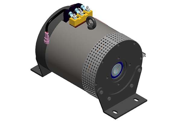
The hydraulic pump is the component of the hydraulic system that takes mechanical energy and converts it into fluid energy in the form of oil flow. This mechanical energy is taken from what is called the prime mover (a turning force) such as the power take-off or directly from the truck engine.
With each hydraulic pump, the pump will be of either a uni-rotational or bi-rotational design. As its name implies, a uni-rotational pump is designed to operate in one direction of shaft rotation. On the other hand, a bi-rotational pump has the ability to operate in either direction.
For truck-mounted hydraulic systems, the most common design in use is the gear pump. This design is characterized as having fewer moving parts, being easy to service, more tolerant of contamination than other designs and relatively inexpensive. Gear pumps are fixed displacement, also called positive displacement, pumps. This means the same volume of flow is produced with each rotation of the pump’s shaft. Gear pumps are rated in terms of the pump’s maximum pressure rating, cubic inch displacement and maximum input speed limitation.
Generally, gear pumps are used in open center hydraulic systems. Gear pumps trap oil in the areas between the teeth of the pump’s two gears and the body of the pump, transport it around the circumference of the gear cavity and then force it through the outlet port as the gears mesh. Behind the brass alloy thrust plates, or wear plates, a small amount of pressurized oil pushes the plates tightly against the gear ends to improve pump efficiency.
A cylinder block containing pistons that move in and out is housed within a piston pump. It’s the movement of these pistons that draw oil from the supply port and then force it through the outlet. The angle of the swash plate, which the slipper end of the piston rides against, determines the length of the piston’s stroke. While the swash plate remains stationary, the cylinder block, encompassing the pistons, rotates with the pump’s input shaft. The pump displacement is then determined by the total volume of the pump’s cylinders. Fixed and variable displacement designs are both available.
With a fixed displacement piston pump, the swash plate is nonadjustable. Its proportional output flow to input shaft speed is like that of a gear pump and like a gear pump, the fixed displacement piston pump is used within open center hydraulic systems.
As previously mentioned, piston pumps are also used within applications like snow and ice control where it may be desirable to vary system flow without varying engine speed. This is where the variable displacement piston pump comes into play – when the hydraulic flow requirements will vary based on operating conditions. Unlike the fixed displacement design, the swash plate is not fixed and its angle can be adjusted by a pressure signal from the directional valve via a compensator.
Vane pumps were, at one time, commonly used on utility vehicles such as aerial buckets and ladders. Today, the vane pump is not commonly found on these mobile (truck-mounted) hydraulic systems as gear pumps are more widely accepted and available.
Within a vane pump, as the input shaft rotates it causes oil to be picked up between the vanes of the pump which is then transported to the pump’s outlet side. This is similar to how gear pumps work, but there is one set of vanes – versus a pair of gears – on a rotating cartridge in the pump housing. As the area between the vanes decreases on the outlet side and increases on the inlet side of the pump, oil is drawn in through the supply port and expelled through the outlet as the vane cartridge rotates due to the change in area.
Input shaft rotates, causing oil to be picked up between the vanes of the pump which is then transported to pump outlet side as area between vanes decreases on outlet side and increases on inlet side to draw oil through supply port and expel though outlet as vane cartridge rotates
A clutch pump is a small displacement gear pump equipped with a belt-driven, electromagnetic clutch, much like that found on a car’s air conditioner compressor. It is engaged when the operator turns on a switch inside the truck cab. Clutch pumps are frequently used where a transmission power take-off aperture is not provided or is not easily accessible. Common applications include aerial bucket trucks, wreckers and hay spikes. As a general rule clutch pumps cannot be used where pump output flows are in excess of 15 GPM as the engine drive belt is subject to slipping under higher loads.
What separates this pump from the traditional gear pump is its built-in pressure relief assembly and an integral three-position, three-way directional control valve. The dump pump is unsuited for continuous-duty applications because of its narrow, internal paths and the subsequent likelihood of excessive heat generation.
Dump pumps are often direct mounted to the power take-off; however, it is vital that the direct-coupled pumps be rigidly supported with an installer-supplied bracket to the transmission case with the pump’s weight at 70 lbs. With a dump pump, either a two- or three-line installation must be selected (two-line and three-line refer to the number of hoses used to plumb the pump); however, a dump pump can easily be converted from a two- to three-line installation. This is accomplished by inserting an inexpensive sleeve into the pump’s inlet port and uncapping the return port.
Many dump bodies can function adequately with a two-line installation if not left operating too long in neutral. When left operating in neutral for too long however, the most common dump pump failure occurs due to high temperatures. To prevent this failure, a three-line installation can be selected – which also provides additional benefits.
Pumps for refuse equipment include both dry valve and Live Pak pumps. Both conserve fuel while in the OFF mode, but have the ability to provide full flow when work is required. While both have designs based on that of standard gear pumps, the dry valve and Like Pak pumps incorporate additional, special valving.
Primarily used on refuse equipment, dry valve pumps are large displacement, front crankshaft-driven pumps. The dry valve pump encompasses a plunger-type valve in the pump inlet port. This special plunger-type valve restricts flow in the OFF mode and allows full flow in the ON mode. As a result, the horsepower draw is lowered, which saves fuel when the hydraulic system is not in use.
In the closed position, the dry valve allows just enough oil to pass through to maintain lubrication of the pump. This oil is then returned to the reservoir through a bleed valve and small return line. A bleed valve that is fully functioning is critical to the life of this type of pump, as pump failure induced by cavitation will result if the bleed valve becomes clogged by contaminates. Muncie Power Products also offer a butterfly-style dry valve, which eliminates the bleed valve requirement and allows for improved system efficiency.
It’s important to note that with the dry valve, wear plates and shaft seals differ from standard gear pumps. Trying to fit a standard gear pump to a dry valve likely will result in premature pump failure.
Encompasses plunger-type valve in the pump inlet port restricting flow in OFF mode, but allows full flow in ON mode lowering horsepower draw to save fuel when not in use
Wear plates and shaft seals differ from standard gear pumps – trying to fit standard gear pump to dry valve likely will result in premature pump failure
Live Pak pumps are also primarily used on refuse equipment and are engine crankshaft driven; however, the inlet on a Live Pak pump is not outfitted with a shut-off valve. With a Live Pak pump, the outlet incorporates a flow limiting valve. This is called a Live Pak valve. The valve acts as an unloading valve in OFF mode and a flow limiting valve in the ON mode. As a result, the hydraulic system speed is limited to keep within safe operating parameters.
Outlet incorporates flow limiting valve called Live Pak valve – acts as an unloading valve in OFF mode and flow limiting valve in ON mode restricting hydraulic system speed to keep within safe operating parameters

In application areas as diverse as industrial, mobile, marine, machine tools, agricultural equipment and offshore installations, machinery that needs to generate high forces in a compact package will typically rely on hydraulic drive systems. At the heart of that power transmission system is the hydraulic pump, in turn driven by a prime mover which might be a motor (electric, hydraulic or air) or an engine.
Correct coupling of the hydraulic pump to the prime mover is key to the performance of the entire drive system. Improper pump installation can lead to premature pump failure, increased maintenance costs and reduced productivity. And correct pump shaft alignment is required to prevent unnecessary wear and damage to the pump shaft seal and bearing.
Hydraulic pump adapters are specially designed to provide close coupling between the pump and the prime mover, ensuring optimised performance of the drive system, minimised wear, reduced maintenance performance and long service life.
Because the overall system design – from pumps and motors to gearboxes, clutches, couplings, bellhousings, flanges, seals, coolers and more – and the specific performance requirements are different for every system, jbj Techniques does not rely simply on a catalogue of off-the-shelf components, but also manufactures and integrates all of the diverse components of a drivetrain to provide a tailored solution. These means the perfect system can be built from an extensive range of components available from stock, or can be manufactured to order.
Within this capability, jbj Techniques manufactures bespoke hydraulic adapters. Each consists of a bellhousing and flexible drive coupling that are fully machined to suit the driving and driven components. These can be to suit either shaft to shaft, flange (flywheel) to shaft or even flange to flange connections.
For connecting the hydraulic pump to an electric motor, jbj’s comprehensive range of bellhousings can accommodate motors with IEC frame sizes from D56 to D400 (0.06-750kW) and can be compatible with electric motor B5 or B14 flange configurations. There is also a complete range of mountings to suit NEMA and imperial frame motors with C face or D flange fitments.
Hydraulic adapters can also be manufactured to couple pumps to electric motors in hazardous area applications, meeting ATEX standards. Couplings supplied for these applications provide an anti-static and flameproof drive which meet zone 1 area requirements, conforming to all of the above standards. Also available are spider and gear couplings which are certified to zone 2 standards.
An area of coupling specification in hazardous area applications that needs to be considered is possible high temperatures generated by a piston pump shaft seal when the pump is cycling between different pressures. This process will often take the seal temperature beyond the levels required by the relevant ATEX standards.
To address this issue jbj Techniques offers the wet mount series of bellhousings. This specially designed assembly allows a pumped cooling flow to be passed over the seal face and through an auxiliary cooler. This in turn reduces the seal face temperature which can be maintained at an acceptable level.
In addition to hydraulic adapters for electric motors, jbj Techniques is also able to provide a complete range of bellhousings and couplings for both petrol and diesel engines. Diesel engine dimensions from SAE 6 to SAE 0 can be accommodated, and couplings to complete the assembly are available in either torsionally flexible or torsionally rigid design.
For hydraulic pumps to be mounted to engines that do not conform to SAE dimensions, JBJ offers a full range of assembly parts. All bellhousings within this range can be finished machined to accept any piston, vane or gear pump interfaces.
For petrol engines, adaptors have been developed to suit Honda, Briggs and Stratton, Kawasaki, Kubota, Hatz, Mag, Robin, Suzuki and Winsconsin engines, to name but a few. All adaptors can be finished to accept most hydraulic pumps. Adaptors to suit engine crankshaft drives and for vertical mounting are available on request.
For all of its hydraulic adapters, jbj’s in-house design team and manufacturing facility provide tailored solutions for customer applications at competitive pricing and with on-time deliveries. jbj Techniques can advise on the correct installation of hydraulic pumps the application and can specify complete driveline systems from its extensive range of components – available from stock or manufactured to order, whether simple or complex, standard or bespoke.

When you begin working with hydraulic pump drives, they can be a bit overwhelming. But, it doesn"t have to be that way. Below we will dive into some pump drive basic info and review the key manufacturers.
A hydraulic pump drive(also referred to as a pump drive) is a device that connects a prime mover to a hydraulic pump. There are several different sizes & configurations available. There are also several different input options, which we will go into more detail about later.
The multi-pad pump drives have a gear train in them to drive the pumps and can be a 1:1 ratio or an increasing or decreasing ratio to drive the hydraulic pumps at the optimal RPM while running the engine at its optimal RPM.
There are various terms used in the field for pump drives. If you hear any of the below nicknames, they are likely referring to a hydraulic pump drive.
Hydraulic pump drives are found in various applications, with the most common being marine, cranes, drilling rigs, construction equipment, and agricultural applications. They can power hoists, boom cylinders, outriggers, drill heads, and power the machine through hydraulic motors.
As machines have gotten more complex in recent years, they now need power for multiple actions during use. Therefore, it is much easier to design a system that drives these loads hydraulically than drive the loads mechanically.
That is where the hydraulic pump drive comes into play in various applications. Additionally, pump drives are pretty simple, comprised of a gearbox with an input, bearings, gears, and outputs to mount with the hydraulic pumps.
The simplest pump drive available is a single pump direct drive, consisting of a flex plate and bell housing plate coupled to one hydraulic pump. Pump drives come in a variety of output sizes, going up to five outputs.
There are remote inputs, with the most common being keyed input shafts or flanged input shafts. Lastly, there are clutch inputs, with the most common being a mechanically engaged clutch. Palmer Johnson has the resources to also offer pneumatic or hydraulic engaged clutch inputs for pump drives.
The most common pump drive manufacturers are Funk, Durst, and Twin Disc. All three manufacturers offer a full array of pump drive sizes, ranging from one pad all the way up to a five pad option.
In addition, they all offer an expansive list of input and output options as well as several ratio options that vary depending on the particular pump drive model.
Palmer Johnson is an authorized distributor for Funk, Durst, and Twin Disc with decades of experience supporting these product lines. So whether you need a pump drive for a brand new application or need to replace an existing pump drive that is in use, Palmer Johnson has you covered!


 8613371530291