
priming a hydraulic pump free sample

Pump is a machine or mechanical equipment which is required to lift a fluid (liquid, semi-solid, gas, steam etc) from low level to high level or to flow fluid from low pressure area to high pressure area or as a booster in a piping network system. Principally, pump converts mechanical energy of motor into fluid flow energy.
Pump Priming is the process of removing air from the pump and suction line. In this process the pump is been filled with the liquid being pumped and this liquid forces all the air, gas, or vapor contained in the passage ways of pump to escape out. Priming maybe done manually or automatically. Not all pumps require priming but mostly do. There are Self Priming Pumps and also some layout situations where priming is not required. Same will be discussed in this article as it progresses.
Priming a pump is probably the first and one of the most important thing one should do before operating it. Not priming a pump or not doing it properly makes majorityof pump problems. Any problem in pump due to lack of priming may cause financial impact due to pump maintenance and the downtime of piping system due to a malfunctioning pump.
Priming reduces the risk of pump damage during start-up as it prevents the the pump impeller to becomes gas-bound and thus incapable of pumping the desired liquid.
For reliable operation, pumps must first be primed; that is, air or gases to be expelled from the suction and impeller eye area and replaced with liquid to be pumped. The pump would not function properly when not completely filled with liquid. Along with compromised performance, not priming the pump and allowed to run without fluid, it will overheat the pump system and there will be a danger of damage to critical internal pump components.
In principle, all Positive Displacement Pumps are self-priming. In particular, this includes different type of rotary and reciprocating pumps. The priming of Positive Displacement Pump is required only at the time of first starting as under dry running conditions the pump may overheat. But in a Centrifugal Pump (except Self Priming Pump) priming is required in starting after every shutdown.
Centrifugal Pumps are designed to pump liquids not gases. Centrifugal Pump can not suck the liquid, but it pushes the liquid from suction to discharge. Due to pressure difference created by the liquid pushed to the discharge with an additional push on liquid from the atmospheric pressure in the storage tank connected to pump suction piping, more liquid enter in the suction side of pump provided suction line is completely filled with liquid (primed). Its sort of that pushesthe liquid out and pullingeffect is not so prominent. During the start up of the pump if any air pocket is present at the suction side, then pump will push the air. As a result air present in the suction side will try to expand and it will block the liquid from entering into the centrifugal pump.
Also explained in other words, in Centrifugal Pump the head developed (in meters of liquid that is pumped) depends on the velocities determined by diameter of the impeller and the impeller speed (rpm.). As the pressure developed is related to the head by the equation head = pr / sp. weight,the pressure available will be proportional to the specific weight of the liquid. This means that the pressure (or pressure difference) created with air will be only around 1/800 times that with water (density of water = 1000 kg/ m3 and dry air at S.T.P has a density of 1.2 kg/m3 ). Therefore, if the pump is not primed, the suction pressure created will not be sufficient to lift water.
Whereas in Positive Displacement Pump, during suction phase, piston moves backward and form a low pressure zone in the pump. This pressure difference between suction & storage tank is large enough to pull the liquid, even if air pocket is present in the suction line. In short, it creates a high initial vacuum during the start of suction stroke. Positive displacement pumps can evacuate all the air in its cylinder by virtue of its motion and therefore a better pressure (vacuum) is also generated. So we need not have priming operation in positive displacement pumps.
Also a common feature of all Positive Displacement Pumps is the use of close tolerance parts to prevent fluid returning from the discharge to the suction side. Depending on the effectiveness of these seals created by these close-tolerance parts, a positive displacement pump is capable of venting air from its suction to discharge and prevent the vented air from returning back. Whereas in Centrifugal Pumps, the pumping action is generated by the transfer of rotational energy from the impeller to the liquid. There are no seals between the suction and discharge sides of the pump making it ineffective with gases.
With Positive Displacement Pumps, there is a danger of cavitation occurring at the point when liquid starts to enter the pump and there is a liquid/air mixture. Under these conditions, vapor bubbles form and expand on the suction side of the pump. Upon reaching the high pressure, discharge side of the pump, the bubbles collapse violently causing vibration and damage to the pumping elements. For these reasons, it is important to refer to the manufacturer standard and operating procedure before using a positive displacement pump in an application where it must self-prime and, of necessity, be run dry for any period.
However, with a few modifications to the basic design, a centrifugal pump can be made Self Priming. The details of Self Priming Pumps will be discussed in this article later on.
Priming is only not required when the pump is either capable of removing air and gases from itself (also known as Self Priming Pumps) or the layout conditions are so much favorable that the pump will be always completely filled with the liquid to be pumped. Few such conditions are detailed out below.
Priming is not required when the pump is at a lower elevation than the supply and this ensures that pump suction will be completely filled with liquid at all times (known as “Flooded Suction Condition”).
Priming of a pump can be achieved by either layout consideration, or by means of some external arrangements that ensures priming or by use of Self Priming Pumps. Few of the external arrangements that ensures priming of a pump are detailed out below.
In this method of pump priming, liquid is poured in the pump suction. This can be achieved by pouring liquid directly in suction or with the help of other devices like a funnel and the pump will be manually primed with a gravity feed. While priming is being done, all the air escapes through air vent valve.
In this method of pump priming, a small size vacuum pump or self priming pump or a positive displacement pump is being used for priming the main centrifugal pump. The suction line of positive displacement pump is connected to the discharge line of main centrifugal pump. This positive displacement priming pump evacuate all the air in the primary pump and suction piping.
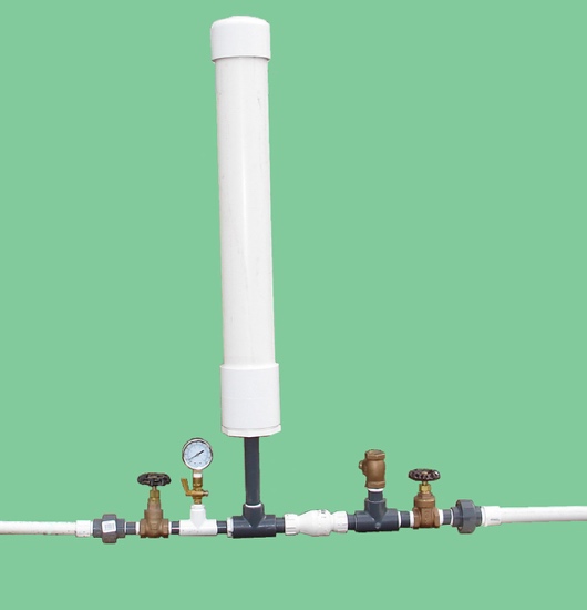
In this method of pump priming, water available at high head is allowed to flow through a nozzle. The nozzle is so designed that at the jet outside the nozzle the pressure is less than the atmospheric pressure so it is possible to suck water from the sump.
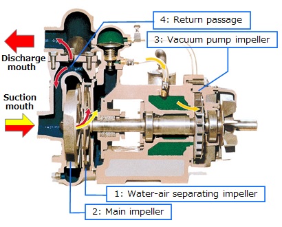
In this method of pump priming, air-water separation chamber is provided on the delivery side of pump and a bent suction pipe portion is provided at the inlet of the pump. Bent suction pipe portion always maintain some liquid in the pump. Air is separated and expelled through pump discharge or air vent and liquid, being heavier than air, falls back into separation chamber.
This design is made part of some self priming centrifugal pumps too. In self-priming centrifugal pumps with a separation chamber the fluid pumped and the entrained air bubbles are pumped into the separation chamber by the impeller action. The air escapes through the pump discharge nozzle whilst the fluid drops back down and is once more entrained by the impeller. The suction line is thus continuously evacuated. This design has two major drawbacks. Firstly reduced pump efficiency and secondly large dimensions due to incorporation of separation chamber.
In this method of pump priming, ejector is provided on the suction side of pump. Ejectors operate by creating a vacuum inside the suction line of the pump. The vacuum draws the liquids from sump up to the pump elevation. Ejectors require a Compressed Air Supply as an energy input.
In this method of pump priming, a foot valve (functioning as a NRV) is installed in the suction piping to insure that the liquid will not drain from the pump casing and suction piping once the pump stops operating. A foot valve is a form of check valve installed at the bottom, or foot, of a suction line. When the pump stops and the ports of the foot valve close, the liquid cannot drain back from pump suction if the valve seats tightly. Keep in mind that these foot valves have a nasty habit of leaking.
For prevention of a pump, where priming is required, operation without being primed various methods are being used. The basic of these methods are to trigger some form of alarm or auto shutdown of pump if the pump is not filled with liquid completely. One such scenario is discussed below.
In some pumps, a form of float switch in a chamber connected with the suction line is being used. If the level in the chamber is above the impeller eye of the pump, the float switch control allows the pump to operate. If the liquid falls below a safe level, the float switch acts through the control to stop the pump, to prevent its being started, to sound an alarm, or to light a warning lamp.
Self Priming Pumps are designed to have the ability to prime themselves automatically, when operating under a suction lift, to free themselves of entrained air or gases, and to continue normal pumping without external priming. They can be broken down into three basic types:
Liquid Primed Self Priming Pumps have their own in-built or separate liquid reservoir (known as “Priming Chamber”) that must be filled with liquid in order to “self prime” the pump. Without this initial liquid charge filled in priming chamber, a liquid primed self priming pump will not prime or pump. Liquid primed self priming pump generally operate in an air-liquid mixture by transforming this mixture into a fluid that can be pumped without help of any external auxiliary devices. Priming chamber allows liquid primed self priming pumps to recirculate liquid within the pump at will, ridding the pump of the air that prevents it from operating whenever necessary.
A Liquid Primed Self Priming Pump has two phases of operation: “Priming Mode” and “Pumping Mode”. During priming mode, the pump essentially acts as a liquid-ring pump. The rotating impeller generates a vacuum at the impeller’s ‘eye’ which draws air into the pump from the suction line. At the same time, it also creates a cylindrical ring of liquid on the inside of the pump casing. This effectively forms a gas-tight seal, stopping air returning from the discharge line to the suction line. Air bubbles are trapped in the liquid within the impeller’s vanes and transported to the discharge port. There, the air is expelled and the liquid returns under gravity to the reservoir (“Priming Chamber”) in the pump housing. Gradually, liquid rises up the suction line as the air is evacuated. This process continues until liquid replaces all the air in the suction piping and the pump. At this stage, the normal pumping mode commences, and liquid is discharged. If the attached discharge piping does not allow this separated air to escape out to the downstream discharge piping system, a bypass line may be required to evacuate it.
When the pump is shut off, the design of the priming chamber ensures that enough liquid is retained so that the pump can self prime on the next time it is operated. Liquid primed self priming pumps ability to operate in a mixture of air and liquid makes them far more versatile than their non self priming counterparts, which allows them to work in a broader range of environments and industries.
In Compressed Air Primed Self Priming Pumps, compressed air is blown through a jet into a tapered tube to create a vacuum, so air from the pump casing and suction line is drawn in with the compressed air and exhausted to the atmosphere. A non-return ball check valve seals out air from the discharge, allowing fluid to enter the pump body. Water then replaces the air which allows the pump to begin pumping. This pump type also avoids the potential build up of solids, since it has no priming chamber, so it can be used for sewage applications, plus it has dry running capability.
Vacuum Primed Self Priming Pumps typically has a vacuum pump and positive sealing float box installed at the pump discharge, close to the discharge valve. This allows it to pull a vacuum on the pump until it is full of water. Note that the maximum height that water can be lifted with a vacuum is 34 feet (at sea level), and that is with a perfect vacuum, and no liquid flowing. This pump type can have dry run capability, and is also capable of handling sewage.
Even a self priming pump has to be primed prior to its first operation. No matter the design, there is a priming chamber (integral or external) or some portion of the volute that will require filling prior to startup.
The discharge line must not be pressurized or blocked. The air in the suction side of the system being displaced by the liquid has to have somewhere to go, otherwise the pump will air bind.
The suction line must be air-tight. If air continues to be drawn into the pump, the pressure will never be reduced and fluid will not be drawn up the suction line.
Volume of the suction side piping to be minimized to reduce the priming time. With excessive priming times, there is a danger that the liquid charge will evaporate before the pump is primed.
If the liquid contains any solids, debris may collect in the re-circulation port, impeding the circulation of fluid and the generation of the liquid ring. For this a strainer may be required to keep solids from accumulating in the priming chamber and displacing the priming liquid.
When pumping liquid in cold conditions, the fluid in the priming chamber of the pump, usually water, will solidify if the ambient temperature drops below freezing for a sufficient period of time. When water freezes it expands and the casing will crack. Either drain the fluid out of the pump or supply a heat source when the ambient temperature is predicted to be below freezing.

www.powermotiontech.com is using a security service for protection against online attacks. An action has triggered the service and blocked your request.
Please try again in a few minutes. If the issue persist, please contact the site owner for further assistance. Reference ID IP Address Date and Time 8bf2006c85a66667641f5dd58dcb3d35 63.210.148.230 03/12/2023 05:15 AM UTC
Things like restrictions and blockages can impede the flow of fluid to your pump. which could contribute to poor fluid flow. Air leak in suction line. Air present in the pump at startup. Insufficient supply of oil in pump. Clogged or dirty fluid filters. Clogged inlet lines or hoses. Blocked reservoir breather vent. Low oil in the reservoir
Now that we’ve ensured that the directional control is not reversed, it’s time to check that the drive motor itself is turning in the right direction. Sometimes incorrect installation leads to mismatched pipe routings between control valves and motors, which can reverse the direction of flow. Check to see that the motor is turning the pump in the right direction and if not - look at your piping.
Check to ensure that your pump drive motor is turning over and is developing the required speed and torque. In some cases, misalignment can cause binding of the drive shaft, which can prevent the motor from turning. If this is the case, correct the misalignment and inspect the motor for damage. If required, overhaul or replace motor.
Check to ensure the pump to motor coupling is undamaged. A sheared pump coupling is an obvious cause of failure, however the location of some pumps within hydraulic systems makes this difficult to check so it may go overlooked
It is possible that the entire flow could be passing over the relief valve, preventing the pressure from developing. Check that the relief valve is adjusted properly for the pump specifications and the application.
Seized bearings, or pump shafts and other internal damage may prevent the pump from operating all together. If everything else checks out, uncouple the pump and motor and check to see that the pump shaft is able to turn. If not, overhaul or replace the pump.
If your pump is having problems developing sufficient power, following this checklist will help you to pinpoint the problem. In some cases you may find a simple solution is the answer. If your pump is exhibiting any other issues such as noise problems, heat problems or flow problems, you may need to do some more investigation to address the root cause of your pump problem. To help, we’ve created a downloadable troubleshooting guide containing more information about each of these issues. So that you can keep your system up and running and avoid unplanned downtime. Download it here.
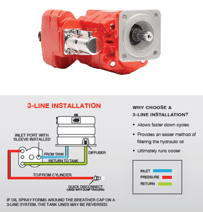
A gear pump is a type of positive displacement (PD) pump. It moves a fluid by repeatedly enclosing a fixed volume using interlocking cogs or gears, transferring it mechanically using a cyclic pumping action. It delivers a smooth pulse-free flow proportional to the rotational speed of its gears.
Gear pumps use the actions of rotating cogs or gears to transfer fluids. The rotating element develops a liquid seal with the pump casing and creates suction at the pump inlet. Fluid, drawn into the pump, is enclosed within the cavities of its rotating gears and transferred to the discharge. There are two basic designs of gear pump: external and internal(Figure 1).
An external gear pump consists of two identical, interlocking gears supported by separate shafts. Generally, one gear is driven by a motor and this drives the other gear (the idler). In some cases, both shafts may be driven by motors. The shafts are supported by bearings on each side of the casing.
As the gears come out of mesh on the inlet side of the pump, they create an expanded volume. Liquid flows into the cavities and is trapped by the gear teeth as the gears continue to rotate against the pump casing.
No fluid is transferred back through the centre, between the gears, because they are interlocked. Close tolerances between the gears and the casing allow the pump to develop suction at the inlet and prevent fluid from leaking back from the discharge side (although leakage is more likely with low viscosity liquids).
An internal gear pump operates on the same principle but the two interlocking gears are of different sizes with one rotating inside the other. The larger gear (the rotor) is an internal gear i.e. it has the teeth projecting on the inside. Within this is a smaller external gear (the idler –only the rotor is driven) mounted off-centre. This is designed to interlock with the rotor such that the gear teeth engage at one point. A pinion and bushing attached to the pump casing holds the idler in position. A fixed crescent-shaped partition or spacer fills the void created by the off-centre mounting position of the idler and acts as a seal between the inlet and outlet ports.
As the gears come out of mesh on the inlet side of the pump, they create an expanded volume. Liquid flows into the cavities and is trapped by the gear teeth as the gears continue to rotate against the pump casing and partition.
Gear pumps are compact and simple with a limited number of moving parts. They are unable to match the pressure generated by reciprocating pumps or the flow rates of centrifugal pumps but offer higher pressures and throughputs than vane or lobe pumps. Gear pumps are particularly suited for pumping oils and other high viscosity fluids.
Of the two designs, external gear pumps are capable of sustaining higher pressures (up to 3000 psi) and flow rates because of the more rigid shaft support and closer tolerances. Internal gear pumps have better suction capabilities and are suited to high viscosity fluids, although they have a useful operating range from 1cP to over 1,000,000cP. Since output is directly proportional to rotational speed, gear pumps are commonly used for metering and blending operations. Gear pumps can be engineered to handle aggressive liquids. While they are commonly made from cast iron or stainless steel, new alloys and composites allow the pumps to handle corrosive liquids such as sulphuric acid, sodium hypochlorite, ferric chloride and sodium hydroxide.
External gear pumps can also be used in hydraulic power applications, typically in vehicles, lifting machinery and mobile plant equipment. Driving a gear pump in reverse, using oil pumped from elsewhere in a system (normally by a tandem pump in the engine), creates a hydraulic motor. This is particularly useful to provide power in areas where electrical equipment is bulky, costly or inconvenient. Tractors, for example, rely on engine-driven external gear pumps to power their services.
Gear pumps are self-priming and can dry-lift although their priming characteristics improve if the gears are wetted. The gears need to be lubricated by the pumped fluid and should not be run dry for prolonged periods. Some gear pump designs can be run in either direction so the same pump can be used to load and unload a vessel, for example.
The close tolerances between the gears and casing mean that these types of pump are susceptible to wear particularly when used with abrasive fluids or feeds containing entrained solids. However, some designs of gear pumps, particularly internal variants, allow the handling of solids. External gear pumps have four bearings in the pumped medium, and tight tolerances, so are less suited to handling abrasive fluids. Internal gear pumps are more robust having only one bearing (sometimes two) running in the fluid. A gear pump should always have a strainer installed on the suction side to protect it from large, potentially damaging, solids.
Generally, if the pump is expected to handle abrasive solids it is advisable to select a pump with a higher capacity so it can be operated at lower speeds to reduce wear. However, it should be borne in mind that the volumetric efficiency of a gear pump is reduced at lower speeds and flow rates. A gear pump should not be operated too far from its recommended speed.
For high temperature applications, it is important to ensure that the operating temperature range is compatible with the pump specification. Thermal expansion of the casing and gears reduces clearances within a pump and this can also lead to increased wear, and in extreme cases, pump failure.
Despite the best precautions, gear pumps generally succumb to wear of the gears, casing and bearings over time. As clearances increase, there is a gradual reduction in efficiency and increase in flow slip: leakage of the pumped fluid from the discharge back to the suction side. Flow slip is proportional to the cube of the clearance between the cog teeth and casing so, in practice, wear has a small effect until a critical point is reached, from which performance degrades rapidly.
Gear pumps continue to pump against a back pressure and, if subjected to a downstream blockage will continue to pressurise the system until the pump, pipework or other equipment fails. Although most gear pumps are equipped with relief valves for this reason, it is always advisable to fit relief valves elsewhere in the system to protect downstream equipment.
Internal gear pumps, operating at low speed, are generally preferred for shear-sensitive liquids such as foodstuffs, paint and soaps. The higher speeds and lower clearances of external gear designs make them unsuitable for these applications. Internal gear pumps are also preferred when hygiene is important because of their mechanical simplicity and the fact that they are easy to strip down, clean and reassemble.
Gear pumps are commonly used for pumping high viscosity fluids such as oil, paints, resins or foodstuffs. They are preferred in any application where accurate dosing or high pressure output is required. The output of a gear pump is not greatly affected by pressure so they also tend to be preferred in any situation where the supply is irregular.
A gear pump moves a fluid by repeatedly enclosing a fixed volume within interlocking cogs or gears, transferring it mechanically to deliver a smooth pulse-free flow proportional to the rotational speed of its gears. There are two basic types: external and internal. An external gear pump consists of two identical, interlocking gears supported by separate shafts. An internal gear pump has two interlocking gears of different sizes with one rotating inside the other.
Gear pumps are commonly used for pumping high viscosity fluids such as oil, paints, resins or foodstuffs. They are also preferred in applications where accurate dosing or high pressure output is required. External gear pumps are capable of sustaining higher pressures (up to 7500 psi) whereas internal gear pumps have better suction capabilities and are more suited to high viscosity and shear-sensitive fluids.

?I get e-mails like this all the time. I never find time to read them. I decided to read Issue #30 and I couldn"t put it down. I"ll make time from now on.?
?I just love this newsletter. As a Hydraulics Instructor for Eaton, I make copies and distribute them to my students as I address various topics. Please keep "em coming.?

The long time shutoff of hydraulic machinery can easily damage the system components due to corrosion, lack of lubrication, contamination, and more. If the system is not maintained properly during the shutdown period, the consequences will be severe and it can even make the system fail. Also, while restarting the system, the operator or service technician is required to follow certain checks. In this article, we can discuss such checks that need to be performed on hydraulic pumps while restarting after a long shutoff.
Hydraulic pumps are the most important component of every hydraulic machinery with the role of pressurizing hydraulic oil. It is advised to perform basic maintenance on hydraulic systems in regular intervals to ensure long service life and smooth working. Also, the checks that need to be done prior to restarting are as follows.
Check if the pump spins freely: Keeping the pump in an idle position for a long time will make it difficult for the positive displacement and centrifugal pumps to spin freely. The procedure to spin the pump includes a lockout of the prime mover, removing the coupling guard and then turning the shaft. The rust, contamination, or any other mechanical issue will not allow the pump to spin freely or make noises while turning. In such conditions, don’t force the pump to move, instead inspect it by removing from the machinery. Only use a strap wrench to turn a positive displacement pump or other pumps that can’t be spinned manually. Using a torque wrench will cause more damage to the pump.
Check coupling & Mechanical Seal condition: The coupling used for pump installation will provide smooth and hassle-free functioning and rotation of the pump shaft. It is required to check the condition of coupling for evidence of wear. Any foreign particle present in the coupling will be proof of misalignment. In such conditions, check pump alignment before restarting.
The mechanical seal in the hydraulic system will prevent hydraulic fluid leakage. Also, checking these seals before restarting will help to detect system leakage and related injuries.
Check oil and lubrication levels: Hydraulic oil quality and quantity are significant for machine operation. Contaminants in hydraulic oil can damage the system components easily when the oil is not tested prior to restarting. To detect contaminants in the oil, a sample is taken for testing and oil properties are monitored. Also, all moving components in the system need to be lubricated properly for safe and error-free working.
Check Hoses, Clamps and Connections: Properly inspect hoses, clamps and connections to check if they are tightened properly. If not, this will create leakages and related issues. So, if loose connections are found, tighten it properly.
Check Valves and Filters: Filters will help to prevent contamination. Before restarting, check important filters like suction, pressure, and return filter, and replace the dirty/damaged filters. Also, check if the valves are arranged in the correct position for the startup.
Most experts agree that the majority of centrifugal pump problems occur on the suction side of the pump. Based solely on my experience, I would state the percentage is at least 80 percent, and in the case of self-priming pumps I am sure the percentage is higher.
Even a self-priming pump has to be primed prior to the first operation. No matter the manufacturer, there is a priming chamber (integral or external) or some portion of the volute that will require filling prior to startup. Please read the manual and/or contact the manufacturer for details. There are other methods to prime a pump, which include ancillary pumps, vacuum, vacuum ejectors and/or eductors. This article only addresses liquid self-priming centrifugal pumps.
Sometimes the pump will require manual re-priming after the initial prime. There can be several reasons for re-priming, one of the most common is evaporation of the fluid, and other reasons include leakage, pump movement and other maintenance related matters.
At sea level in a perfect world, you can theoretically lift 65-degree water 34 feet with a self-primer. I normally caution users to limit their suction lift to a maximum of 25 feet due to factors such as fluid temperature (think vapor pressure), specific gravity, friction, system leakage, pump inefficiencies and elevation above sea level.
Place the pump as close as possible to the suction source. Usually 25 to 30 feet is the maximum recommended distance. Prudent system design dictates that the suction pipe length be held to a minimum to promote long pump life. Every section of suction piping equates to a volume of air that must be removed when the pump starts. Best practices say to reduce priming time to a minimum.
Some system designers will add foot valves to mitigate the prime time and strainers to preclude the introduction of solids into the pump. A foot valve is in essence a check valve placed at the beginning (bottom) of the suction line. My experience is that foot valves add undesired friction and will leak or fail closed (or partially closed) at some point. I typically do not recommend foot valves for use on commercial and industrial self-primer applications. For similar reasons I do not recommend suction strainers. If the pump cannot handle solids and a strainer is utilized, monitor the differential pressure across the strainer. Most industrial self-priming pumps are of robust design and can handle passing solids, but check with the manufacturer. Note: A few applications may perform better with a foot valve.
I frequently need to point out to end users that the suction line on a self-primer pump in operation is at less than atmospheric pressure and so there will not be a leak of the liquid out of the suction line. There can, however, be a leak of air into the line. It is possible to have a suction line at 20 inches of Hg (vacuum) when the pump is operating. As a tip for field problem solving, I frequently use plastic wrap around the flanges or suspected areas to test for ingress leaks.
Simply as a general guideline, if your pump takes more than four minutes to prime than you should shut the pump down and look for and correct the cause of the problem.
The air in the suction side of the system being displaced by the liquid has to have somewhere to go, otherwise the pump will air bind. Centrifugal pumps are not compressors. Water is approximately 840 times denser than air. As an example if a pump was rated at a discharge pressure of 210 psig pumping water, the pump could theoretically compress air to approximately one quarter of a pound (0.25 psig) (210 psig divided by 840 is equal to 0.25). If the pump discharge valve and/or the discharge check valve are shut, the generated pressure of 0.25 psig will not be able to overcome the valves.
Within the confines of the article I will simply state that the air must be vented to an area of lower pressure for the pump to properly prime. There are many acceptable methods to accomplish the process, please contact your pump manufacturer or the author.
Most experienced pump users know that as a general rule you should always design the suction line to be one size larger than the pump suction. Self–priming pumps are an exception, and the suction piping should be the same size as the pump suction. The infraction of the rules is encouraged because of the added air volume that bigger suction lines require. More air means more priming time.
The suction pipe should rise continuously to the pump and not higher. In the field, I frequently see suction pipes with high points before the pump suction usually due to obstructions. These high points become a place for the air and other non-condensable gases to collect and will bind the pump suction line. Never install piping that is smaller than the pump suction in any pump.
I covered net positive suction head available (NPSHA) in last month"s article. I strongly recommend calculating the NPSHA for self-primers, as it is a great method to identify potential problem areas. For example, if the fluid is 160 degrees F, the vapor pressure of the fluid alone will likely preclude you from this application. For example, water at 160 F has a vapor pressure that equates to a negative 11 feet.
The sump you are drawing from will likely have operating levels that are constantly changing. At some value of minimum submergence it will be possible for the system to create a vortex and air bind the pump. I covered submergence in the last article, but simply defined, it is the minimum distance from the top of the fluid to the center of the suction line that will prevent a vortex from initiation. Even if you do not completely air bind, the pump performance can be affected.
This problem occurs more often in areas that have infrequent freezing weather, but can happen anywhere the temperature will drop below freezing for an hour or more. The fluid in the priming chamber of the pump, usually water, will solidify if the ambient temperature drops below freezing for a sufficient period of time. When water freezes it expands and the casing will crack. The casing will require replacement at a high cost. Either drain the fluid out of the pump or supply a heat source when the ambient temperature is predicted to be below freezing.
Unlike an ANSI pump, the impeller will stay in place on most self-primers for a period of time (unless it is an ANSI self-primer. Eventually the impeller may come loose and damage the pump. The backward-running impeller generally will create about 50 percent of the rated flow and, depending on the impeller specific speed (NS), will generate about 50 percent of the rated head. Reduced efficiency of the wrong rotation will likely prevent it from priming or operating correctly but in the simplest of suction lift cases.
Non-collapsible flex piping is commonly used on portable units. Normally the ID of flex pipe and adaptors are smaller than standard pipe. Think of the dimensions as tubing rather than pipe. Determination of the pipe friction for the NPSHa calculations will be incorrect if the reduced ID is neglected.
The pump performance must be de-rated for higher elevation changes (less absolute pressure less NPSHa). If the pump is engine driven in lieu of an electric motor, the resulting intermittent torque introduces limitations to the shaft design capabilities.

I was recently asked about a procedure for flushing hydraulic systems in order to change from one type of fluid to another. Among the ideas mentioned involved using brake cleaner, diesel fuel or some type of acid cleaning.
However, brake cleaner includes a number of chemicals such as acetone and tetrachloroethylene. These solvents are known to cause problems for nitrile, neoprene, millable polyurethane and silicone seals. Ethylene-propylene (EPDM) seals have a very poor petroleum oil and solvent resistance, and are not recommended for exposure to aromatic hydrocarbons or diesel oil.
Therefore, depending on the types of O-rings and seals in your hydraulic system, the solvents used in brake cleaner and diesel fuel can dry out or damage your system’s O-rings. There is also the issue of compatibility with the new type of fluid that has been chosen.
For these reasons, it"s important to understand flushing properly or to use an experienced oil flushing service provider who can help you get the job done right.
In his article for Machinery Lubrication titled “Cleaning and Flushing Basics for Hydraulic Systems and Similar Machines,” Tom Odden outlines the procedure for thoroughly cleaning a hydraulic system. This would be the only “one-size-fits-all” solution and an example of best practices. It involves mechanical and chemical cleaning of both the components and the system.
of lubrication professionals say mechanical cleaning is the flushing method used most frequently at their plant, according to a recent poll at machinerylubrication.com
Of course, not everyone is going to do a complete teardown along with a chemical and mechanical cleaning of each component and the system each time a fluid changeover is performed. So let’s examine what should be done at the bare minimum to clean a hydraulic system.
While the fluid is at operating temperature, completely drain the system, paying attention to the reservoir, all lines, cylinders, accumulators, filter housings or any area of fluid accumulation. Also, replace the filters.
Flush the system with a lower viscosity fluid that is similar to the fluid to be used. A Reynolds number between 2,000 and 4,000 should be selected to achieve enough turbulence to remove particles from the lines. Stroke valves frequently to ensure they are thoroughly flushed. The fluid should be filtered and the flushing should continue until reaching one level beyond the system’s target cleanliness levels. For example, if the target is ISO 15/13/11, continue to flush the system until ISO 14/12/10 is reached.
Fill the system to approximately 75 percent with the fluid to be used. Bleed/vent the pump. If the pump has a pressure relief or bypass, it should be wide open. Run the pump for 15 seconds, then stop and let it sit for 45 seconds. Repeat this procedure a few times to prime the pump.
Run the pump for a minute with the bypass or pressure relief open. Stop the pump and let it sit for a minute. Close the bypass and permit the pump to operate loaded for no more than five minutes. Allow the relief valve to lift to confirm that it is flushed as well. Do not operate the actuators at this time. Stop the pump and let the system sit for about five minutes.
Start the pump and operate the actuators one at a time, allowing fluid to return to the reservoir before moving to the next actuator. After operating the final actuator, shut down the system. Keep an eye on the fluid level in the reservoir. If the level drops below 25 percent, add fluid and fill to 50 percent.
Refill the reservoir to 75 percent and run the system in five-minute intervals. At each shutdown, bleed the air from the system. Pay close attention to the system sounds to determine if the pump is cavitating.
Run the system for 30 minutes to bring it to normal operating temperature. Shut down the system and replace the filters. Inspect the reservoir for obvious signs of cross-contamination. If any indication of cross-contamination is present, drain and flush the system again.
There are a lot of different ways to flush out a machine. You want to match the flushing method to the flushing condition. Following are common tactics for accomplishing this:
High Turbulence, High Fluid Velocity, Low Oil Viscosity — Flushing is enhanced by high turbulence flushing conditions by lower flush oil viscosity and increasing oil flow rates. This usually requires specialized equipment to achieve proper turbulent flow. Talk to a service provideryou trust who offers high-velocity oil flushing services.
High Flush Oil Temperature — This reduces viscosity, increases turbulence and increases oil solvency. Temperatures in the range of 175 to 195 degrees F are generally targeted.
Cycling Flush Oil Temperature— Using heat exchangers and coolers to change temperature during flushing across a 100 degree F range helps dislodge crusty surface deposits.
Wand Flush Tool — Used for wet sumps, gearboxes and reservoirs with access hatches and clean-out ports. A wand on the end of a flushing hose is used to direct high-velocity oil flow to loosen deposits or for picking up bottom sediment.
Charged Particle (Electrostatic) Separators — Some suppliers have demonstrated success at removing varnish from machine surfaces and stripping out submicron soft contaminants that can contribute to varnish and sludge.
Solvent/Detergent Flush Fluid — Various solvents and detergents have been used with different degrees of success, including mineral spirits, diesel fuel, motor oils and detergent/dispersant packages.
Chemical Cleaning — These are chemically active compounds, typically caustics and acids, used to aid in the removal of organic sludge and oxide deposits.
Mechanical Cleaning — This involves the use of scrapers, brushes and abrasives, typically used with solvents and other chemicals, to remove hard adherent surface deposits.
Some adherent machine deposits require tactics that are more aggressive than a high-velocity flush, so you must match the flushing tactic and strategy to the problem you are trying to resolve with the flush. Once you understand the problem within the machine that needs to be cleaned, you can then select the appropriate flushing tactic to remedy it. This issue was described in Jim Fitch’s three-part series on flushing for Machinery Lubrication, which can be read at www.machinerylubrication.com/Read/609/oil-flush, www.machinerylubrication.com/Read/634/oil-flushing-tactics and www.machinerylubrication.com/Read/657/flushing-oil.
At this point, it should be obvious that a fluid changeout is not just a drain-and-fill operation. Care must be taken to confirm that the system is as clean as possible prior to introducing the new fluid. Most changeover procedures suggest that some of the old fluid will need to be either drained off the bottom or skimmed off the top of the reservoir after a period of time.
Just because the changeover has been completed does not mean that you are “out of the woods.” Your system will need to be closely monitored for a while to make certain that the flushing was thorough. Taking the time to verify that the system is fully flushed and purged of the old fluid prior to introducing the new fluid will go a long way toward ensuring a healthier hydraulic system.
A hydraulic pump converts mechanical energy into fluid power. It"s used in hydraulic systems to perform work, such as lifting heavy loads in excavators or jacks to being used in hydraulic splitters. This article focuses on how hydraulic pumps operate, different types of hydraulic pumps, and their applications.
A hydraulic pump operates on positive displacement, where a confined fluid is subjected to pressure using a reciprocating or rotary action. The pump"s driving force is supplied by a prime mover, such as an electric motor, internal combustion engine, human labor (Figure 1), or compressed air (Figure 2), which drives the impeller, gear (Figure 3), or vane to create a flow of fluid within the pump"s housing.
A hydraulic pump’s mechanical action creates a vacuum at the pump’s inlet, which allows atmospheric pressure to force fluid into the pump. The drawn in fluid creates a vacuum at the inlet chamber, which allows the fluid to then be forced towards the outlet at a high pressure.
Vane pump:Vanes are pushed outwards by centrifugal force and pushed back into the rotor as they move past the pump inlet and outlet, generating fluid flow and pressure.
Piston pump:A piston is moved back and forth within a cylinder, creating chambers of varying size that draw in and compress fluid, generating fluid flow and pressure.
A hydraulic pump"s performance is determined by the size and shape of the pump"s internal chambers, the speed at which the pump operates, and the power supplied to the pump. Hydraulic pumps use an incompressible fluid, usually petroleum oil or a food-safe alternative, as the working fluid. The fluid must have lubrication properties and be able to operate at high temperatures. The type of fluid used may depend on safety requirements, such as fire resistance or food preparation.
Air hydraulic pump:These pumps have a compact design and do not require an external power source. However, a reliable source of compressed air is necessary and is limited by the supply pressure of compressed air.
Electric hydraulic pump:They have a reliable and efficient power source and can be easily integrated into existing systems. However, these pumps require a constant power source, may be affected by power outages, and require additional electrical safety measures. Also, they have a higher upfront cost than other pump types.
Gas-powered hydraulic pump:Gas-powered pumps are portable hydraulic pumps which are easy to use in outdoor and remote environments. However, they are limited by fuel supply, have higher emissions compared to other hydraulic pumps, and the fuel systems require regular maintenance.
Manual hydraulic pump:They are easy to transport and do not require a power source. However, they are limited by the operator’s physical ability, have a lower flow rate than other hydraulic pump types, and may require extra time to complete tasks.
Hydraulic hand pump:Hydraulic hand pumps are suitable for small-scale, and low-pressure applications and typically cost less than hydraulic foot pumps.
Hydraulic foot pump:Hydraulic foot pumps are suitable for heavy-duty and high-pressure applications and require less effort than hydraulic hand pumps.
Hydraulic pumps can be single-acting or double-acting. Single-acting pumps have a single port that hydraulic fluid enters to extend the pump’s cylinder. Double-acting pumps have two ports, one for extending the cylinder and one for retracting the cylinder.
Single-acting:With single-acting hydraulic pumps, the cylinder extends when hydraulic fluid enters it. The cylinder will retract with a spring, with gravity, or from the load.
Double-acting:With double-acting hydraulic pumps, the cylinder retracts when hydraulic fluid enters the top port. The cylinder goes back to its starting position.
Single-acting:Single-acting hydraulic pumps are suitable for simple applications that only need linear movement in one direction. For example, such as lifting an object or pressing a load.
Double-acting:Double-acting hydraulic pumps are for applications that need precise linear movement in two directions, such as elevators and forklifts.
Pressure:Hydraulic gear pumps and hydraulic vane pumps are suitable for low-pressure applications, and hydraulic piston pumps are suitable for high-pressure applications.
Cost:Gear pumps are the least expensive to purchase and maintain, whereas piston pumps are the most expensive. Vane pumps land somewhere between the other two in cost.
Efficiency:Gear pumps are the least efficient. They typically have 80% efficiency, meaning 10 mechanical horsepower turns into 8 hydraulic horsepower. Vane pumps are more efficient than gear pumps, and piston pumps are the most efficient with up to 95% efficiency.
Automotive industry:In the automotive industry, hydraulic pumps are combined with jacks and engine hoists for lifting vehicles, platforms, heavy loads, and pulling engines.
Process and manufacturing:Heavy-duty hydraulic pumps are used for driving and tapping applications, turning heavy valves, tightening, and expanding applications.
Despite the different pump mechanism types in hydraulic pumps, they are categorized based on size (pressure output) and driving force (manual, air, electric, and fuel-powered). There are several parameters to consider while selecting the right hydraulic pump for an application. The most important parameters are described below:
Source of driving force: Is it to be manually operated (by hand or foot), air from a compressor, electrical power, or a fuel engine as a prime mover? Other factors that may affect the driving force type are whether it will be remotely operated or not, speed of operation, and load requirement.
Speed of operation: If it is a manual hydraulic pump, should it be a single-speed or double-speed? How much volume of fluid per handle stroke? When using a powered hydraulic pump, how much volume per minute? Air, gas, and electric-powered hydraulic pumps are useful for high-volume flows.
Portability: Manual hand hydraulic pumps are usually portable but with lower output, while fuel power has high-output pressure but stationary for remote operations in places without electricity. Electric hydraulic pumps can be both mobile and stationary, as well as air hydraulic pumps. Air hydraulic pumps require compressed air at the operation site.
Operating temperature: The application operating temperature can affect the size of the oil reservoir needed, the type of fluid, and the materials used for the pump components. The oil is the operating fluid but also serves as a cooling liquid in heavy-duty hydraulic pumps.
Operating noise: Consider if the environment has a noise requirement. A hydraulic pump with a fuel engine will generate a higher noise than an electric hydraulic pump of the same size.
Spark-free: Should the hydraulic pump be spark-free due to a possible explosive environment? Remember, most operating fluids are derivatives of petroleum oil, but there are spark-free options.
A hydraulic pump transforms mechanical energy into fluid energy. A relatively low amount of input power can turn into a large amount of output power for lifting heavy loads.
A hydraulic pump works by using mechanical energy to pressurize fluid in a closed system. This pressurized fluid is then used to drive machinery such as excavators, presses, and lifts.
A hydraulic ram pump leverages the energy of falling water to move water to a higher height without the usage of external power. It is made up of a valve, a pressure chamber, and inlet and exit pipes.
A water pump moves water from one area to another, whereas a hydraulic pump"s purpose is to overcome a pressure that is dependent on a load, like a heavy car.

SKD self-priming rotodynamic pumps with side channel and centrifugal impeller before the first stage serve to pump liquids within the corrosion resistance limits of materials used for their construction. Liquids can contain trace amounts of solid particles up to 0.5 mm in size. SKD is a self-priming pump. Pump priming is necessary but there is no need to prime its suction pipeline with liquid.
SKD pumps can pump liquid with a minimum excess pressure over boiling point. Small NPSHr net positive suction head in pumping system and very good priming ability are of particular advantage.
At SKD pumps suction side there is an axial inlet of increased diameter, outlet opening at the discharge side is directed vertically upwards. Before the first stage at the suction side a centrifugal impeller and stator are applied. Pump stages are typical circulation pump stages with side channels and open impellers. Encased ball bearings and an appropriate shaft seal are located at the pump discharge side. Depending on pump purpose and constructional execution a front seal is used, among others things, to ensure total tightness.
The front seal can be lubricated and flushed with pumped or outside liquid. In LPG-execution pumps a special sealing LOCTITE-573 mass is applied, in other executions 0.11 mm thick gaskets are used between stages. LPG pumps are subject to a special test for tightness and mechanical strength. The SKD pump is additionally equipped with a diffuser installed on its suction housing, and with a circulation pipe through which the slide bearing placed in pump stator is lubricated by liquid contained in the pump when it pumps air from suction pipeline.
Liquid compounds like propane-butane and other mixtures are subject to specific laws of physics. Propane-butane liquefied gas is a mixture of upper saturated hydrocarbons characterized with high vapour pressure dependence on ambient temperature. In normal physical conditions (1013 hPa, 20oC) they are heavier than air (gas density is higher than air density) and when their outflow is uncontrolled, they trail close to the ground surface filling all hollows in. In its volatile phase the gas is highly inflammable and when mixed with air creates a very dangerous explosive mixture. In its liquid phase it is lighter than water and, when evaporating, floats on the surface. Passing from liquid to the volatile phase in a free space begins at -30oC (50/50 propane/butane mixture). To keep the propane-butane mix in liquid state during the whole distribution process and especially at the pump first stage impeller inflow, liquid pressure must be subjected to any excess pressure Ap in relation to its value determined from the liquid evaporation curve.
When the required Hzsvalue calculated for the complex (LPG station) in the technical project is not met, it will lead to pump destruction. Destruction of the front mechanical seals on the pump shaft, pump slide bearing and the whole hydraulic system (impellers and members) is likely. A properly designed pumping system must fulfil the conditions:
When performing the installation, the following technical requirements should be observed:strive to limit flow resistance in the suction pipe to the minimum,
Inflow height Hzs [m] specified on the basis of geometrical formula must be unconditionally kept. The ball valve at the pump discharge side must be half-open during pump switch-off. When the ball valve is fully open a danger of total gas evaporation exists (pump will operate off its catalogue operating range). Both ball bearings: in the pressure equalization conduit at the suction side to the tank and at the suction side must be fully open. One should be absolutely sure that the pump is filled with liquid gas during the pump start up.
suction pipeline minimum diameter should be at least equal to pump connector diameter (dr>ds) on the whole pipeline length (from tank outlet to pump connection),

When a hydraulic system fails, finding the source of the problem can be a challenge. Though hydraulic systems primarily consist of a sump, motor, pump, valves, actuators and hydraulic fluid, any of these parts could be the source of failure. That"s not to mention the additional potential for failure through human error and faulty maintenance practices. If your system fails, you need to know why it fails, how to find the failure and how to keep it running smoothly in the future, all while keeping personnel safe.
It"s often easy to tell when a hydraulic system fails — symptoms can include high temperatures, low pressure readings and slow or erratic operation are glaring problems. But what are the most common causes of hydraulic systems failures? We can trace most hydraulic issues back to a few common causes, listed below.
Air and water contamination are the leading causes of hydraulic failure, accounting for 80 to 90% of hydraulic failures. Faulty pumps, system breaches or temperature issues often cause both types of contamination.
Air contamination is the entrance of air into a hydraulic system and consists of two types — aeration and cavitation. Both can cause severe damage to the hydraulic system over time by wearing down the pump and surrounding components, contaminating hydraulic fluids and even overheating the system. Although we are not pump manufacturers, we know it is essential to be aware of these types of contamination and how to identify their symptoms.
Cavitation:Hydraulic oil consists of about 9% dissolved air, which the pump can pull out and implode, causing pump problems and damage to the pump and to other components in a hydraulic system over time. You can identify this problem if your hydraulic pump is making a whining noise.
Aeration:Aeration occurs when air enters the pump cavity from an outside source. Usually, loose connections or leaks in the system cause this issue. Aeration also creates a sound when the pump is running, which sounds like knocking.
Water contamination is also a common problem in hydraulic systems, often caused by system leaks or condensation due to temperature changes. Water can degrade hydraulic components over time through oxidation and freeze damage. A milky appearance in hydraulic fluid can help you identify water contamination.
Fluid oxidization: Extreme heat can cause hydraulic fluid to oxidize and thicken. This fluid thickening can cause buildups in the system that restrict flow, but can also further reduce the ability of the system to dissipate heat.
Fluid thickening:Low temperatures increase the viscosity of hydraulic oil, making it harder for the oil to reach the pump. Putting systems under load before the oil reaches 70 degrees or more can damage the system through cavitation.
Fluid levels and quality can affect hydraulic system performance. Low fluid levels and inappropriate filtration can result in air contamination, while fluid contamination can cause temperature problems. Leaks can further exacerbate both issues.
Using the correct type of fluid is also essential, as certain hydraulic oils are compatible with specific applications. There are even oil options that offer higher resistance to temperature-related problems. Some oils even offer anti-wear and anti-foam additives to help prevent against wear and air contamination, respectively.
Human error is the base cause of many hydraulic system problems. Some of the most common errors that may result in your hydraulic pump not building pressure include the following.
Faulty installations: Improper installation of any component in a hydraulic system can result in severe errors. For example, the pump shaft may be rotating in the wrong direction, negatively affecting pressure buildup, or pipes may be incorrectly fitted, resulting in leaks.
Incompatible parts: An inexperienced installer may put mismatched components together, resulting in functional failures. For example, a pump may have a motor that runs beyond its maximum drive speed.
Improper maintenance or usage:Using systems outside their operational capabilities or failing to perform regular maintenance are some of the most common causes of hydraulic system damage, but are easy to rectify through updated maintenance policies and training.
The sources of system failures can be tricky to identify, but some hydraulic troubleshooting steps can help narrow down the options. So how do you troubleshoot a hydraulic system? Here are some of the fundamentals.
Check the pump: Take the pump assembly apart and assess all parts to ensure that they are functional and installed correctly. The most common problem areas include the pump shaft, coupling and filter.
Check the fluids:Check the level, color and viscosity of the hydraulic oil to ensure it meets specifications and has not become contaminated. Low hydraulic fluid symptoms include pressure or power loss. When in doubt, drain and replace the fluids.
Check the seals: Look for evidence of any fluid leakage around your hydraulic system"s seals, especially the shaft seal. Leakage can indicate worn-out or blown seals that can cause malfunctions with pumps, motors and control valves.
Check the filters: Ensure filters are clear of plugs and blockages. Common clogged hydraulic filter symptoms include sluggish operation and noisy operation.
Check valves and lines: Observe all lines for potential leaks, and tighten every connection point. Also, check the relief valve for any signs of damage.
Run the system: When you have completed all these essential checks, turn on the system and monitor it for pressure and temperature fluctuations, as well as abnormal sounds. If all seems well, check your pressure sensor for potential failure.
Hydraulic system issues are inevitable at some point. However, simple steps can help you avoid these issues and increase the longevity of your hydraulic system. On top of effective troubleshooting, you can prevent hydraulic system failure by taking the following steps.
Follow specifications: We can trace the most common hydraulic system issues back to fundamental system problems like incompatible or improperly installed parts. For this reason, it"s essential to always double-check specifications to ensure your purchased parts can work together seamlessly.
Consult with professionals: When purchasing new equipment, consult with industry peers and professionals to discover what they recommend. While manufacturers can tell you how a product should work, industry professionals can provide concrete examples of how well the equipment works for their industry.
Perform maintenance: It is essential to focus your operations on equipment longevity. Review your daily, m


 8613371530291