
priming a hydraulic pump made in china
This website is using a security service to protect itself from online attacks. The action you just performed triggered the security solution. There are several actions that could trigger this block including submitting a certain word or phrase, a SQL command or malformed data.

This website is using a security service to protect itself from online attacks. The action you just performed triggered the security solution. There are several actions that could trigger this block including submitting a certain word or phrase, a SQL command or malformed data.

The owner of this website (china.tradeford.com) has banned the autonomous system number (ASN) your IP address is in (20473) from accessing this website.

3407 hydraulic hand pump made in china products are offered for sale by suppliers on Alibaba.comAbout 1% % of these are pumps, 1%% are hydraulic pumps, and 1%% are hydraulics pumps.
A wide variety of hydraulic hand pump made in china options are available to you, such as new, used.You can also choose from piston pump, gear pump and vane pump hydraulic hand pump made in china,as well as from 1 year, 6 months, and 1.5 years hydraulic hand pump made in china,and whether hydraulic hand pump made in china is hydraulic power units, or hydraulic accumulators.

Mechanical pumps serve in a wide range of applications such as pumping water from wells, aquarium filtering, pond filtering and aeration, in the car industry for water-cooling and fuel injection, in the energy industry for pumping oil and natural gas or for operating cooling towers and other components of heating, ventilation and air conditioning systems. In the medical industry, pumps are used for biochemical processes in developing and manufacturing medicine, and as artificial replacements for body parts, in particular the artificial heart and penile prosthesis.
When a pump contains two or more pump mechanisms with fluid being directed to flow through them in series, it is called a multi-stage pump. Terms such as two-stage or double-stage may be used to specifically describe the number of stages. A pump that does not fit this description is simply a single-stage pump in contrast.
In biology, many different types of chemical and biomechanical pumps have evolved; biomimicry is sometimes used in developing new types of mechanical pumps.
Pumps can be classified by their method of displacement into positive-displacement pumps, impulse pumps, velocity pumps, gravity pumps, steam pumps and valveless pumps. There are three basic types of pumps: positive-displacement, centrifugal and axial-flow pumps. In centrifugal pumps the direction of flow of the fluid changes by ninety degrees as it flows over an impeller, while in axial flow pumps the direction of flow is unchanged.
Some positive-displacement pumps use an expanding cavity on the suction side and a decreasing cavity on the discharge side. Liquid flows into the pump as the cavity on the suction side expands and the liquid flows out of the discharge as the cavity collapses. The volume is constant through each cycle of operation.
Positive-displacement pumps, unlike centrifugal, can theoretically produce the same flow at a given speed (rpm) no matter what the discharge pressure. Thus, positive-displacement pumps are constant flow machines. However, a slight increase in internal leakage as the pressure increases prevents a truly constant flow rate.
A positive-displacement pump must not operate against a closed valve on the discharge side of the pump, because it has no shutoff head like centrifugal pumps. A positive-displacement pump operating against a closed discharge valve continues to produce flow and the pressure in the discharge line increases until the line bursts, the pump is severely damaged, or both.
A relief or safety valve on the discharge side of the positive-displacement pump is therefore necessary. The relief valve can be internal or external. The pump manufacturer normally has the option to supply internal relief or safety valves. The internal valve is usually used only as a safety precaution. An external relief valve in the discharge line, with a return line back to the suction line or supply tank provides increased safety.
Rotary-type positive displacement: internal or external gear pump, screw pump, lobe pump, shuttle block, flexible vane or sliding vane, circumferential piston, flexible impeller, helical twisted roots (e.g. the Wendelkolben pump) or liquid-ring pumps
Drawbacks: The nature of the pump requires very close clearances between the rotating pump and the outer edge, making it rotate at a slow, steady speed. If rotary pumps are operated at high speeds, the fluids cause erosion, which eventually causes enlarged clearances that liquid can pass through, which reduces efficiency.
Hollow disk pumps (also known as eccentric disc pumps or Hollow rotary disc pumps), similar to scroll compressors, these have a cylindrical rotor encased in a circular housing. As the rotor orbits and rotates to some degree, it traps fluid between the rotor and the casing, drawing the fluid through the pump. It is used for highly viscous fluids like petroleum-derived products, and it can also support high pressures of up to 290 psi.
Vibratory pumps or vibration pumps are similar to linear compressors, having the same operating principle. They work by using a spring-loaded piston with an electromagnet connected to AC current through a diode. The spring-loaded piston is the only moving part, and it is placed in the center of the electromagnet. During the positive cycle of the AC current, the diode allows energy to pass through the electromagnet, generating a magnetic field that moves the piston backwards, compressing the spring, and generating suction. During the negative cycle of the AC current, the diode blocks current flow to the electromagnet, letting the spring uncompress, moving the piston forward, and pumping the fluid and generating pressure, like a reciprocating pump. Due to its low cost, it is widely used in inexpensive espresso machines. However, vibratory pumps cannot be operated for more than one minute, as they generate large amounts of heat. Linear compressors do not have this problem, as they can be cooled by the working fluid (which is often a refrigerant).
Reciprocating pumps move the fluid using one or more oscillating pistons, plungers, or membranes (diaphragms), while valves restrict fluid motion to the desired direction. In order for suction to take place, the pump must first pull the plunger in an outward motion to decrease pressure in the chamber. Once the plunger pushes back, it will increase the chamber pressure and the inward pressure of the plunger will then open the discharge valve and release the fluid into the delivery pipe at constant flow rate and increased pressure.
Pumps in this category range from simplex, with one cylinder, to in some cases quad (four) cylinders, or more. Many reciprocating-type pumps are duplex (two) or triplex (three) cylinder. They can be either single-acting with suction during one direction of piston motion and discharge on the other, or double-acting with suction and discharge in both directions. The pumps can be powered manually, by air or steam, or by a belt driven by an engine. This type of pump was used extensively in the 19th century—in the early days of steam propulsion—as boiler feed water pumps. Now reciprocating pumps typically pump highly viscous fluids like concrete and heavy oils, and serve in special applications that demand low flow rates against high resistance. Reciprocating hand pumps were widely used to pump water from wells. Common bicycle pumps and foot pumps for inflation use reciprocating action.
These positive-displacement pumps have an expanding cavity on the suction side and a decreasing cavity on the discharge side. Liquid flows into the pumps as the cavity on the suction side expands and the liquid flows out of the discharge as the cavity collapses. The volume is constant given each cycle of operation and the pump"s volumetric efficiency can be achieved through routine maintenance and inspection of its valves.
This is the simplest form of rotary positive-displacement pumps. It consists of two meshed gears that rotate in a closely fitted casing. The tooth spaces trap fluid and force it around the outer periphery. The fluid does not travel back on the meshed part, because the teeth mesh closely in the center. Gear pumps see wide use in car engine oil pumps and in various hydraulic power packs.
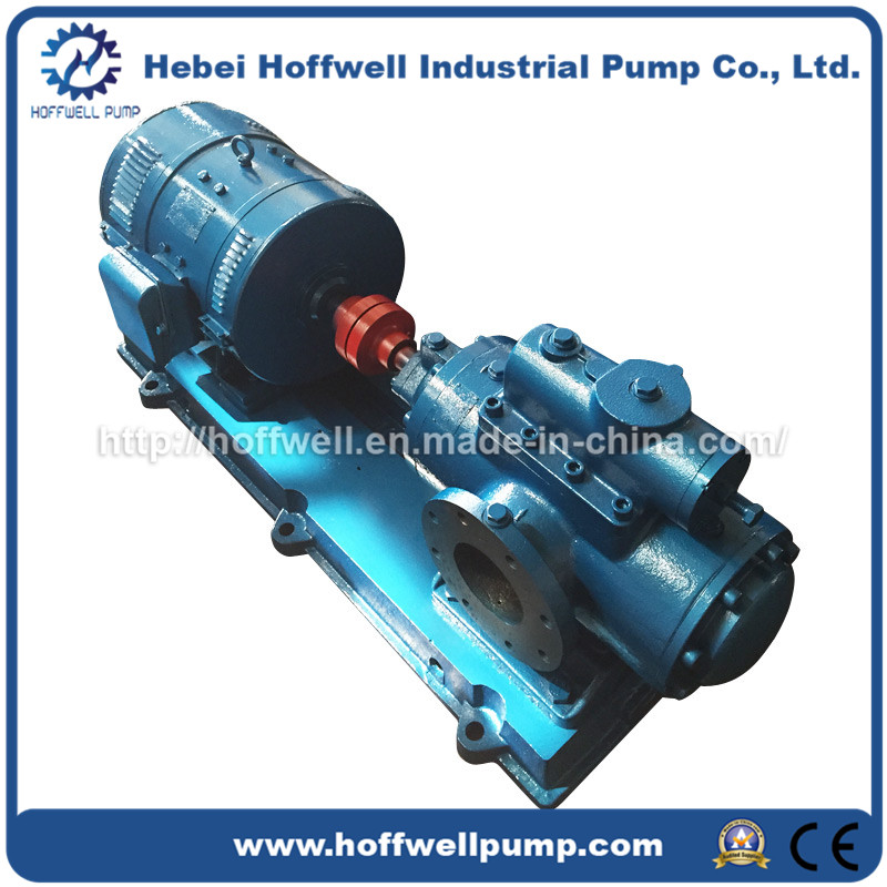
A screw pump is a more complicated type of rotary pump that uses two or three screws with opposing thread — e.g., one screw turns clockwise and the other counterclockwise. The screws are mounted on parallel shafts that have gears that mesh so the shafts turn together and everything stays in place. The screws turn on the shafts and drive fluid through the pump. As with other forms of rotary pumps, the clearance between moving parts and the pump"s casing is minimal.
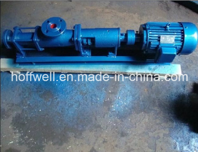
Widely used for pumping difficult materials, such as sewage sludge contaminated with large particles, a progressing cavity pump consists of a helical rotor, about ten times as long as its width. This can be visualized as a central core of diameter x with, typically, a curved spiral wound around of thickness half x, though in reality it is manufactured in a single casting. This shaft fits inside a heavy-duty rubber sleeve, of wall thickness also typically x. As the shaft rotates, the rotor gradually forces fluid up the rubber sleeve. Such pumps can develop very high pressure at low volumes.
Named after the Roots brothers who invented it, this lobe pump displaces the fluid trapped between two long helical rotors, each fitted into the other when perpendicular at 90°, rotating inside a triangular shaped sealing line configuration, both at the point of suction and at the point of discharge. This design produces a continuous flow with equal volume and no vortex. It can work at low pulsation rates, and offers gentle performance that some applications require.
A peristaltic pump is a type of positive-displacement pump. It contains fluid within a flexible tube fitted inside a circular pump casing (though linear peristaltic pumps have been made). A number of rollers, shoes, or wipers attached to a rotor compresses the flexible tube. As the rotor turns, the part of the tube under compression closes (or occludes), forcing the fluid through the tube. Additionally, when the tube opens to its natural state after the passing of the cam it draws (restitution) fluid into the pump. This process is called peristalsis and is used in many biological systems such as the gastrointestinal tract.
These consist of a cylinder with a reciprocating plunger. The suction and discharge valves are mounted in the head of the cylinder. In the suction stroke, the plunger retracts and the suction valves open causing suction of fluid into the cylinder. In the forward stroke, the plunger pushes the liquid out of the discharge valve.
Efficiency and common problems: With only one cylinder in plunger pumps, the fluid flow varies between maximum flow when the plunger moves through the middle positions, and zero flow when the plunger is at the end positions. A lot of energy is wasted when the fluid is accelerated in the piping system. Vibration and
Triplex plunger pumps use three plungers, which reduces the pulsation of single reciprocating plunger pumps. Adding a pulsation dampener on the pump outlet can further smooth the pump ripple, or ripple graph of a pump transducer. The dynamic relationship of the high-pressure fluid and plunger generally requires high-quality plunger seals. Plunger pumps with a larger number of plungers have the benefit of increased flow, or smoother flow without a pulsation damper. The increase in moving parts and crankshaft load is one drawback.
Car washes often use these triplex-style plunger pumps (perhaps without pulsation dampers). In 1968, William Bruggeman reduced the size of the triplex pump and increased the lifespan so that car washes could use equipment with smaller footprints. Durable high-pressure seals, low-pressure seals and oil seals, hardened crankshafts, hardened connecting rods, thick ceramic plungers and heavier duty ball and roller bearings improve reliability in triplex pumps. Triplex pumps now are in a myriad of markets across the world.
Triplex pumps with shorter lifetimes are commonplace to the home user. A person who uses a home pressure washer for 10 hours a year may be satisfied with a pump that lasts 100 hours between rebuilds. Industrial-grade or continuous duty triplex pumps on the other end of the quality spectrum may run for as much as 2,080 hours a year.
The oil and gas drilling industry uses massive semi trailer-transported triplex pumps called mud pumps to pump drilling mud, which cools the drill bit and carries the cuttings back to the surface.
One modern application of positive-displacement pumps is compressed-air-powered double-diaphragm pumps. Run on compressed air, these pumps are intrinsically safe by design, although all manufacturers offer ATEX certified models to comply with industry regulation. These pumps are relatively inexpensive and can perform a wide variety of duties, from pumping water out of bunds to pumping hydrochloric acid from secure storage (dependent on how the pump is manufactured – elastomers / body construction). These double-diaphragm pumps can handle viscous fluids and abrasive materials with a gentle pumping process ideal for transporting shear-sensitive media.
Devised in China as chain pumps over 1000 years ago, these pumps can be made from very simple materials: A rope, a wheel and a pipe are sufficient to make a simple rope pump. Rope pump efficiency has been studied by grassroots organizations and the techniques for making and running them have been continuously improved.
Impulse pumps use pressure created by gas (usually air). In some impulse pumps the gas trapped in the liquid (usually water), is released and accumulated somewhere in the pump, creating a pressure that can push part of the liquid upwards.
Instead of a gas accumulation and releasing cycle, the pressure can be created by burning of hydrocarbons. Such combustion driven pumps directly transmit the impulse from a combustion event through the actuation membrane to the pump fluid. In order to allow this direct transmission, the pump needs to be almost entirely made of an elastomer (e.g. silicone rubber). Hence, the combustion causes the membrane to expand and thereby pumps the fluid out of the adjacent pumping chamber. The first combustion-driven soft pump was developed by ETH Zurich.
It takes in water at relatively low pressure and high flow-rate and outputs water at a higher hydraulic-head and lower flow-rate. The device uses the water hammer effect to develop pressure that lifts a portion of the input water that powers the pump to a point higher than where the water started.
The hydraulic ram is sometimes used in remote areas, where there is both a source of low-head hydropower, and a need for pumping water to a destination higher in elevation than the source. In this situation, the ram is often useful, since it requires no outside source of power other than the kinetic energy of flowing water.
Rotodynamic pumps (or dynamic pumps) are a type of velocity pump in which kinetic energy is added to the fluid by increasing the flow velocity. This increase in energy is converted to a gain in potential energy (pressure) when the velocity is reduced prior to or as the flow exits the pump into the discharge pipe. This conversion of kinetic energy to pressure is explained by the
A practical difference between dynamic and positive-displacement pumps is how they operate under closed valve conditions. Positive-displacement pumps physically displace fluid, so closing a valve downstream of a positive-displacement pump produces a continual pressure build up that can cause mechanical failure of pipeline or pump. Dynamic pumps differ in that they can be safely operated under closed valve conditions (for short periods of time).
Such a pump is also referred to as a centrifugal pump. The fluid enters along the axis or center, is accelerated by the impeller and exits at right angles to the shaft (radially); an example is the centrifugal fan, which is commonly used to implement a vacuum cleaner. Another type of radial-flow pump is a vortex pump. The liquid in them moves in tangential direction around the working wheel. The conversion from the mechanical energy of motor into the potential energy of flow comes by means of multiple whirls, which are excited by the impeller in the working channel of the pump. Generally, a radial-flow pump operates at higher pressures and lower flow rates than an axial- or a mixed-flow pump.
These are also referred to as All fluid pumps. The fluid is pushed outward or inward to move fluid axially. They operate at much lower pressures and higher flow rates than radial-flow (centrifugal) pumps. Axial-flow pumps cannot be run up to speed without special precaution. If at a low flow rate, the total head rise and high torque associated with this pipe would mean that the starting torque would have to become a function of acceleration for the whole mass of liquid in the pipe system. If there is a large amount of fluid in the system, accelerate the pump slowly.
Mixed-flow pumps function as a compromise between radial and axial-flow pumps. The fluid experiences both radial acceleration and lift and exits the impeller somewhere between 0 and 90 degrees from the axial direction. As a consequence mixed-flow pumps operate at higher pressures than axial-flow pumps while delivering higher discharges than radial-flow pumps. The exit angle of the flow dictates the pressure head-discharge characteristic in relation to radial and mixed-flow.
Regenerative turbine pump rotor and housing, 1⁄3 horsepower (0.25 kW). 85 millimetres (3.3 in) diameter impeller rotates counter-clockwise. Left: inlet, right: outlet. .4 millimetres (0.016 in) thick vanes on 4 millimetres (0.16 in) centers
Also known as drag, friction, peripheral, traction, turbulence, or vortex pumps, regenerative turbine pumps are class of rotodynamic pump that operates at high head pressures, typically 4–20 bars (4.1–20.4 kgf/cm2; 58–290 psi).
The pump has an impeller with a number of vanes or paddles which spins in a cavity. The suction port and pressure ports are located at the perimeter of the cavity and are isolated by a barrier called a stripper, which allows only the tip channel (fluid between the blades) to recirculate, and forces any fluid in the side channel (fluid in the cavity outside of the blades) through the pressure port. In a regenerative turbine pump, as fluid spirals repeatedly from a vane into the side channel and back to the next vane, kinetic energy is imparted to the periphery,
As regenerative turbine pumps cannot become vapor locked, they are commonly applied to volatile, hot, or cryogenic fluid transport. However, as tolerances are typically tight, they are vulnerable to solids or particles causing jamming or rapid wear. Efficiency is typically low, and pressure and power consumption typically decrease with flow. Additionally, pumping direction can be reversed by reversing direction of spin.
Steam pumps have been for a long time mainly of historical interest. They include any type of pump powered by a steam engine and also pistonless pumps such as Thomas Savery"s or the Pulsometer steam pump.
Recently there has been a resurgence of interest in low power solar steam pumps for use in smallholder irrigation in developing countries. Previously small steam engines have not been viable because of escalating inefficiencies as vapour engines decrease in size. However the use of modern engineering materials coupled with alternative engine configurations has meant that these types of system are now a cost-effective opportunity.
Valveless pumping assists in fluid transport in various biomedical and engineering systems. In a valveless pumping system, no valves (or physical occlusions) are present to regulate the flow direction. The fluid pumping efficiency of a valveless system, however, is not necessarily lower than that having valves. In fact, many fluid-dynamical systems in nature and engineering more or less rely upon valveless pumping to transport the working fluids therein. For instance, blood circulation in the cardiovascular system is maintained to some extent even when the heart"s valves fail. Meanwhile, the embryonic vertebrate heart begins pumping blood long before the development of discernible chambers and valves. Similar to blood circulation in one direction, bird respiratory systems pump air in one direction in rigid lungs, but without any physiological valve. In microfluidics, valveless impedance pumps have been fabricated, and are expected to be particularly suitable for handling sensitive biofluids. Ink jet printers operating on the piezoelectric transducer principle also use valveless pumping. The pump chamber is emptied through the printing jet due to reduced flow impedance in that direction and refilled by capillary action.
Examining pump repair records and mean time between failures (MTBF) is of great importance to responsible and conscientious pump users. In view of that fact, the preface to the 2006 Pump User"s Handbook alludes to "pump failure" statistics. For the sake of convenience, these failure statistics often are translated into MTBF (in this case, installed life before failure).
In early 2005, Gordon Buck, John Crane Inc.’s chief engineer for field operations in Baton Rouge, Louisiana, examined the repair records for a number of refinery and chemical plants to obtain meaningful reliability data for centrifugal pumps. A total of 15 operating plants having nearly 15,000 pumps were included in the survey. The smallest of these plants had about 100 pumps; several plants had over 2000. All facilities were located in the United States. In addition, considered as "new", others as "renewed" and still others as "established". Many of these plants—but not all—had an alliance arrangement with John Crane. In some cases, the alliance contract included having a John Crane Inc. technician or engineer on-site to coordinate various aspects of the program.
Not all plants are refineries, however, and different results occur elsewhere. In chemical plants, pumps have historically been "throw-away" items as chemical attack limits life. Things have improved in recent years, but the somewhat restricted space available in "old" DIN and ASME-standardized stuffing boxes places limits on the type of seal that fits. Unless the pump user upgrades the seal chamber, the pump only accommodates more compact and simple versions. Without this upgrading, lifetimes in chemical installations are generally around 50 to 60 percent of the refinery values.
Unscheduled maintenance is often one of the most significant costs of ownership, and failures of mechanical seals and bearings are among the major causes. Keep in mind the potential value of selecting pumps that cost more initially, but last much longer between repairs. The MTBF of a better pump may be one to four years longer than that of its non-upgraded counterpart. Consider that published average values of avoided pump failures range from US$2600 to US$12,000. This does not include lost opportunity costs. One pump fire occurs per 1000 failures. Having fewer pump failures means having fewer destructive pump fires.
As has been noted, a typical pump failure, based on actual year 2002 reports, costs US$5,000 on average. This includes costs for material, parts, labor and overhead. Extending a pump"s MTBF from 12 to 18 months would save US$1,667 per year — which might be greater than the cost to upgrade the centrifugal pump"s reliability.
Pumps are used throughout society for a variety of purposes. Early applications includes the use of the windmill or watermill to pump water. Today, the pump is used for irrigation, water supply, gasoline supply, air conditioning systems, refrigeration (usually called a compressor), chemical movement, sewage movement, flood control, marine services, etc.
Because of the wide variety of applications, pumps have a plethora of shapes and sizes: from very large to very small, from handling gas to handling liquid, from high pressure to low pressure, and from high volume to low volume.
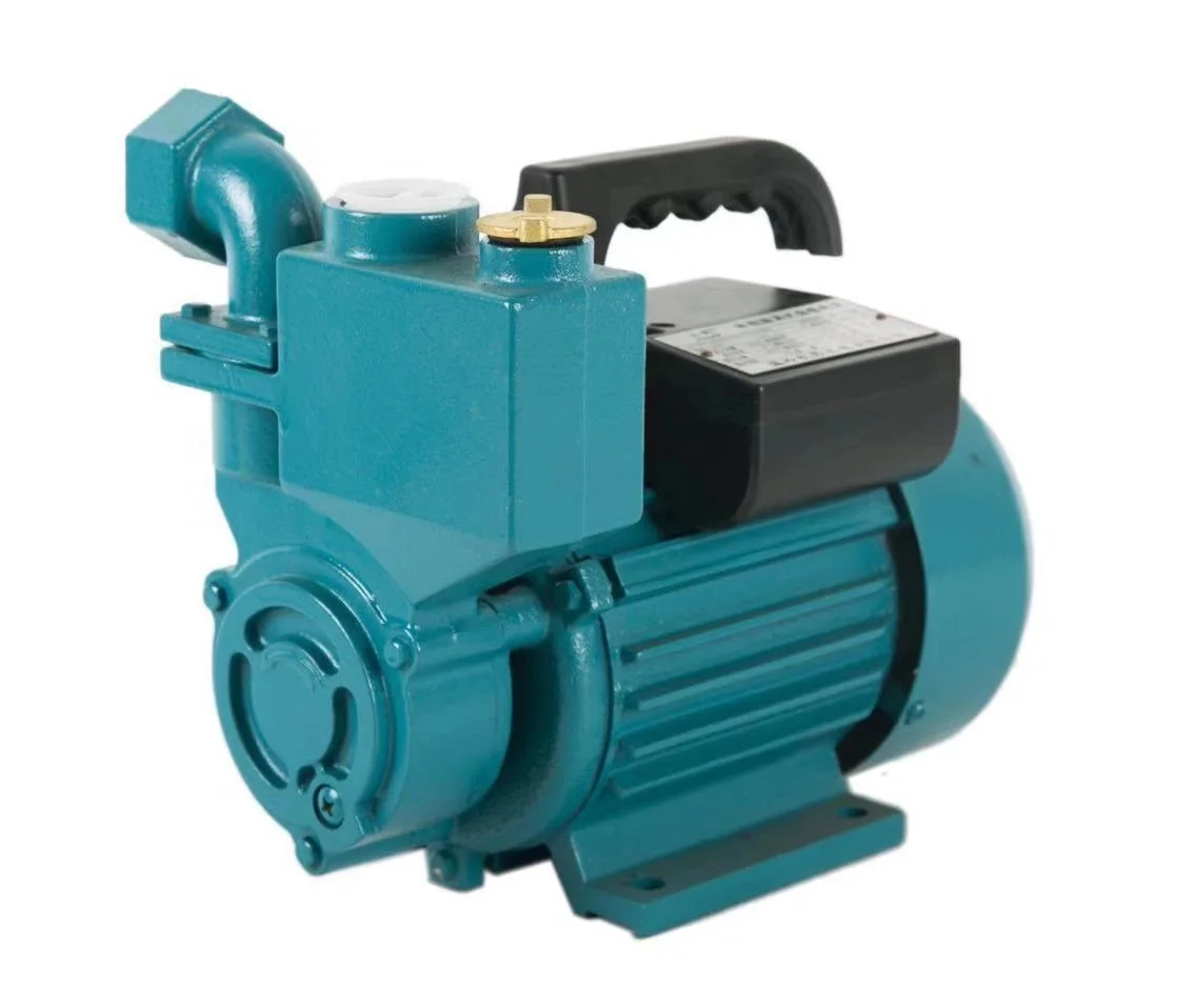
Typically, a liquid pump can"t simply draw air. The feed line of the pump and the internal body surrounding the pumping mechanism must first be filled with the liquid that requires pumping: An operator must introduce liquid into the system to initiate the pumping. This is called priming the pump. Loss of prime is usually due to ingestion of air into the pump. The clearances and displacement ratios in pumps for liquids, whether thin or more viscous, usually cannot displace air due to its compressibility. This is the case with most velocity (rotodynamic) pumps — for example, centrifugal pumps. For such pumps, the position of the pump should always be lower than the suction point, if not the pump should be manually filled with liquid or a secondary pump should be used until all air is removed from the suction line and the pump casing.
Positive–displacement pumps, however, tend to have sufficiently tight sealing between the moving parts and the casing or housing of the pump that they can be described as self-priming. Such pumps can also serve as priming pumps, so-called when they are used to fulfill that need for other pumps in lieu of action taken by a human operator.
One sort of pump once common worldwide was a hand-powered water pump, or "pitcher pump". It was commonly installed over community water wells in the days before piped water supplies.
In parts of the British Isles, it was often called the parish pump. Though such community pumps are no longer common, people still used the expression parish pump to describe a place or forum where matters of local interest are discussed.
Because water from pitcher pumps is drawn directly from the soil, it is more prone to contamination. If such water is not filtered and purified, consumption of it might lead to gastrointestinal or other water-borne diseases. A notorious case is the 1854 Broad Street cholera outbreak. At the time it was not known how cholera was transmitted, but physician John Snow suspected contaminated water and had the handle of the public pump he suspected removed; the outbreak then subsided.
Modern hand-operated community pumps are considered the most sustainable low-cost option for safe water supply in resource-poor settings, often in rural areas in developing countries. A hand pump opens access to deeper groundwater that is often not polluted and also improves the safety of a well by protecting the water source from contaminated buckets. Pumps such as the Afridev pump are designed to be cheap to build and install, and easy to maintain with simple parts. However, scarcity of spare parts for these type of pumps in some regions of Africa has diminished their utility for these areas.
Multiphase pumping applications, also referred to as tri-phase, have grown due to increased oil drilling activity. In addition, the economics of multiphase production is attractive to upstream operations as it leads to simpler, smaller in-field installations, reduced equipment costs and improved production rates. In essence, the multiphase pump can accommodate all fluid stream properties with one piece of equipment, which has a smaller footprint. Often, two smaller multiphase pumps are installed in series rather than having just one massive pump.
A rotodynamic pump with one single shaft that requires two mechanical seals, this pump uses an open-type axial impeller. It is often called a Poseidon pump, and can be described as a cross between an axial compressor and a centrifugal pump.
The twin-screw pump is constructed of two inter-meshing screws that move the pumped fluid. Twin screw pumps are often used when pumping conditions contain high gas volume fractions and fluctuating inlet conditions. Four mechanical seals are required to seal the two shafts.
These pumps are basically multistage centrifugal pumps and are widely used in oil well applications as a method for artificial lift. These pumps are usually specified when the pumped fluid is mainly liquid.
A buffer tank is often installed upstream of the pump suction nozzle in case of a slug flow. The buffer tank breaks the energy of the liquid slug, smooths any fluctuations in the incoming flow and acts as a sand trap.
As the name indicates, multiphase pumps and their mechanical seals can encounter a large variation in service conditions such as changing process fluid composition, temperature variations, high and low operating pressures and exposure to abrasive/erosive media. The challenge is selecting the appropriate mechanical seal arrangement and support system to ensure maximized seal life and its overall effectiveness.
Pumps are commonly rated by horsepower, volumetric flow rate, outlet pressure in metres (or feet) of head, inlet suction in suction feet (or metres) of head.
From an initial design point of view, engineers often use a quantity termed the specific speed to identify the most suitable pump type for a particular combination of flow rate and head.
The power imparted into a fluid increases the energy of the fluid per unit volume. Thus the power relationship is between the conversion of the mechanical energy of the pump mechanism and the fluid elements within the pump. In general, this is governed by a series of simultaneous differential equations, known as the Navier–Stokes equations. However a more simple equation relating only the different energies in the fluid, known as Bernoulli"s equation can be used. Hence the power, P, required by the pump:
where Δp is the change in total pressure between the inlet and outlet (in Pa), and Q, the volume flow-rate of the fluid is given in m3/s. The total pressure may have gravitational, static pressure and kinetic energy components; i.e. energy is distributed between change in the fluid"s gravitational potential energy (going up or down hill), change in velocity, or change in static pressure. η is the pump efficiency, and may be given by the manufacturer"s information, such as in the form of a pump curve, and is typically derived from either fluid dynamics simulation (i.e. solutions to the Navier–Stokes for the particular pump geometry), or by testing. The efficiency of the pump depends upon the pump"s configuration and operating conditions (such as rotational speed, fluid density and viscosity etc.)
For a typical "pumping" configuration, the work is imparted on the fluid, and is thus positive. For the fluid imparting the work on the pump (i.e. a turbine), the work is negative. Power required to drive the pump is determined by dividing the output power by the pump efficiency. Furthermore, this definition encompasses pumps with no moving parts, such as a siphon.
Pump efficiency is defined as the ratio of the power imparted on the fluid by the pump in relation to the power supplied to drive the pump. Its value is not fixed for a given pump, efficiency is a function of the discharge and therefore also operating head. For centrifugal pumps, the efficiency tends to increase with flow rate up to a point midway through the operating range (peak efficiency or Best Efficiency Point (BEP) ) and then declines as flow rates rise further. Pump performance data such as this is usually supplied by the manufacturer before pump selection. Pump efficiencies tend to decline over time due to wear (e.g. increasing clearances as impellers reduce in size).
When a system includes a centrifugal pump, an important design issue is matching the head loss-flow characteristic with the pump so that it operates at or close to the point of its maximum efficiency.
Most large pumps have a minimum flow requirement below which the pump may be damaged by overheating, impeller wear, vibration, seal failure, drive shaft damage or poor performance.
The simplest minimum flow system is a pipe running from the pump discharge line back to the suction line. This line is fitted with an orifice plate sized to allow the pump minimum flow to pass.
A more sophisticated, but more costly, system (see diagram) comprises a flow measuring device (FE) in the pump discharge which provides a signal into a flow controller (FIC) which actuates a flow control valve (FCV) in the recycle line. If the measured flow exceeds the minimum flow then the FCV is closed. If the measured flow falls below the minimum flow the FCV opens to maintain the minimum flowrate.
As the fluids are recycled the kinetic energy of the pump increases the temperature of the fluid. For many pumps this added heat energy is dissipated through the pipework. However, for large industrial pumps, such as oil pipeline pumps, a recycle cooler is provided in the recycle line to cool the fluids to the normal suction temperature.oil refinery, oil terminal, or offshore installation.
Engineering Sciences Data Unit (2007). "Radial, mixed and axial flow pumps. Introduction" (PDF). Archived from the original (PDF) on 2014-03-08. Retrieved 2017-08-18.
Tanzania water Archived 2012-03-31 at the Wayback Machine blog – example of grassroots researcher telling about his study and work with the rope pump in Africa.
C.M. Schumacher, M. Loepfe, R. Fuhrer, R.N. Grass, and W.J. Stark, "3D printed lost-wax casted soft silicone monoblocks enable heart-inspired pumping by internal combustion," RSC Advances, Vol. 4, pp. 16039–16042, 2014.
"Radial, mixed and axial flow pumps" (PDF). Institution of Diploma Marine Engineers, Bangladesh. June 2003. Archived from the original (PDF) on 2014-03-08. Retrieved 2017-08-18.
Quail F, Scanlon T, Stickland M (2011-01-11). "Design optimisation of a regenerative pump using numerical and experimental techniques" (PDF). International Journal of Numerical Methods for Heat & Fluid Flow. 21: 95–111. doi:10.1108/09615531111095094. Retrieved 2021-07-21.
Rajmane, M. Satish; Kallurkar, S.P. (May 2015). "CFD Analysis of Domestic Centrifugal Pump for Performance Enhancement". International Research Journal of Engineering and Technology. 02 / #02. Retrieved 30 April 2021.
Wasser, Goodenberger, Jim and Bob (November 1993). "Extended Life, Zero Emissions Seal for Process Pumps". John Crane Technical Report. Routledge. TRP 28017.
Donald Routledge Hill, "Mechanical Engineering in the Medieval Near East", cf. Donald Hill, Mechanical Engineering Archived 25 December 2007 at the Wayback Machine)
Australian Pump Manufacturers" Association. Australian Pump Technical Handbook, 3rd edition. Canberra: Australian Pump Manufacturers" Association, 1987. ISBN 0-7316-7043-4.

It operates according to the principle of positive movement. It transmit energy to the pumped liquid by 2 rotating geared wheels and are suitable for lifting liquid to a maximum of 8 meters suction.
Rotary Gear Pump, Gear Pump, SS Gear Pump, Crude Oil Pump, Gear Oil pump, Oil Pump, Bitumen Gear Pump, Fuel Injection Gear Pump, LDO pump, Diesel Pump
Wang C., Shi W., Wang X., Jiang X., Yang Y., Li W., Zhou L., Optimal design of multistage centrifugal pump based on the combined energy loss model and computational fluid dynamics. Applied Energy, 2017, 187: 10–26.
Wang C., Hu B., Zhu Y., Wang X., Luo C., Cheng L., Numerical study on the gas-water two-phase flow in the self-priming process of self-priming centrifugal pump. Processes, 2019, 7(6): 330.
Wang C., He X., Zhang D., et al., Numerical and experimental study of the self-priming process of a multistage self-priming centrifugal pump. International Journal of Energy Research, 2019. https://doi.org/10.1002/er.4497.
Wang C., He X., Shi W., et al., Numerical study on pressure fluctuation of a multistage centrifugal pump based on whole flow field. AIP Advances, 2019, 9: 035118. https://doi.org/10.1063/1.5049196.
Chang H., Li W., Shi W., et al., Effect of blade profile with different thickness distribution on the pressure characteristics of novel self-priming pump. Journal of the Brazilian Society of Mechanical Sciences and Engineering, 2018, 40: 518.
Chang H., Shi W., Li W., et al., Energy loss analysis of novel self-priming pump based on the entropy production theory. Journal of Thermal Science, 2018, 28(2): 306–318.
Chang H., Li W., Shi W., Influence of blade thickness distribution on the structural dynamic characteristics under part-load condition. Mechanics, 2019, 25(1): 38–43.
Chang H., Agarwal R.K., Li W., Zhou L., Shi W., Numerical and experimental study of a vortex structure and energy loss in a novel self-priming pump. Processes, 2019, 7(10): 701. https://doi.org/10.3390/pr7100701
Wang Y., Han Y., Zhu X., et al., Optimization and experiment on performance of flow-ejecting self-priming pump based on CFD. Transactions of the Chinese Society of Agricultural Engineering, 2016, 32(1): 16–21. (in Chinese)
Hong L., Yang X., Lei L., et al., Design of sprinkler-drip dual-purpose self-priming pump based on design of experiment. Transactions of the Chinese Society of Agricultural Engineering, 2014, 30(15): 93–97. (in Chinese)
Liu J.R., Xiang H.J., Liu L.L., et al., A numerical analysis of the impact of impeller geometric parameters on self-sunction performance of self-priming pumps. China Rural Water & Hydropower, 2012, 2: 90–93. (in Chinese)
Wang C., Large eddy simulation on interior flow field of rotational flow self-priming pump. Transactions of the Chinese Society for Agricultural Machinery, 2009, 40: 68–67. (in Chinese)
Sun Y.B., Tao C., Shuai Y., et al., Improvement design of hydraulic components and structure of vertical self-priming pump. Journal of Zhejiang University, 2013, 47(2): 332–338.
Xu Y., Tan L., Cao S., et al., Multiparameter and multiobjective optimization design of centrifugal pump based on orthogonal method. ARCHIVE Proceedings of the Institution of Mechanical Engineers Part C Journal of Mechanical Engineering Science 1989–1996, 2016, 231(14): 2569–2579.
Tan L., Cao S., Wang Y., et al., Direct and inverse iterative design method for centrifugal pump impellers. Proceedings of the Institution of Mechanical Engineers Part A Journal of Power & Energy, 2012, 226(6): 764–775.
Liu Y., Tan L., Hao Y., et al., Energy performance and flow patterns of a mixed-flow pump with different tip clearance sizes. Energies, 2017, 10(2): 191.
Hao Y., Tan L., Liu Y., et al., Energy performance and radial force of a mixed-flow pump with symmetrical and unsymmetrical tip clearances. Energies, 2017, 10(1): 57.
Jeon S.Y., Kim C.K., Lee S.M., et al., Performance enhancement of a pump impeller using optimal design method. Journal of Thermal Science, 2017, 26(2): 119–124.
Zheng L., Dou H.S., Chen X., et al., Pressure fluctuation generated by the interaction of blade and tongue. Journal of Thermal Science, 2018, 27(1): 8–16.
Jia X., Cui B., Zhu Z., et al., Numerical investigation of pressure distribution in a low specific speed centrifugal pump. Journal of Thermal Science, 2018, 27(1): 25–33.
He X., Liu J., Guo C., et al., Design and test of desulfurization pump for coal-fired power plant based on acid-rain prevention. Disaster Advances, 2012, 5(4): 1010–1015.
Zhou J., Ren J., Yao C., Multi-objective optimization of multi-axis ball-end milling Inconel 718 via grey correlational analysis coupled with RBF neural network and PSO algorithm. Measurement, 2017, (102): 271–285.
Si Q., Yuan S., Yuan J., et al., Multi-objective optimization of low-specific-speed multistage pumps by using matrix analysis and CFD method. Journal of Applied Mathematics, 2013, 10(4): 261–274.
Wang Y., Huang Y., Zeng X., et al., Faulty feeder detection of single phase-earth fault using grey correlation degree in resonant grounding system. IEEE Transactions on Power Delivery, 2017, 32(1): 55–61.
Zhou Y., Wang D., Zhou H., Speed control of boiler feed water pump turbine based on gray correlation compensation. Journal of Mechanical Science & Technology, 2017, 31(1): 437–444.

Dynex manufactures hydraulic components and systems for use on mobile and industrial machinery. These pumps, valves, motors and power units have been sold worldwide for over 60 years. Products include high-pressure piston pumps, high-pressure directional and pressure control valves, heavy-duty piston motors for demanding conditions, and electrohydraulic actuators for remote control. Dynex also builds standard hydraulic power units or specialized systems for demanding conditions including high pressure and special fluids.

Oil pump manufacturer China Kemai Co.,ltd, main products are gear oil pumps, centrifugal oil pumps. Used for transfer gasoline, diesel, kerosene, crude oil,Cooking oil etc.
MKx gear pump units include a pressure-regulating valve and pressure-relief valve. Electrical pressure monitoring is performed by an integrated pressure switch, and fill-level monitoring also is possible. ...
Featuring an upgraded motor design, the Lincoln EOP2 pump is suitable for use with direct-operating, electrically driven, single-line centralized lubrication systems and delivers reliable performance at a competitive ...
GA Series gear pumps have long been workhorses in highly viscous applications within a multitude of industries due to their dependability, efficiency and low total life cycle costs. Engineered to reliably ...
Gear metering pumps are extremely versatile. Each version is available with different pump clearances, making them suitable for metering low to high-viscosity ...
This simple pump uses tube elements and Luer connectors for easy fitting and replacement, particularly when mounted inside instruments. Tubing is fully enclosed in the housing. Supported by ball bearings, the pump ...
Gear Pumps are designed primarily for metering and transfer applications. Their modular design allows a wide variation of flow ranges with a standard parts set. Gear Pumps ...
Wet-installed horizontal propeller pump with submersible motor, equipped with direct drive or spur gear, ECB propeller with rigid, fibre-repellent blades, bolt-free connection to the discharge pipe. Explosion-proof ...
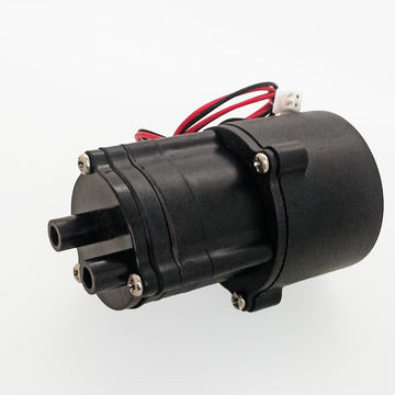
Johnson Electric utilizes its wide range of DC Motor, Synchronous and EC Motor technologies to develop customized impeller mechanisms which generate high power, high efficiency, low noise subsystems. Platform modules are available to ...
The new Johnson Pump TopGear Bloc close-coupled gear pumps in cast iron and stainless steel utilize the proven hydraulics of the TopGear range. For low/medium-viscous, clean and non-abrasive ...
... The Garda AC pump, suitable for the transfer of water, diesel and oil, consists of a gear pump that ensures greater power during transfer, in the event that the liquid being delivered ...
... needs to be transferred by a reliable and safe oil transfer pump. The PIUSI Viscomat DC gear oil pump is capable of supporting a thick oil with any working lock. To ensure greater reliability, ...
Gear pumps with pressure switch. The “Viscomat” is designed to satisfy requirements of constant flow deliveries with a self-priming pump featuring automatic switch-off on the completion ...
Viking Pump® is the leader in internal gear innovation and the latest development is the O-Pro® seal technology. This new series benefits from the enhancement of our own factory engineered and installed ...
The QXV series has been developed for use with low-viscosity fluids. QXV pumps have proven particularly successful in applications for pumping kerosene, automotive fuels, paraffin, brake fluids and many other low-viscosity ...
ELI2 is the first release of the ELIKA product line and includes pumps with displacements from 7 to 35 cm 3 /rev; perfectly interchangeable with our standard gear pumps in the ALP2 and ...
With the built-in central valve design, the plunger pumps of M Series also have high volumetric efficiencies at high pressures. The carbide plungers used are extremely robust, provide long service life at very high pressures ...
... plunger pumps of the Z series deliver operating pressures up to 1,500 bar. With a high number of pressure and nominal flow rate combinations, the pumps are preferably used in industrial cleaning, paint ...
2000 pumps set the standard in positive displacement pumping applications. The proprietary 2000 gear-type universal joint design effectively handles radial and thrust loads for maximum performance and ...
... are decisive for the quality of the end product. The KF 0 stainless steel gear pump is particularly suitable for these applications. The KF 0 stainless steel is an external gear pump ...
KF series gear pumps are external gear pumps that operate according to the positive displacement principle. Here, the fluid is transported from the suction to the discharge ...
... components. The KF-F fuel pumps are durable up to a WSD value of 520 µm, which is the minimum lubricity of MGO and DMA according to ISO 8217. Furthermore, the pumps exhibit extremely good efficiency, ...

The hydraulic pump is an energy conversion device, which converts the mechanical energy of the driving motor into the pressure energy of the oil to meet the needs of the actuator to drive the external load.
The main performances of commonly used hydraulic pumps are shown in Table.PerformanceExternal gear pumpDouble-acting vane pumpPressure-limiting variable vane pumpRadial Piston PumpAxial piston pumpScrew pump
The principle of selecting the hydraulic pump is: according to the working condition of the main engine, the size of the power and the performance requirements of the system, first determine the type of the hydraulic pump, and then determine its specification and model according to the pressure and flow required by the system.For general machine tool hydraulic systems, double-acting vanepumps, and pressure-limiting variable vane pumps are often used; while road construction machinery, port machinery, and small construction machinery, gear pumps with strong anti-pollution capabilities are often selected; In occasions, plunger pumps are often chosen.
Pay attention to whether the flow of the hydraulic pump is adjustable. Generally speaking, if the hydraulic power is less than 10kW, the working cycle is on-off, the hydraulic pump can be completely unloaded when not in use, and the hydraulic pump is required to output full flow under most working conditions, you can consider using a fixed pump; if the hydraulic power If the flow rate is larger than 10KW, the variable pump can be considered.
Pay attention to parallel pumps and series pumps. Gear pumps and vane pumps can also be made into several pumps connected in parallel, and use a double pump or triple pump with the same drive shaft, or can be connected in series to form a multi-stage pump. When the hydraulic system-the flow rate changes greatly within a working cycle, multiple pumps can be used. Multiple pumps usually have one oil suction port and multiple oil outlets. The pressure oil from each oil outlet can supply oil to different actuators of the system, or can be combined to supply a certain actuator.
The maximum working pressure Pp of the hydraulic pump depends on the maximum working pressure of the actuator (hydraulic cylinder or hydraulic motor), namely
If the oil supply of the hydraulic pump is selected according to the working conditions (for example, when two pumps are used for oil supply, the small flow pump supplies the flow of the working conditions), the minimum overflow of the overflow valve should also be considered when calculating the oil supply.
The pressure of the hydraulic pump obtained by the above calculation is the static pressure of the system. In the dynamic working process of the system, the dynamic pressure of the system far exceeds the static pressure due to pressure overshoot or periodic pressure pulsation during the transition process. Therefore, when selecting a hydraulic pump, the rated pressure of the hydraulic pump should be 25%~60% higher than the maximum calculated pressure of the system (a high-pressure system takes a small value, medium and the low-pressure system takes the larger value) so that the hydraulic pump has a certain pressure reserve.Generally speaking, in fixed equipment, the rated pressure of the hydraulic pump should be about 25% higher than the normal working pressure, and the rated pressure of the hydraulic pump for vehicles should be about 45% higher than the normal working pressure to ensure the pump has a sufficient life. If the reliability requirements of the hydraulic system are particularly high, the rated working pressure of the hydraulic pump can be selected higher.
If the hydraulic system only requires the supply of high-pressure and small-flow working medium in a short period, the maximum working pressure of the hydraulic pump can be selected smaller at this time (when selecting a hydraulic pump, it is not advisable to reduce the specifications of the large-capacity hydraulic pump. It is because when the working pressure and working flow of the hydraulic pump are less than its rated value, the overall efficiency of the hydraulic pump will decrease).
The highest working pressure on the sample is the allowable pressure during short-term impact. Do not have impact pressure in every cycle, otherwise, the life of the hydraulic pump will be significantly shortened or even damaged.
As for the flow rate of the hydraulic pump, the maximum flow rate required by the system can be selected when selecting, and it should not exceed too much to avoid excessive power loss. After the structure of the hydraulic pump is drawn up, the specifications and models of the hydraulic pump can be determined by referring to the relevant technical manuals or product samples according to the maximum working pressure and maximum output flow of the hydraulic pump.
In the actual selection, because the pump displacement, speed range, and output flow under different pressures at typical speed are usually given on the product sample. Therefore, when the required flow qv
qp=Vnηv×10-3The output flow of the hydraulic pump should include the flow required by the actuator (the total flow can be obtained from the time chart when there are multiple actuators), the minimum overflow flow of the overflow valve, the sum of the leakage of each component, and the motor reverse rotation (usually 1r/s or so), the flow reduction caused by the reduction in efficiency of the hydraulic pump after long-term use (usually 5% to 7%).
The flow rate of the hydraulic pump is related to the working condition, and the maximum flow rate of the hydraulic pump is determined by the maximum flow rate in the system working condition diagram. When selecting the flow rate of the hydraulic pump, it should not be less than or equal to the maximum flow rate when the hydraulic system is working.
The flow rate of the hydraulic pump is related to the speed of the prime mover. When the prime mover and the hydraulic pump are connected by a coupling, the speed of the prime mover should be within the working speed range of the hydraulic pump, otherwise, a speed increasing or decelerating device should be installed between the prime mover and the hydraulic pump.
The higher the pressure and the lower the speed, the lower the volumetric efficiency of the hydraulic pump, and the volumetric efficiency of the variable pump will decrease when the displacement of the variable pump is adjusted. When the speed is constant, the total efficiency of the hydraulic pump is the highest at a certain pressure, and the total efficiency of the variable pump is the highest at a certain displacement and a certain pressure. The total efficiency of the hydraulic pump has a great influence on the efficiency of the hydraulic system. Therefore, it is taboo to choose a low-efficiency hydraulic pump. You should choose a high-efficiency hydraulic pump, and try to make the hydraulic pump work in an efficient working condition area.
Consider the problem from the perspective of improving energy conversion efficiency. Don’t just consider the rated working conditions, but should make the efficient working range as wide as possible. When choosing a hydraulic pump, do not reduce the specification of a large-capacity pump. This is because when the pump’s working pressure and working flow are less than its rated value, the overall efficiency of the pump will decrease. Generally speaking, the volumetric efficiency of the hydraulic pump is more important than the mechanical efficiency. Because the hydraulic pump can obtain power from the prime mover to compensate for the mechanical friction loss, but the leakage loss in the hydraulic pump cannot be compensated by increasing the power input. Of course, the rotational speed of the hydraulic pump should not be too high or too low, otherwise, its mechanical efficiency will decrease. It is generally believed that when the hydraulic pump works in the range of 1000~1800r/min, it has little effect on the overall efficiency.
In the case of using an engine to drive the hydraulic pump, low speed is prohibited when the oil temperature is low, otherwise, it will be difficult to absorb oil, and there will be a risk of seizing failure due to poor lubrication; at high speeds, cavitation, vibration, abnormal wear, and flow must be considered The possibility of instability and other phenomena, to avoid drastic changes in the speed of the hydraulic pump from having a huge impact on the strength of the internal parts of the hydraulic pump.
If the pressure and flow rate of the pump are relatively constant during the working cycle (that is, the p-t curve and q-t curve on the working condition diagram change more smoothly), then the hydraulic pump drive power Pp Should be calculated as follows
Hydraulic pumps of fixed equipment are usually driven by electric motors. According to the power calculated above and the rotational speed of the hydraulic pump and its use environment, select its model specifications from the product catalog or manual (rated power, rotational speed, power supply, structure (vertical, horizontal, open, closed, etc.) ], and calculate the overload capacity to ensure that the peak overload of the motor is less than 25%~50% in each working stage.
Since the hydraulic pump usually starts under no load, there is no excessively high requirement on the starting torque of the motor, the load changes relatively smoothly, and the number of starts is small, so a cage-type three-phase asynchronous motor can be used. But if the power of the hydraulic system is large and the grid capacity is not large, a wound rotor motor can be used. For hydraulic pumps that adopt variable frequency flow adjustment schemes, AC asynchronous motors controlled by variable frequency speed regulation or electromagnetic speed regulation should be used to drive the hydraulic pump.
Motors of the same type with the same capacity (power) usually have different speeds for selection. Low-speed motors have a large number of magnetic poles, large dimensions and weights, high prices, and require pumps with a large displacement (under a certain flow rate), while high-speed motors are the opposite. Therefore, the speed of the motor should be considered comprehensively with the flow and displacement of the pump.
The working environment of the hydraulic pump is different, and the protection form of its drive motor is required to be different: an open motor (protection mark is IP11) should be used in a clean and dry environment; a protective motor should be used in a cleaner and clean environment (protection mark is IP22 and IP23) drive; humid, dusty, high temperature, corrosive or weather-prone environments should be driven by enclosed motors (protection mark IP44); explosion-proof motors should be used in explosive environments.
When the hydraulic pump is driven by an internal combustion engine, in one case, the hydraulic pump is only a part of the internal combustion engine’s drive load; in another case, the entire power of the internal combustion engine is used to drive the hydraulic pump. In the former, the power of the internal combustion engine is large, which can always meet the power required by the hydraulic pump. The speed of the internal combustion engine should match the optimal speed of the hydraulic pump. High-speed internal combustion engines usually have a deceleration device to make the hydraulic pump work within the optimal speed range. In the latter, the system in which the entire power of the internal combustion engine is used to drive the hydraulic pump is called a full hydraulic drive system. The full hydraulic drive system usually adopts a variable pump or variable motor volumetric speed control system to meet the requirements of large changes in the speed of mobile machinery. The maximum speed of the internal combustion engine should meet the maximum flow required by the system and not exceed the maximum allowable speed of the hydraulic pump. If the engine speed is too high, a deceleration device should be installed. The maximum power of the internal combustion engine should be slightly greater than the maximum power required by the hydraulic system.
A closed hydraulic system that uses a manual servo variable pump to control the commutation of the actuator should avoid self-priming and oil replenishment. As shown in Figure 1-1, in the process of using a manual servo variable pump to control the commutation of the actuator, the variable mechanism of the servo variable pump must pass the zero position (that is, the position when the variable pump has no flow output). The variable mechanism of the pump is set to zero. From the variable principle of the servo variable pump, it is known that pressure oil must be available to realize the variable. However, when the variable mechanism is in the zero position, no pressure oil can be generated when the self-priming oil is used.
Note that corresponding measures should be taken to form a closed hydraulic system with a variable pump and a single-rod hydraulic cylinder. In Figure 1-2, the variable pump and the single-rod hydraulic cylinder form a closed hydraulic system. When the piston rod is extended, there will be no problem. When the piston rod is retracted, the hydraulic cylinder discharges more oil than it enters. The amount is much larger. If no measures are taken, the hydraulic cylinder cannot move at this time.
When the hydraulic motor is operating as a hydraulic pump, avoid the main pump from being subjected to working pressure difference. Figure 1-3 In a closed system composed of a variable pump and a hydraulic motor, when the variable mechanism of the variable pump is set to zero, the motor operates as a meter under the action of external power. Adjusting the overflow valve can control the motor to operate as a pump. The working pressure difference also acts on the main pump, but at this time, the variable mechanism of the main pump is set to zero as a stop valve. However, the high pressure cavity of the main pump has to bear high-pressure, and the relevant parts of the high-pressure cavity are equivalent to bear static high pressure, which is very disadvantageous. In addition, when the variable mechanism of the main pump deviates from zero due to vibration and other reasons, the system pressure will suddenly drop and cause an accident.
When designing the pump-motor closed system, pay attention to the situation of heavy objects falling at the moment of driving. As shown in Figure 1-3, the heavy lifting closed system is composed of a hydraulic pump and hydraulic motor. When the brake of the motor is released, the heavy object forms an excess torque to drive the hydraulic motor to rotate, so that the hydraulic motor is in working condition of the hydraulic pump. With the increase of the falling speed of the weight, once the torque of the pressure oil at the motor outlet is not enough to balance with the load torque of the weight acting on the hydraulic motor, the falling speed of the weight will be out of control, causing a crash accident. Because the pressure built up by the heavy object causes oil compression and oil leakage, which are the main reasons for the sliding of the heavy object at the moment of driving, a one-way valve can be installed in the high-pressure pipeline of the system close to the hydraulic motor to connect the hydraulic motor with other The components are separated, and the pressure signal of the heavy object can also be used to control the variable mechanism of the hydraulic pump so that the outlet pressure of the hydraulic pump automatically tracks the pressure established by the weight at the motor outlet so that the sliding speed of the heavy object can be significantly reduced at the moment of driving. The sliding distance is greatly reduced, and the working reliability of the hydraulic system is also improved.
The variable pump determines the amount of oil supplement for the closed system of the main pump. In a closed system where the variable pump is the main pump, it is inevitable to supplement the oil. However, only the actual flow rate of the variable pump in the system is used as the basis for determining the replenishment, which sometimes results in insufficient replenishment. If the rated speed of the variable pump is 1500r/min, and the speed of the variable pump in the system is only 1000r/min, or the actual maximum flow of the system variable pump is only 90% of the rated flow of the pump, etc., insufficient oil supplement will occur. Hidden dangers. Of course, when determining the replenishment amount of a closed hydraulic system, the leakage caused by pipelines, valves, and actuators still needs to be considered.
The oil in the replenishment circuit should not be returned to the oil without cooling. If the oil in the replenishing circuit uses uncooled return oil, the temperature of the system oil will rise, which will adversely affect the system. If the leakage in the compon


 8613371530291