
priming tractor hydraulic pump manufacturer

TRADEMARK DISCLAIMER: Tradenames and Trademarks referred to within Yesterday"s Tractor Co. products and within the Yesterday"s Tractor Co. websites are the property of their respective trademark holders. None of these trademark holders are affiliated with Yesterday"s Tractor Co., our products, or our website nor are we sponsored by them. John Deere and its logos are the registered trademarks of the John Deere Corporation. Agco, Agco Allis, White, Massey Ferguson and their logos are the registered trademarks of AGCO Corporation. Case, Case-IH, Farmall, International Harvester, New Holland and their logos are registered trademarks of CNH Global N.V.

The gear pump is a PD (Positive displacement) pump. It helps to develop a flow by carrying the fluid between repeatedly enclosing interlocking gears or cogs, transferring it automatically using a cyclical pumping action. So, the Gear pump provides a smooth pulseless fluid flow of which rate depends on its gears’ rotational speed.
The gear pump uses the rotating gears or cogs’ action to move fluids. Its rotating part forms a fluid seal by the casing of the pump and creates the suction at the inlet of the gear pump. Fluid pulled into a gear pump is surrounded within the rotating gears or cogs cavities and shifted out to discharge.
External design Gear pump contains two identical and interlocking gears that are supported through separate shafts. The motor is used to drive the first gear which drives the second gear. In a few cases, electrical motors can drive both shafts that are supported with bearings on every side of the casing.When gears move out from the mesh on the pump’s inlet side, they form an extended volume, Fluid flows into the pump’s cavities and entrapped by the edges of gear while gears carry on rotating against the casing of the pump.
The fluid cannot be transferred back over the center, amongst the gears, as they got connected. Close tolerances amongst the casing and the gears let the external gear pump to extend suction over the inlet and prohibit fluid from going back from the pump’s discharge side (Though the low viscosity fluids have more tendency for fluid leakage).
The Internal Design Gear Pump works the same as of External Design Gear Pump except that it’s both interconnected gears have different sizes where one rotates inside of others. It has a larger internal gear which is called the rotor i.e. its edges projecting from the inside. The other external gear of small size mounted into the center of the rotor which is called the idler. It is designed for interconnecting with the outer rotor in a way that edges of gear engage at the one end. The bushing along with a pinion is attached to the casing of the pump which holds inner idle into its location. A crescent shape fixed divider fills the vacant place which is created by the idler’s irregular mounting position. It works like the seal amongst outlet & inlet ports.When gears move out from the mesh on the pump’s inlet side, they form an extended volume, fluid flows into the pump’s cavities, and entrapped by the edges of gear while gears carry on rotating against the partition and casing of the pump.
The gear pump has few moving parts and is very simple and compact. Its pressure power cannot be matched with reciprocating pumps or the rates of flow of the centrifugal pumps. Yet it provides higher throughputs and pressures than lobe pumps or vanes. The gear pump is specifically suitable for fluids of high viscosity and pumping oils.
From the two types of gear pump, the external design has the ability to sustain high flow rates and pressures (more than 3000psi) due to its closer tolerances and stronger shaft support. Internal design provides better suction. It is suitable for fluids of high viscosity but it provides an operating range of 1cp to more than 1,000,000cp. As output depends on the rotational speed, the gear pump is mostly used for blending and metering operations. The gear pump can also be engineered for handling the aggressive liquids. Whereas it is generally made from stainless steel or cast iron, new composites and alloys let the pump handle the corrosive fluids like sodium hypochlorite, sulphuric acid, sodium hydroxide, and ferric chloride.
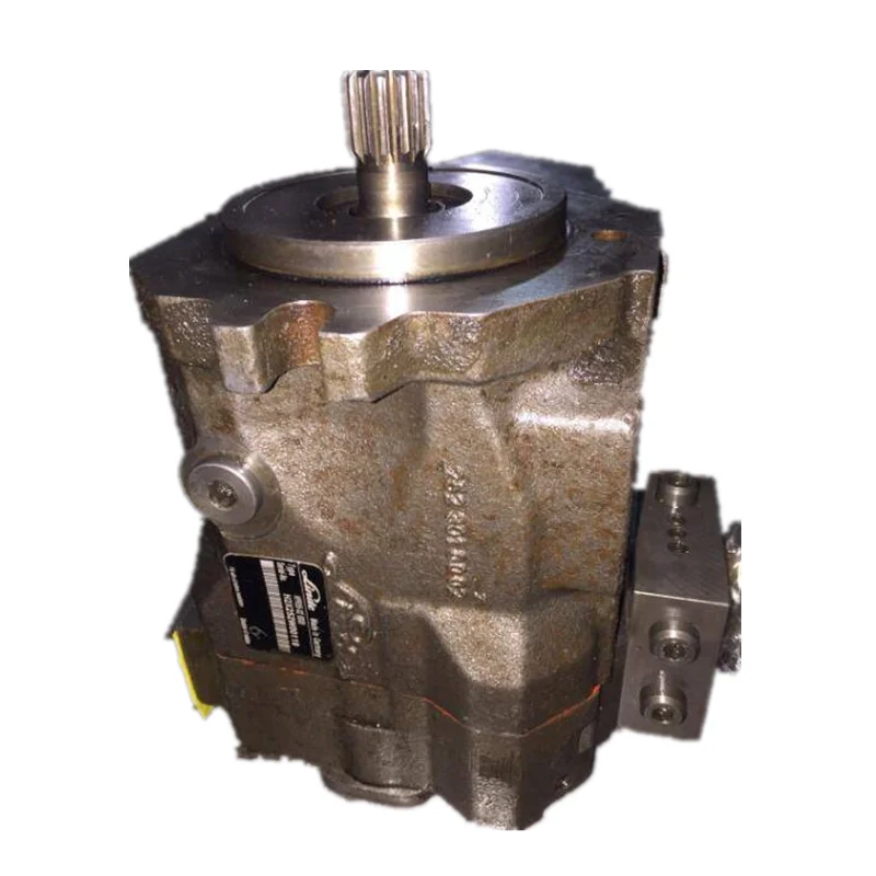
The external design can be used in lifting machinery, hydraulic power, plant equipment, and vehicles. When the gear pump is driven in reverse, by using the oil which can be pumped from anywhere in the system (generally through a tandem pump within an engine), creates the hydraulic motor. It can be beneficial for providing power in those fields where the electrical system is costly, inconvenient, or bulky. For example, a tractor depends on an external design engine-driven gear pump to power its services.
The gear pump is self-priming yet it can also dry lift, though its priming features can be enhanced by wetting the gears. The gears should not run dry for a prolonged period and must be lubricated through a pumped fluid. Some designs of gear pumps can be operated in both directions (forward or reverse). Since the same gear pump can be utilized for loading and unloading the vessel, for instance.
Close tolerance amongst the casing and gear means that this pump type is vulnerable to wear especially when feeds consisting of entrained solids or the abrasive fluids are used. Though, few pump designs, specifically internal variants that let to handle the solids as well. The external design gear pump has four bearings with tight tolerances. Therefore, it is less suitable to handle abrasive fluids. The internal design gear pump is more robust and has just one bearing (maybe two) to run in a fluid. The gear pump needs to install a strainer on a suction side that can protect it from potential damages of solids.
In general, when a gear pump requires for handling abrasive solids then it’s better to choose a pump with higher capacity that can be run at low speed to avoid wear. But it must keep in mind that the gear pump’s volumetric efficiency becomes lessens at low flow rates and speeds. The gear pump must not be run beyond the recommended speed.
In applications of high temperature, it’s necessary to make sure that an operating range of temperature is compatible along with the specification of the pump. Gears and casings’ thermal expansion lessens clearances in the pump which can lead towards increased wear as well as in extreme circumstances, pump failure.
In spite of the best precautions, the bearings, casing, and gears of the pump succumb to wearing with every passing day. As there is an increase in clearances, a gradual decrease in efficiency happens along with an increase in the flow slip: pumped fluid’ leakage from the expulsion back towards a suction side. The flow slip depends on the clearance’ cube between the casing and cog edge so, practically, wear provide a small impact till a critical stage is reached after which the performance of the pump degrades rapidly.
Gear pumps continue to pump in contrary to reverse pressure then, if downstream blockage happens, it will carry on to the pressurized system till the pipework, pump, or other parts fails. Due to this reason, some gear pumps are used to equip with the relief valves. It’s advisable to use a relief valve anywhere within a system for protecting the downstream equipment.
The internal designs gear pumps that operated at less speed are considered ideal for the shear-sensitive fluids like paint, soaps, and foodstuffs. The lower clearances and higher speeds of eternal design gears make them appropriate for these kinds of applications. The internal design gear pump also prefers where hygiene conditions are more important due to its mechanical simplicity. This is a fact that it has easy to clean, strip down, and reassemble features.
Gear pumps are appropriate for pumping the fluids of high viscosity like foodstuff, oil, paints, or resins. They are used in any kind of application where the output of high pressure or accurate dosing is required. The gear pump output is not affected too much by pressure and they can be used in any type of situation where irregular supply occurs.
The gear pump helps to develop a flow by carrying the fluid between repeatedly enclosing interlocking gears or cogs, transferring it automatically to smooth pulseless flow of which rate depends on its gears’ rotational speed. Two basic design types of gear pumps are external design and internal design.
External design Gear pump contains two identical and interlocking gears that are supported through separate shafts. The Internal Design Gear Pump has two interconnected gears having different sizes where one rotates inside of others.
Gear pumps are appropriate for pumping the fluids of high viscosity like foodstuff, oil, paints, or resins. They are used in any kind of application where the output of high pressure or accurate dosing is required. The external design gear pump is used to sustain high pressure (more than 7500 psi) while the internal design gear pump provides better suction and is more suitable to fluids which are shear sensitive and of high viscosity.

There are typically three types of hydraulic pump constructions found in mobile hydraulic applications. These include gear, piston, and vane; however, there are also clutch pumps, dump pumps, and pumps for refuse vehicles such as dry valve pumps and Muncie Power Products’ Live PakTM.
The hydraulic pump is the component of the hydraulic system that takes mechanical energy and converts it into fluid energy in the form of oil flow. This mechanical energy is taken from what is called the prime mover (a turning force) such as the power take-off or directly from the truck engine.
With each hydraulic pump, the pump will be of either a uni-rotational or bi-rotational design. As its name implies, a uni-rotational pump is designed to operate in one direction of shaft rotation. On the other hand, a bi-rotational pump has the ability to operate in either direction.
For truck-mounted hydraulic systems, the most common design in use is the gear pump. This design is characterized as having fewer moving parts, being easy to service, more tolerant of contamination than other designs and relatively inexpensive. Gear pumps are fixed displacement, also called positive displacement, pumps. This means the same volume of flow is produced with each rotation of the pump’s shaft. Gear pumps are rated in terms of the pump’s maximum pressure rating, cubic inch displacement and maximum input speed limitation.
Generally, gear pumps are used in open center hydraulic systems. Gear pumps trap oil in the areas between the teeth of the pump’s two gears and the body of the pump, transport it around the circumference of the gear cavity and then force it through the outlet port as the gears mesh. Behind the brass alloy thrust plates, or wear plates, a small amount of pressurized oil pushes the plates tightly against the gear ends to improve pump efficiency.
A cylinder block containing pistons that move in and out is housed within a piston pump. It’s the movement of these pistons that draw oil from the supply port and then force it through the outlet. The angle of the swash plate, which the slipper end of the piston rides against, determines the length of the piston’s stroke. While the swash plate remains stationary, the cylinder block, encompassing the pistons, rotates with the pump’s input shaft. The pump displacement is then determined by the total volume of the pump’s cylinders. Fixed and variable displacement designs are both available.
With a fixed displacement piston pump, the swash plate is nonadjustable. Its proportional output flow to input shaft speed is like that of a gear pump and like a gear pump, the fixed displacement piston pump is used within open center hydraulic systems.
As previously mentioned, piston pumps are also used within applications like snow and ice control where it may be desirable to vary system flow without varying engine speed. This is where the variable displacement piston pump comes into play – when the hydraulic flow requirements will vary based on operating conditions. Unlike the fixed displacement design, the swash plate is not fixed and its angle can be adjusted by a pressure signal from the directional valve via a compensator.
Vane pumps were, at one time, commonly used on utility vehicles such as aerial buckets and ladders. Today, the vane pump is not commonly found on these mobile (truck-mounted) hydraulic systems as gear pumps are more widely accepted and available.
Within a vane pump, as the input shaft rotates it causes oil to be picked up between the vanes of the pump which is then transported to the pump’s outlet side. This is similar to how gear pumps work, but there is one set of vanes – versus a pair of gears – on a rotating cartridge in the pump housing. As the area between the vanes decreases on the outlet side and increases on the inlet side of the pump, oil is drawn in through the supply port and expelled through the outlet as the vane cartridge rotates due to the change in area.
Input shaft rotates, causing oil to be picked up between the vanes of the pump which is then transported to pump outlet side as area between vanes decreases on outlet side and increases on inlet side to draw oil through supply port and expel though outlet as vane cartridge rotates
A clutch pump is a small displacement gear pump equipped with a belt-driven, electromagnetic clutch, much like that found on a car’s air conditioner compressor. It is engaged when the operator turns on a switch inside the truck cab. Clutch pumps are frequently used where a transmission power take-off aperture is not provided or is not easily accessible. Common applications include aerial bucket trucks, wreckers and hay spikes. As a general rule clutch pumps cannot be used where pump output flows are in excess of 15 GPM as the engine drive belt is subject to slipping under higher loads.
What separates this pump from the traditional gear pump is its built-in pressure relief assembly and an integral three-position, three-way directional control valve. The dump pump is unsuited for continuous-duty applications because of its narrow, internal paths and the subsequent likelihood of excessive heat generation.
Dump pumps are often direct mounted to the power take-off; however, it is vital that the direct-coupled pumps be rigidly supported with an installer-supplied bracket to the transmission case with the pump’s weight at 70 lbs. With a dump pump, either a two- or three-line installation must be selected (two-line and three-line refer to the number of hoses used to plumb the pump); however, a dump pump can easily be converted from a two- to three-line installation. This is accomplished by inserting an inexpensive sleeve into the pump’s inlet port and uncapping the return port.
Many dump bodies can function adequately with a two-line installation if not left operating too long in neutral. When left operating in neutral for too long however, the most common dump pump failure occurs due to high temperatures. To prevent this failure, a three-line installation can be selected – which also provides additional benefits.
Pumps for refuse equipment include both dry valve and Live Pak pumps. Both conserve fuel while in the OFF mode, but have the ability to provide full flow when work is required. While both have designs based on that of standard gear pumps, the dry valve and Like Pak pumps incorporate additional, special valving.
Primarily used on refuse equipment, dry valve pumps are large displacement, front crankshaft-driven pumps. The dry valve pump encompasses a plunger-type valve in the pump inlet port. This special plunger-type valve restricts flow in the OFF mode and allows full flow in the ON mode. As a result, the horsepower draw is lowered, which saves fuel when the hydraulic system is not in use.
In the closed position, the dry valve allows just enough oil to pass through to maintain lubrication of the pump. This oil is then returned to the reservoir through a bleed valve and small return line. A bleed valve that is fully functioning is critical to the life of this type of pump, as pump failure induced by cavitation will result if the bleed valve becomes clogged by contaminates. Muncie Power Products also offer a butterfly-style dry valve, which eliminates the bleed valve requirement and allows for improved system efficiency.
It’s important to note that with the dry valve, wear plates and shaft seals differ from standard gear pumps. Trying to fit a standard gear pump to a dry valve likely will result in premature pump failure.
Encompasses plunger-type valve in the pump inlet port restricting flow in OFF mode, but allows full flow in ON mode lowering horsepower draw to save fuel when not in use
Wear plates and shaft seals differ from standard gear pumps – trying to fit standard gear pump to dry valve likely will result in premature pump failure
Live Pak pumps are also primarily used on refuse equipment and are engine crankshaft driven; however, the inlet on a Live Pak pump is not outfitted with a shut-off valve. With a Live Pak pump, the outlet incorporates a flow limiting valve. This is called a Live Pak valve. The valve acts as an unloading valve in OFF mode and a flow limiting valve in the ON mode. As a result, the hydraulic system speed is limited to keep within safe operating parameters.
Outlet incorporates flow limiting valve called Live Pak valve – acts as an unloading valve in OFF mode and flow limiting valve in ON mode restricting hydraulic system speed to keep within safe operating parameters

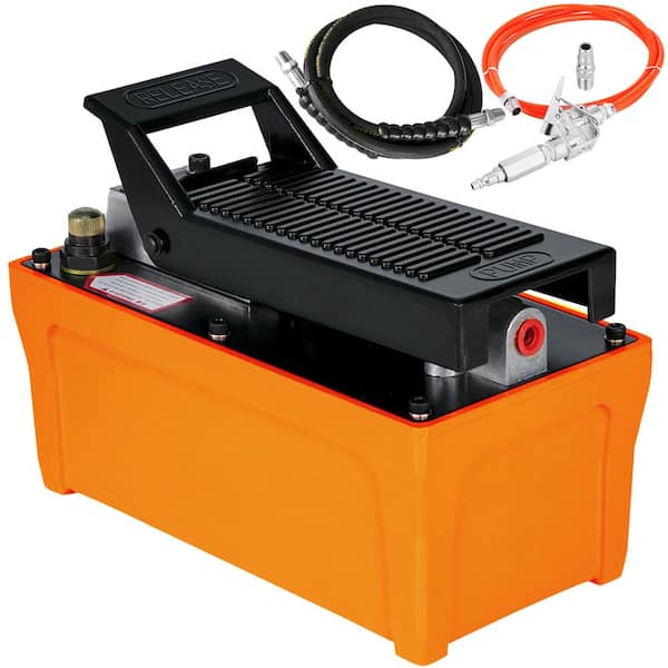
Long story but a good friend lost all hydraulic pressure after cleaning the filter screen on his Mahindra tractor. We felt certain the pump had lost prime so I did a little searching on the net to see what type of fix I might find. Ran across an easy method of using a air hose to pressurize the fluid reservoir in the transmission since the transmission fluid drives the hydraulics as well. Worked like a charm. Not a lot of pressure needed and it�s a fix that works on any tractor with an external pump.

PRIME GUARD Premium Tractor Hydraulic Fluid is a high quality, specially designed lubricant containing anti-rust, anti-foam and oxidation inhibitors; plus, other additives necessary for the wide range of applications recommended by various tractor manufacturers. This product resists thickening in cold weather and thinning in the heat of the summer. It is compounded with detergents to keep transmissions clean and maintain hydraulic control circuits in perfect working condition; and provides excellent protection against seal and pump deterioration.

Ace developed the first hydraulic motor driven pump at the request of John Deere in 1969. Many of the original pumps are still operating today after more than 30 years of service.
Centrifugal pump design provides good resistance to abrasive solutions and extra flow for agitation. The advantages of the hydraulic motor driven pump are mounting versatility, customized performance, and ease of maintenance. All hydraulic driven pumps are equipped with a stainless steel shaft and wear ring for excellent corrosion resistance.MOUNTING VERSATILITY:The location of the pump is not tied to the PTO or engine drive shaft; the pump can be mounted in a variety of locations to suit application requirements.
CUSTOMIZED PERFORMANCE: The performance is dependent on the supply of hydraulic oil to the motor and not necessarily tied to engine speed. A hydraulic driven pump can produce higher pressures than PTO or belt driven pumps. They can also hold constant pressure at varying engine speeds on closed center hydraulic systems.
EASY MAINTENANCE: On a hydraulic driven pump there are no belts to align or break. Separate pump and hydraulic motor shafts simplify repair and replacement. Two main pump bearings support shaft loads. All pumps are equipped with easily replaceable FKM mechanical seals.
The Ace gear type hydraulic motor is more efficient than gerotor type motors, and is less subject to damage by contamination than the gerotor design. A built-in needle valve allows for the bypass of up to 9 GPM excess hydraulic fluid on open center systems. The standard motor has a reverse flow check valve which prevents backward hookup and a coasting check which protects the motor seal from the flywheel effect of the impeller. A restrictor orifice is included with pump models recommended for pressure compensating closed center systems. The Ace Internet Hydraulic Selection Guide is here to help in finding the proper hydraulic pump for your tractor.
The 206 motor requires 7 GPM (26.5 LPM) maximum hydraulic fluid input and fits virtually all tractor hydraulic systems. Recommended for:Pressure Compensating Closed Center Systems
The 206 motor requires 7 GPM (26.5 LPM) maximum hydraulic fluid input and fits virtually all tractor hydraulic systems. Recommended for:Pressure Compensating Closed Center Systems
The 310 motor requires 16 GPM (60.6 LPM) maximum hydraulic fluid input. Recommended for:Large Open Center Systems up to 24 GPM (90.9 LPM) using internal needle valve bypass.
The 206 motor requires 7 GPM (26.5 LPM) maximum hydraulic fluid input and fits virtually all tractor hydraulic systems. Recommended for:Pressure Compensating Closed Center Systems
The 206 motor requires 7 GPM (26.5 LPM) maximum hydraulic fluid input and fits virtually all tractor hydraulic systems. Recommended for:Pressure Compensating Closed Center Systems
The 206 motor requires 7 GPM (26.5 LPM) maximum hydraulic fluid input and fits virtually all tractor hydraulic systems. Recommended for:Pressure Compensating Closed Center Systems
The 206 motor requires 7 GPM (26.5 LPM) maximum hydraulic fluid input and fits virtually all tractor hydraulic systems. Recommended for:Pressure Compensating Closed Center Systems
The Gemini DPK (Dual Pump Kit) was designed to solve these concerns. Pick any two pumps with 204 or 206 motors, and run them from one SCV remote port. Run them at different rates. Shut one pump off while leaving the other pump running. Have your rate controller send PWM signal to one or both of the pumps for precision application.
The 310 motor requires 16 GPM (60.6 LPM) maximum hydraulic fluid input. Recommended for:Large Open Center Systems up to 24 GPM (90.9 LPM) using internal needle valve bypass.
The 206 motor requires 7 GPM (26.5 LPM) maximum hydraulic fluid input and fits virtually all tractor hydraulic systems. Recommended for:Pressure Compensating Closed Center Systems
The 206 motor requires 7 GPM (26.5 LPM) maximum hydraulic fluid input and fits virtually all tractor hydraulic systems.Pressure Compensating Closed Center Systems
The 206 motor requires 7 GPM (26.5 LPM) maximum hydraulic fluid input and fits virtually all tractor hydraulic systems.Pressure Compensating Closed Center Systems
The 206 motor requires 7 GPM (26.5 LPM) maximum hydraulic fluid input and fits virtually all tractor hydraulic systems.Pressure Compensating Closed Center Systems

Before you bleed out the air in your steel tubes and other hydraulic system components, it is important to understand what type of air is in the system. Air within the system may be:
Bleeding only works for “free” air pockets where the air has not mixed with the fluid. For dissolved air, you can remove it by raising the temperature of the fluid until the air is released. This should only be done if absolutely necessary as hydraulic oil will normally tend to be at least 10% dissolved air.
Bleed the Farthest Lines First – Start by bleeding the line farthest away from the pump and work inward, with the lines closest to the pump being bled last, and only bleed one line at a time.
If you need bleeder lines to purge a hydraulic system, tubing, and other related hydraulic parts, components, and pumps, call the hydraulic experts at White House Products Ltd. by phoning +44 (0) 1475 742500 today!

Sonico Industries (INDIA) is one of pioneer’s in the field of Hydraulic pumps. We are one of the prime manufacturer and exporter of Hydraulic pumps for Agriculture & Construction Machinry, Rubber-Plastic molding machinery, Materials Handling Equipments, Lubricating System, Earth Moving Equipments, Industrial Hydraulic Power Pack and so many other Industrial Application with global standards

Trapped air in hydraulic systems can adversely impact performance because air is compressible and hydraulic fluid is not. This means that the density and volume of hydraulic fluid remain the same with changes in pressure. The stability of hydraulic fluid in response to pressure changes is demonstrated when an excavator operator moves a directional control valve to open a flow path to an actuator used to move the excavator’s arm. Fluid pressure on the actuator increases and leads to movement. Because the fluid is incompressible, the opening of the directional control valve instantly transmits fluid pressure through the system to the actuator; the result is an immediate and precise movement. When the actuator has completed the desired movement, the operator moves the directional control valve to an off position. This closes the flow path to the actuator, stops fluid flow and pressure, and causes the actuator movement to stop immediately. There is instant, accurate, and precise movement and efficient use of energy.
When air is present in a hydraulic system, the desired instant system reaction is slowed and results in a slower actuator response or a “spongy feel.” This is due to the compressible nature of the trapped air.
Air pockets can also interfere with system startup/priming and may cause NVH (noise, vibration, and harness) problems. This occurrence, coupled with wasted energy and system inefficiencies, can result in customer complaints and overall customer dissatisfaction.
There are two prevalent examples of air found in hydraulic systems: trapped air and dissolved or entrained air. Trapped air inside a fluidic system is typically an air pocket that is difficult to flush out or remove. It can occur during an initial green run (following new production), after system maintenance, or during a key-off event (such as system shutdown); it can also accumulate over time during system operation. Dissolved or entrained air consists of small air bubbles suspended or contained in a fluid; the entrained air bubbles flow through the system in the hydraulic fluid. When the system is stopped, the air can migrate upwards and collect in system passages, creating additional pockets of trapped air.
The drilled hole method aims to machine the smallest diameter hole inside the housing that may be reliably and economically fabricated—about 0.5 mm (0.020 of an inch). The intent is to allow the trapped air to escape back to the sump and minimize the amount of fluid that flows out of the system. However, there remains a constant fluid flow that results in significant hydraulic losses, inefficient system performance, and wasted energy. The larger the size of the hole, the greater the amount of wasted energy.
To compensate for these hydraulic losses, customers may need to run their pumps at higher speeds, thus consuming more energy. Alternatively, they can install a larger pump, but that will also consume more energy and add size and weight to the system. In some systems, there are multiple areas where trapped air accumulates. This requires additional drilled holes and results in increased inefficiencies. Customers may also attempt to machine holes of even smaller diameter, but this can result in frequent tool breakages during the manufacturing process. Machining smaller holes would necessitate reductions in tool feed and speed rates to compensate and would in turn increase fabrication costs.
The Air Bleed Orifice contains a small precision flow orifice with an integral safety screen for contamination protection. The orifice allows trapped air to escape back to the sump and is small enough to restrict most hydraulic fluid from passing; this minimizes continuous system losses. Typically, these orifices are installed in high spots where small air pockets can form during system operation. They are also used in spots where the air is difficult to remove during the initial evacuation and fill process after manufacturing.
The Air Bleed Orifice offers significant improvement in reducing wasted energy and flow: reductions of up to 99% less hydraulic loss as compared to the traditional methods.
Things like restrictions and blockages can impede the flow of fluid to your pump. which could contribute to poor fluid flow. Air leak in suction line. Air present in the pump at startup. Insufficient supply of oil in pump. Clogged or dirty fluid filters. Clogged inlet lines or hoses. Blocked reservoir breather vent. Low oil in the reservoir
Now that we’ve ensured that the directional control is not reversed, it’s time to check that the drive motor itself is turning in the right direction. Sometimes incorrect installation leads to mismatched pipe routings between control valves and motors, which can reverse the direction of flow. Check to see that the motor is turning the pump in the right direction and if not - look at your piping.
Check to ensure that your pump drive motor is turning over and is developing the required speed and torque. In some cases, misalignment can cause binding of the drive shaft, which can prevent the motor from turning. If this is the case, correct the misalignment and inspect the motor for damage. If required, overhaul or replace motor.
Check to ensure the pump to motor coupling is undamaged. A sheared pump coupling is an obvious cause of failure, however the location of some pumps within hydraulic systems makes this difficult to check so it may go overlooked
It is possible that the entire flow could be passing over the relief valve, preventing the pressure from developing. Check that the relief valve is adjusted properly for the pump specifications and the application.
Seized bearings, or pump shafts and other internal damage may prevent the pump from operating all together. If everything else checks out, uncouple the pump and motor and check to see that the pump shaft is able to turn. If not, overhaul or replace the pump.
If your pump is having problems developing sufficient power, following this checklist will help you to pinpoint the problem. In some cases you may find a simple solution is the answer. If your pump is exhibiting any other issues such as noise problems, heat problems or flow problems, you may need to do some more investigation to address the root cause of your pump problem. To help, we’ve created a downloadable troubleshooting guide containing more information about each of these issues. So that you can keep your system up and running and avoid unplanned downtime. Download it here.
A hydraulic pump can prove useful for a variety of different purposes, but it is important to first know how they work. Hydraulics is an important component of many types of equipment. If you’ve asked yourself “how do hydraulics work?”, read on to discover the answer.
A hydraulics system uses compressed fluid to transfer an applied force between two different points. There are quite a few basic parts that make up a hydraulics system, including a cylinder, filter, motor, fluid, valves, hose, pump, and reservoir.Cylinder: A hydraulic cylinder applies unidirectional force, and is considered the muscle of the system.
Hydraulic Fluid: This is extremely crucial to the system’s entire operation; it helps cool the system, drives away contaminants, and transfers energy.
Reservoir: Think of a reservoir as the hydraulic system’s septic tank. The reservoir stores the fluid and separates any solid contaminants from the fluid. It is also used for heat transfer.
Additionally, the construction industry relies on hydraulics systems for concrete pumping, brick molding, and more, while farmers may need hydraulics systems for their equipment. Another industry that relies on hydraulics systems is the automotive industry; vehicles use hydraulic systems for braking, steering, cooling, and more.
When it comes to answering the question: how do hydraulics work?, it is also important to talk about the components of a hydraulics system. The major components of a hydraulics system are the filter, hose, motor, cylinder, pump, valves, and reservoir. As previously mentioned, each component is needed to ensure that the entire system operates properly.
For example, the pressurized hydraulic fluid (located inside the cylinder) acts on both the piston and the rod. The cylinder’s strokes take the pressure or fluid power and turn it into mechanical force. When the piston and rod extend, the oil level in the reservoir decreases. The valves are another critical component. The first thing to note about these valves is that there are two primary kinds of valves in a hydraulics system.
The two varieties of valves are pressure relief directional control. The purpose of pressure relief valves is to make sure that the system’s components and plumbing are protected from pressure overload. Pressure relief valves also decrease how much output force cylinders and rotary motors can exert. With directional control valves, as the name implies, they control the fluid’s path throughout the hydraulics system.
Hydraulics do in fact require maintenance; you should make sure to check the filters and fluid levels on a regular basis. You should also replace the filters when necessary.
It is also a good idea for you to regularly inspect the entire system. If you opt for a professional inspection, the person performing the inspection will look for fissures, cracks, and wear. These inspections can help you avoid having to pay for expensive repairs later on. They can also limit the chance that the hydraulics system will seriously malfunction.
Do you still have questions about how hydraulic pumps work? Contact Panagon Systems. We have over 25 years of industry experience, and specialize in manufacturing and supplying hydraulic parts, including pumps and motors. If you’re searching for OEM-quality replacement parts, end your search with Panagon Systems. We offer replacement parts for Vickers, Eaton, Rexroth, and Caterpillar products.


 8613371530291