
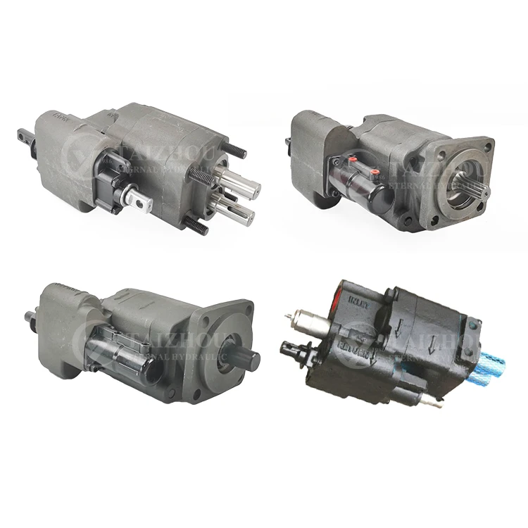
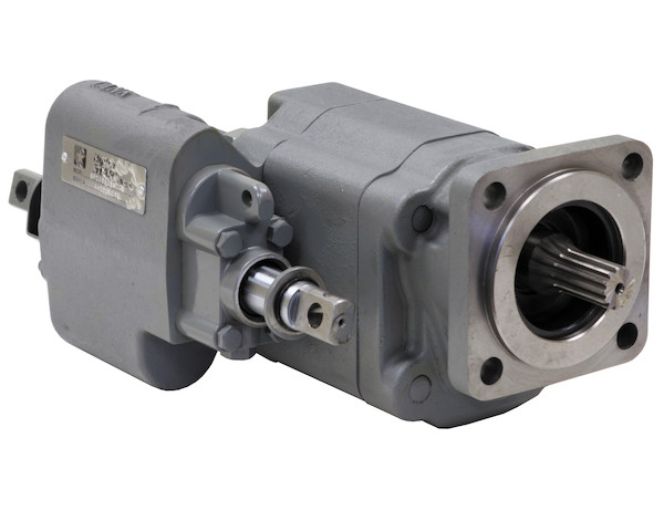
pto shaft driven hydraulic pump for dump truck free sample

551 pto hydraulic pump for dump truck products are offered for sale by suppliers on Alibaba.comAbout 28% % of these are hydraulic pumps, 7%% are other hydraulic parts, and 5%% are construction machinery parts.
A wide variety of pto hydraulic pump for dump truck options are available to you, You can also choose from piston pump, gear pump pto hydraulic pump for dump truck,as well as from 1 year, 6 months, and 1.5 years pto hydraulic pump for dump truck, and whether pto hydraulic pump for dump truck is hydraulic power units, fittings, or valves.

www.powermotiontech.com is using a security service for protection against online attacks. An action has triggered the service and blocked your request.
Please try again in a few minutes. If the issue persist, please contact the site owner for further assistance. Reference ID IP Address Date and Time 8bf2006c85a66667641f5dd58dcb3d35 63.210.148.230 03/11/2023 09:09 PM UTC
If you’ve spent any reasonable amount of time working on or around mobile machinery, you’re very familiar with PTO-driven machinery, including the hydraulic pump. The PTO shaft exiting the rear of a farm tractor is used to power mechanical implements through a drive shaft, such as bailers or mowers, themselves sometimes attached to the tractor itself via a 3-point hitch. Pumps are also mounted to the PTO shaft, providing an easy source of hydraulic energy in addition to the tractor’s secondary hydraulic outputs.
For on-road machineries, such as stone slingers, dump trucks or fire engines, no such external drive shaft is used. Instead, the transmission of the vehicle has a removable panel where a power take-off is mounted to provide a drive shaft or pad mount for pumps or other purposes. A hydraulic pump, for example, mounts either directly or closely to the PTO unit, supplying hydraulic energy for various machine functions.
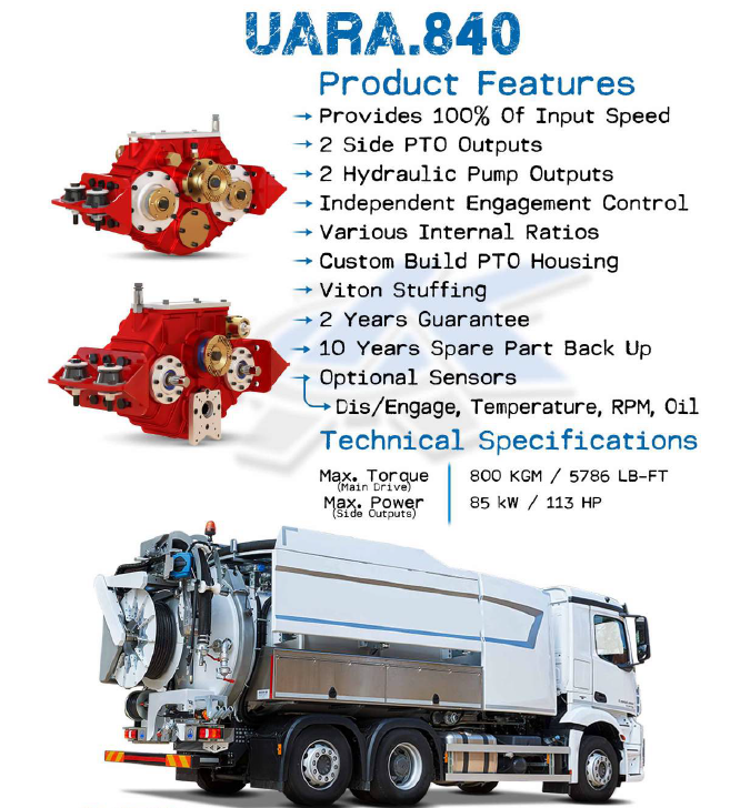
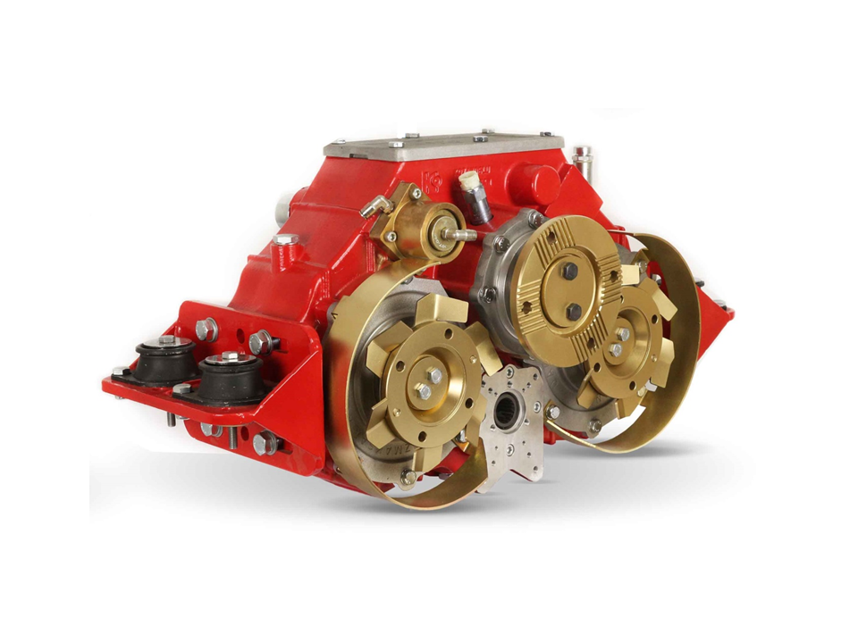
What both tractor and on-road PTO options require is a drive shaft terminating at the pump, eliminating any other purpose or potential for driving mechanical functions. Although options like a split shaft take-off or PTOs with multiple take-offs do exist, they’re expensive and bulky. As well, the location of the PTO drive is previously limited to under the truck or behind the tractor. A great new concept in the world of machine drives is the PTO through-drive motor.
A PTO through-drive motor allows the unique ability to mount the drive system anywhere your creativity conceives, so long as it’s run via a hydraulic pump elsewhere. Imagine mounting a drive shaft for a pond pump mounted at the end of an excavator’s arm? Or being able to mount a PTO driven implement to the back of your skid steer loader, powered by auxiliary hydraulics?
Linde offers such an animal, if you were doubting its existence, available as their HMV/R-02 series PTO motor. Essentially, it’ a through-drive motor with splined joints at either end allowing the attachment of various sizes of PTO shafts. Provided are two opposed shafts allowing it to fit in the driveline of existing equipment, so hydraulics can now power machinery previously only brought to life mechanically.
Just as with the standard HMV-02 series of motors from Linde, displacements are available all the way up to 331 cc/rev, and with up to 500 bar (7,250 psi), peak torque is well over 2,200 Nm (1,628 lb-ft), twisting with enough force to power most PTO driven machinery on the market. The Linde system works with five standard shaft sizes, each running ANSI B92.1 splined outputs.

Contact us with your PTO requirements. We can assist in choosing the proper PTO and offer competitive pricing. We can supply replacements for the following:
In addition, we offer a wide variety of hydraulic pumps and dump pumps (direct or remote mount applications), and PTO drive shaft kits. Call or e-mail with your requirements.
Also see the DRIVELINE, TRANSMISSION, TRANSFERCASE & PTO PARTS sub section under MILITARY VEHICLE PARTS for PTOs and pumps that are commonly used on military trucks.
����"The pump has a rotary valve to change between up and down. The valve is controlled from the tractor seat by rotating the lever on the blue shaft," he explains.
Pto-Powered Dump Trailer TRACTORS Power Take Offs PTO s When a friend offered him parts from a 1937 dump truck Steve Siter decided to use them to build a dump trailer ���� I was happy to give the truck s pto-powered hydraulic pump a new lease on life says Siter Paxton Mass ����A friend helped him weld a frame together out of channel iron and he built the 68 by 92 by 30-in bed out of new pressure treated lumber and rough sawn oak on the sideboards ����He had an adapter made to connect the pump to his tractor s pto shaft ���� The pump has a rotary valve to change between up and down The valve is controlled from the tractor seat by rotating the lever on the blue shaft he explains ����The dump works perfectly for moving brush cordwood and dirt ���� It s easy to use to back up and hitches up quick Siter says ����He estimates he spent about $300 for the tongue cylinder hardware and miscellaneous parts ����Contact: FARM SHOW Followup Steve Siter 488 Marshall St Paxton Mass 01612 ph 508 753-4870; k1wgn@yahoo com
Check that the electric motor is running. Although this is a simple concept, before you begin replacing parts, it’s critical that you make sure the electric motor is running. This can often be one of the easiest aspects to overlook, but it is necessary to confirm before moving forward.
Check that the pump shaft is rotating. Even though coupling guards and C-face mounts can make this difficult to confirm, it is important to establish if your pump shaft is rotating. If it isn’t, this could be an indication of a more severe issue, and this should be investigated immediately.
Check the oil level. This one tends to be the more obvious check, as it is often one of the only factors inspected before the pump is changed. The oil level should be three inches above the pump suction. Otherwise, a vortex can form in the reservoir, allowing air into the pump.
If the oil level is low, determine where the leak is in the system. Although this can be a difficult process, it is necessary to ensure your machines are performing properly. Leaks can be difficult to find.
What does the pump sound like when it is operating normally? Vane pumps generally are quieter than piston and gear pumps. If the pump has a high-pitched whining sound, it most likely is cavitating. If it has a knocking sound, like marbles rattling around, then aeration is the likely cause.
Cavitation is the formation and collapse of air cavities in the liquid. When the pump cannot get the total volume of oil it needs, cavitation occurs. Hydraulic oil contains approximately nine percent dissolved air. When the pump does not receive adequate oil volume at its suction port, high vacuum pressure occurs.
This dissolved air is pulled out of the oil on the suction side and then collapses or implodes on the pressure side. The implosions produce a very steady, high-pitched sound. As the air bubbles collapse, the inside of the pump is damaged.
While cavitation is a devastating development, with proper preventative maintenance practices and a quality monitoring system, early detection and deterrence remain attainable goals. UE System’s UltraTrak 850S CD pump cavitation sensor is a Smart Analog Sensor designed and optimized to detect cavitation on pumps earlier by measuring the ultrasound produced as cavitation starts to develop early-onset bubbles in the pump. By continuously monitoring the impact caused by cavitation, the system provides a simple, single value to trend and alert when cavitation is occurring.
The oil viscosity is too high. Low oil temperature increases the oil viscosity, making it harder for the oil to reach the pump. Most hydraulic systems should not be started with the oil any colder than 40°F and should not be put under load until the oil is at least 70°F.
Many reservoirs do not have heaters, particularly in the South. Even when heaters are available, they are often disconnected. While the damage may not be immediate, if a pump is continually started up when the oil is too cold, the pump will fail prematurely.
The suction filter or strainer is contaminated. A strainer is typically 74 or 149 microns in size and is used to keep “large” particles out of the pump. The strainer may be located inside or outside the reservoir. Strainers located inside the reservoir are out of sight and out of mind. Many times, maintenance personnel are not even aware that there is a strainer in the reservoir.
The suction strainer should be removed from the line or reservoir and cleaned a minimum of once a year. Years ago, a plant sought out help to troubleshoot a system that had already had five pumps changed within a single week. Upon closer inspection, it was discovered that the breather cap was missing, allowing dirty air to flow directly into the reservoir.
A check of the hydraulic schematic showed a strainer in the suction line inside the tank. When the strainer was removed, a shop rag was found wrapped around the screen mesh. Apparently, someone had used the rag to plug the breather cap opening, and it had then fallen into the tank. Contamination can come from a variety of different sources, so it pays to be vigilant and responsible with our practices and reliability measures.
The electric motor is driving the hydraulic pump at a speed that is higher than the pump’s rating. All pumps have a recommended maximum drive speed. If the speed is too high, a higher volume of oil will be needed at the suction port.
Due to the size of the suction port, adequate oil cannot fill the suction cavity in the pump, resulting in cavitation. Although this rarely happens, some pumps are rated at a maximum drive speed of 1,200 revolutions per minute (RPM), while others have a maximum speed of 3,600 RPM. The drive speed should be checked any time a pump is replaced with a different brand or model.
Every one of these devastating causes of cavitation threatens to cause major, irreversible damage to your equipment. Therefore, it’s not only critical to have proper, proactive practices in place, but also a monitoring system that can continuously protect your valuable assets, such as UE System’s UltraTrak 850S CD pump cavitation senor. These sensors regularly monitor the health of your pumps and alert you immediately if cavitation symptoms are present, allowing you to take corrective action before it’s too late.
Aeration is sometimes known as pseudo cavitation because air is entering the pump suction cavity. However, the causes of aeration are entirely different than that of cavitation. While cavitation pulls air out of the oil, aeration is the result of outside air entering the pump’s suction line.
Several factors can cause aeration, including an air leak in the suction line. This could be in the form of a loose connection, a cracked line, or an improper fitting seal. One method of finding the leak is to squirt oil around the suction line fittings. The fluid will be momentarily drawn into the suction line, and the knocking sound inside the pump will stop for a short period of time once the airflow path is found.
A bad shaft seal can also cause aeration if the system is supplied by one or more fixed displacement pumps. Oil that bypasses inside a fixed displacement pump is ported back to the suction port. If the shaft seal is worn or damaged, air can flow through the seal and into the pump’s suction cavity.
As mentioned previously, if the oil level is too low, oil can enter the suction line and flow into the pump. Therefore, always check the oil level with all cylinders in the retracted position.
If a new pump is installed and pressure will not build, the shaft may be rotating in the wrong direction. Some gear pumps can be rotated in either direction, but most have an arrow on the housing indicating the direction of rotation, as depicted in Figure 2.
Pump rotation should always be viewed from the shaft end. If the pump is rotated in the wrong direction, adequate fluid will not fill the suction port due to the pump’s internal design.
A fixed displacement pump delivers a constant volume of oil for a given shaft speed. A relief valve must be included downstream of the pump to limit the maximum pressure in the system.
After the visual and sound checks are made, the next step is to determine whether you have a volume or pressure problem. If the pressure will not build to the desired level, isolate the pump and relief valve from the system. This can be done by closing a valve, plugging the line downstream, or blocking the relief valve. If the pressure builds when this is done, there is a component downstream of the isolation point that is bypassing. If the pressure does not build up, the pump or relief valve is bad.
If the system is operating at a slower speed, a volume problem exists. Pumps wear over time, which results in less oil being delivered. While a flow meter can be installed in the pump’s outlet line, this is not always practical, as the proper fittings and adapters may not be available. To determine if the pump is badly worn and bypassing, first check the current to the electric motor. If possible, this test should be made when the pump is new to establish a reference. Electric motor horsepower is relative to the hydraulic horsepower required by the system.
For example, if a 50-GPM pump is used and the maximum pressure is 1,500 psi, a 50-hp motor will be required. If the pump is delivering less oil than when it was new, the current to drive the pump will drop. A 230-volt, 50-hp motor has an average full load rating of 130 amps. If the amperage is considerably lower, the pump is most likely bypassing and should be changed.
Figure 4.To isolate a fixed displacement pump and relief valve from the system, close a valve or plug the line downstream (left). If pressure builds, a component downstream of the isolation point is bypassing (right).
The most common type of variable displacement pump is the pressure-compensating design. The compensator setting limits the maximum pressure at the pump’s outlet port. The pump should be isolated as described for the fixed displacement pump.
If pressure does not build up, the relief valve or pump compensator may be bad. Prior to checking either component, perform the necessary lockout procedures and verify that the pressure at the outlet port is zero psi. The relief valve and compensator can then be taken apart and checked for contamination, wear, and broken springs.
Install a flow meter in the case drain line and check the flow rate. Most variable displacement pumps bypass one to three percent of the maximum pump volume through the case drain line. If the flow rate reaches 10 percent, the pump should be changed. Permanently installing a flow meter in the case drain line is an excellent reliability and troubleshooting tool.
Ensure the compensator is 200 psi above the maximum load pressure. If set too low, the compensator spool will shift and start reducing the pump volume when the system is calling for maximum volume.
Performing these recommended tests should help you make good decisions about the condition of your pumps or the cause of pump failures. If you change a pump, have a reason for changing it. Don’t just do it because you have a spare one in stock.
Conduct a reliability assessment on each of your hydraulic systems so when an issue occurs, you will have current pressure and temperature readings to consult.
Al Smiley is the president of GPM Hydraulic Consulting Inc., located in Monroe, Georgia. Since 1994, GPM has provided hydraulic training, consulting and reliability assessments to companies in t...

PTO (Power Take Off) is one of the functions for the active use of the truck. PTO is mainly mounted on work vehicles such as dump trucks and mixer trucks. A power source is required for the truck to perform operations such as tilting the loading platform and rotating the drum. PTO is a device that extract the power for that from the engine. Normally, the engine is a necessary part for running, but by using the power of the engine through the PTO, it is also possible to operate the truck body without any other power sources. There are some other trucks that have PTO system, such as aerial work vehicles including crane trucks or fire trucks, and tractors or garbage trucks which may be more familiar to you.
PTO (Power Take Off) generates power by changing engine rotation to “Hydraulic”. Hydraulic pressure is a mechanism that uses fluid called hydraulic fluid as an energy transmission medium. Hydraulic have the advantage of being able to move big thing with little power. It is also easy to operate because it can quickly move onto the operation once switched on, and also it is easy to adjust the force. Therefore, PTO is used on various work vehicles.
There are two types of PTO activation methods: switch type and lever type. Some types of PTOs that are activated by levers require clutch operations. Also, when PTO changes engine energy to hydraulic pressure, a part called “PTO shaft” is required. PTO shaft requires daily inspection and regular maintenances as they are subjected to be under heavy loads, and its deterioration can defect the PTO. Because the PTO shaft is heavy, please be careful not to hurt yourself during maintenance.

A dump truck, known also as a dumping truck, dump trailer, dumper trailer, dump lorry or dumper lorry or a dumper for short, is used for transporting materials (such as dirt, gravel, or demolition waste) for construction as well as coal. A typical dump truck is equipped with an open-box bed, which is hinged at the rear and equipped with hydraulic rams to lift the front, allowing the material in the bed to be deposited ("dumped") on the ground behind the truck at the site of delivery. In the UK, Australia, South Africa and India the term applies to off-road construction plants only and the road vehicle is known as a tip lorry, tipper lorry (UK, India), tipper truck, tip truck, tip trailer or tipper trailer or simply a tipper (Australia, New Zealand, South Africa).
The dump truck is thought to have been first conceived in the farms of late 19th century western Europe. Thornycroft developed a steam dust-cart in 1896 with a tipper mechanism.United States were developed by small equipment companies such as The Fruehauf Trailer Corporation, Galion Buggy Co. and Lauth-Juergens among many others around 1910.Hydraulic dump beds were introduced by Wood Hoist Co. shortly after. Such companies flourished during World War I due to massive wartime demand. August Fruehauf had obtained military contracts for his semi-trailer, invented in 1914 and later created the partner vehicle, the semi-truck for use in World War I. After the war, Fruehauf introduced hydraulics in his trailers. They offered hydraulic lift gates, hydraulic winches and a dump trailer for sales in the early 1920s. Fruehauf became the premier supplier of dump trailers and their famed "bathtub dump" was considered to be the best by heavy haulers, road and mining construction firms.
Companies like Galion Buggy Co. continued to grow after the war by manufacturing a number of express bodies and some smaller dump bodies that could be easily installed on either stock or converted (heavy-duty suspension and drivetrain) Model T chassis prior to 1920. Galion and Wood Mfg. Co. built all of the dump bodies offered by Ford on their heavy-duty AA and BB chassis during the 1930s.
The first known Canadian dump truck was developed in Saint John, New Brunswick, when Robert T. Mawhinney attached a dump box to a flatbed truck in 1920. The lifting device was a winch attached to a cable that fed over sheave (pulley) mounted on a mast behind the cab. The cable was connected to the lower front end of the wooden dump box which was attached by a pivot at the back of the truck frame. The operator turned a crank to raise and lower the box.
From the 1930s Euclid, International-Harvester and Mack contributed to ongoing development. Mack modified its existing trucks with varying success. In 1934 Euclid became the first manufacturer in the world to successfully produce a dedicated off-highway truck.
Today, virtually all dump trucks operate by hydraulics and they come in a variety of configurations each designed to accomplish a specific task in the construction material supply chain.
A standard dump truck is a truck chassis with a dump body mounted to the frame. The bed is raised by a vertical hydraulic ram mounted under the front of the body (known as a front post hoist configuration), or a horizontal hydraulic ram and lever arrangement between the frame rails (known as an underbody hoist configuration), and the back of the bed is hinged at the back of the truck. The tailgate (sometimes referred to as an end gate) can be configured to swing up on top hinges (and sometimes also to fold down on lower hinges)pneumatic or hydraulic rams lift the gate open and up above the dump body. Some bodies, typically for hauling grain, have swing-out doors for entering the box and a metering gate/chute in the center for a more controlled dumping.
In the United States most standard dump trucks have one front steering axle and one (4x24-wheeler)) or two (6x4 6-wheeler) rear axles which typically have dual wheels on each side. Tandem rear axles are almost always powered,
European Union heavy trucks often have two steering axles. Dump truck configurations are two, three, and four axles. The four-axle eight wheeler has two steering axles at the front and two powered axles at the rearmetric tons (35 short tons; 31 long tons) gross weight in most EU countries.
An Ashok Leyland Comet dump truck, an example of a very basic 4×2 dump truck used for payloads of 10 metric tons (11.0 short tons; 9.8 long tons) or less
A semi end dump is a tractor-trailer combination wherein the trailer itself contains the hydraulic hoist. In the US a typical semi end dump has a 3-axle tractor pulling a 2-axle trailer with dual tires, in the EU trailers often have 3 axles and single tires. The key advantage of a semi end dump is a large payload. A key disadvantage is that they are very unstable when raised in the dumping position limiting their use in many applications where the dumping location is uneven or off level.
The main difference between them is the different structure. The frame dump trailer has a large beam that runs along the bottom of the trailer to support it. The frameless dump trailer has no frame under the trailer but has ribs that go around the body for support and the top rail of the trailer serves as a suspension bridge for support.
The difference in structure also brings with it a difference in weight. Frame dump trailers are heavier. For the same length, a frame dump trailer weighs around 5 ton more than a frameless dump trailer.
Another configuration is called a triple transfer train, consisting of a "B" and "C" box. These are common on Nevada and Utah Highways, but not in California. Depending on the axle arrangement, a triple transfer can haul up to 129,000 kilograms (284,000 pounds) with a special permit in certain American states. As of 2007
Transfer dump trucks typically haul between 26 and 27 short tons (23.6 and 24.5 t; 23.2 and 24.1 long tons) of aggregate per load, each truck is capable of 3–5 loads per day, generally speaking.
A truck and pup is very similar to a transfer dump. It consists of a standard dump truck pulling a dump trailer. The pup trailer, unlike the transfer, has its own hydraulic ram and is capable of self-unloading.
A super dump is a straight dump truck equipped with a trailing axle, a liftable, load-bearing axle rated as high as 13,000 pounds (5,897 kg). Trailing 11 to 13 feet (3.35 to 3.96 m) behind the rear tandem, the trailing axle stretches the outer "bridge" measurement—the distance between the first and last axles—to the maximum overall length allowed. This increases the gross weight allowed under the federal bridge formula, which sets standards for truck size and weight. Depending on the vehicle length and axle configuration, Superdumps can be rated as high as 80,000 pounds (36,287 kg) GVW and carry 26 short tons (23.6 t; 23.2 long tons) of payload or more. When the truck is empty or ready to offload, the trailing axle toggles up off the road surface on two hydraulic arms to clear the rear of the vehicle. Truck owners call their trailing axle-equipped trucks Superdumps because they far exceed the payload, productivity, and return on investment of a conventional dump truck. The Superdump and trailing axle concept were developed by Strong Industries of Houston, Texas.
A semi bottom dump, bottom hopper, or belly dump is a (commonly) 3-axle tractor pulling a 2-axle trailer with a clam shell type dump gate in the belly of the trailer. The key advantage of a semi bottom dump is its ability to lay material in a windrow, a linear heap. In addition, a semi bottom dump is maneuverable in reverse, unlike the double and triple trailer configurations described below. These trailers may be found either of the windrow type shown in the photo or may be of the cross spread type, with the gate opening front to rear instead of left and right. The cross spread type gate will actually spread the cereal grains fairly and evenly from the width of the trailer. By comparison, the windrow-type gate leaves a pile in the middle. The cross spread type gate, on the other hand, tends to jam and may not work very well with coarse materials.
Double and triple bottom dumps consist of a 2-axle tractor pulling one single-axle semi-trailer and an additional full trailer (or two full trailers in the case of triples). These dump trucks allow the driver to lay material in windrows without leaving the cab or stopping the truck. The main disadvantage is the difficulty in backing double and triple units.
The specific type of dump truck used in any specific country is likely to be closely keyed to the weight and axle limitations of that jurisdiction. Rock, dirt, and other types of materials commonly hauled in trucks of this type are quite heavy, and almost any style of truck can be easily overloaded. Because of that, this type of truck is frequently configured to take advantage of local weight limitations to maximize the cargo. For example, within the United States, the maximum weight limit is 40 short tons (36.3 t; 35.7 long tons) throughout the country, except for specific bridges with lower limits. Individual states, in some instances, are allowed to authorize trucks up to 52.5 short tons (47.6 t; 46.9 long tons). Most states that do so require that the trucks be very long, to spread the weight over more distance. It is in this context that double and triple bottoms are found within the United States.
Dump trailers come with a range of options and features such as tarp kits, high side options, dump/spread/swing gates, remote control, scissor, telescop, dual or single cylinder lifts, and metal locking toolboxes. They offer the perfect solution for a variety of applications, including roofing, rock and mulch delivery, general contractors, skid steer grading, trash out, and recycling.
A side dump truck (SDT) consists of a 3-axle tractor pulling a 2-axle semi-trailer. It has hydraulic rams that tilt the dump body onto its side, spilling the material to either the left or right side of the trailer. The key advantages of the side dump are that it allows rapid unloading and can carry more weight in the western United States. In addition, it is almost immune to upset (tipping over) while dumping, unlike the semi end dumps which are very prone to tipping over. It is, however, highly likely that a side dump trailer will tip over if dumping is stopped prematurely. Also, when dumping loose materials or cobble sized stone, the side dump can become stuck if the pile becomes wide enough to cover too much of the trailer"s wheels. Trailers that dump at the appropriate angle (50° for example) avoid the problem of the dumped load fouling the path of the trailer wheels by dumping their loads further to the side of the truck, in some cases leaving sufficient clearance to walk between the dumped load and the trailer.
Many ballast to weigh the truck down or to hold sodium or calcium chloride salts for spreading on snow and ice-covered surfaces. Plowing is severe service and needs heavy-duty trucks.
A hook-lift system ("roller container" in the UK) does the same job, but lifts, lowers, and dumps the container with a boom arrangement instead of a cable and hoist.
Off-highway dump trucksheavy construction equipment and share little resemblance to highway dump trucks. Bigger off-highway dump trucks are used strictly off-road for mining and heavy dirt hauling jobs. There are two primary forms: rigid frame and articulating frame.
The term "dump" truck is not generally used by the mining industry, or by the manufacturers that build these machines. The more appropriate U.S. term for this strictly off-road vehicle is "haul truck" and the equivalent European term is "dumper".
Haul trucks are used in large surface mines and quarries. They have a rigid frame and conventional steering with drive at the rear wheel. As of late 2013, the largest ever production haul truck is the 450 metric ton BelAZ 75710, followed by the Liebherr T 282B, the Bucyrus MT6300AC and the Caterpillar 797F, which each have payload capacities of up to 400 short tons (363 t; 357 long tons). Most large-size haul trucks employ Diesel-electric powertrains, using the Diesel engine to drive an AC alternator or DC generator that sends electric power to electric motors at each rear wheel. The Caterpillar 797 is unique for its size, as it employs a Diesel engine to power a mechanical powertrain, typical of most road-going vehicles and intermediary size haul trucks.
An articulated dumper is an all-wheel-drive, off-road dump truck. It has a hinge between the cab and the dump box but is distinct from a semi-trailer truck in that the power unit is a permanent fixture, not a separable vehicle. Steering is accomplished via hydraulic cylinders that pivot the entire tractor in relation to the trailer, rather than rack and pinion steering on the front axle as in a conventional dump truck. By this way of steering, the trailer"s wheels follow the same path as the front wheels. Together with all-wheel drive and low center of gravity, it is highly adaptable to rough terrain. Major manufacturers include Volvo CE, Terex, John Deere, and Caterpillar.
U-shaped dump trucks, also known as tub-body trucks, is used to transport construction waste, it is made of high-strength super wear-resistant special steel plate directly bent, and has the characteristics of impact resistance, alternating stress resistance, corrosion resistance and so on.
U-shaped dump truck, there is no dead angle at the corners of the cargo box, it is not easy to stick to the box when unloading, and the unloading is cleaner.
The U-shaped cargo box reduces its own weight through structural optimization. Now the most common U-shaped dump is to use high-strength plates. Under the premise of ensuring the strength of the car body, the thickness of the plate is reduced by about 20%, and the self-weight of the car is reduced by about 1 ton, which effectively improves the utilization factor of the load mass.
3. Strong carrying capacity.Using high-strength steel plate, high yield strength, better impact resistance and fatigue resistance. For users of ore transportation, it can reduce the damage of ore to the container.
Dump trucks are normally built for some amount of off-road or construction site driving; as the driver is protected by the chassis and height of the driver"s seat, bumpers are either placed high or omitted for added ground clearance. The disadvantage is that in a collision with a standard car, the entire motor section or luggage compartment goes under the truck. Thus, the passengers in the car could be more severely injured than would be common in a collision with another car. Several countries have made rules that new trucks should have bumpers approximately 40 cm (16 in) above ground in order to protect other drivers. There are also rules about how long the load or construction of the truck can go beyond the rear bumper to prevent cars that rear-end the truck from going under it.
Another safety consideration is the leveling of the truck before unloading. If the truck is not parked on relatively horizontal ground, the sudden change of weight and balance due to lifting of the body and dumping of the material can cause the truck to slide, or even to tip over.live bottom trailer is an approach to eliminate this danger.
Because of their size and the difficulty of maintaining visual contact with on-foot workers, dump trucks can be a threat, especially when backing up.back-up alarms provide some level of protection, and having a spotter working with the driver also decreases back-up injuries and fatalities.
"The Super Haul Truck" (PDF). Britannia Mine Museum. BC Museum of Mining Education Services. Archived from the original (PDF) on 2012-03-11. Retrieved 2017-12-20.
"Owners Manual Dump Trailers" (PDF). Mac Trailers. 2010. pp. 22–26. Archived from the original (PDF) on 23 September 2016. Retrieved 21 September 2016.
www.fleetmaintenance.com is using a security service for protection against online attacks. An action has triggered the service and blocked your request.
Please try again in a few minutes. If the issue persist, please contact the site owner for further assistance. Reference ID IP Address Date and Time 2f7ccbe0932db008d7959d5f0442459d 63.210.148.230 03/11/2023 09:09 PM UTC
When a hydraulic system fails, finding the source of the problem can be a challenge. Though hydraulic systems primarily consist of a sump, motor, pump, valves, actuators and hydraulic fluid, any of these parts could be the source of failure. That"s not to mention the additional potential for failure through human error and faulty maintenance practices. If your system fails, you need to know why it fails, how to find the failure and how to keep it running smoothly in the future, all while keeping personnel safe.
It"s often easy to tell when a hydraulic system fails — symptoms can include high temperatures, low pressure readings and slow or erratic operation are glaring problems. But what are the most common causes of hydraulic systems failures? We can trace most hydraulic issues back to a few common causes, listed below.
Air and water contamination are the leading causes of hydraulic failure, accounting for 80 to 90% of hydraulic failures. Faulty pumps, system breaches or temperature issues often cause both types of contamination.
Air contamination is the entrance of air into a hydraulic system and consists of two types — aeration and cavitation. Both can cause severe damage to the hydraulic system over time by wearing down the pump and surrounding components, contaminating hydraulic fluids and even overheating the system. Although we are not pump manufacturers, we know it is essential to be aware of these types of contamination and how to identify their symptoms.
Cavitation:Hydraulic oil consists of about 9% dissolved air, which the pump can pull out and implode, causing pump problems and damage to the pump and to other components in a hydraulic system over time. You can identify this problem if your hydraulic pump is making a whining noise.
Aeration:Aeration occurs when air enters the pump cavity from an outside source. Usually, loose connections or leaks in the system cause this issue. Aeration also creates a sound when the pump is running, which sounds like knocking.
Water contamination is also a common problem in hydraulic systems, often caused by system leaks or condensation due to temperature changes. Water can degrade hydraulic components over time through oxidation and freeze damage. A milky appearance in hydraulic fluid can help you identify water contamination.
Fluid oxidization: Extreme heat can cause hydraulic fluid to oxidize and thicken. This fluid thickening can cause buildups in the system that restrict flow, but can also further reduce the ability of the system to dissipate heat.
Fluid thickening:Low temperatures increase the viscosity of hydraulic oil, making it harder for the oil to reach the pump. Putting systems under load before the oil reaches 70 degrees or more can damage the system through cavitation.
Fluid levels and quality can affect hydraulic system performance. Low fluid levels and inappropriate filtration can result in air contamination, while fluid contamination can cause temperature problems. Leaks can further exacerbate both issues.
Using the correct type of fluid is also essential, as certain hydraulic oils are compatible with specific applications. There are even oil options that offer higher resistance to temperature-related problems. Some oils even offer anti-wear and anti-foam additives to help prevent against wear and air contamination, respectively.
Human error is the base cause of many hydraulic system problems. Some of the most common errors that may result in your hydraulic pump not building pressure include the following.
Faulty installations: Improper installation of any component in a hydraulic system can result in severe errors. For example, the pump shaft may be rotating in the wrong direction, negatively affecting pressure buildup, or pipes may be incorrectly fitted, resulting in leaks.
Incompatible parts: An inexperienced installer may put mismatched components together, resulting in functional failures. For example, a pump may have a motor that runs beyond its maximum drive speed.
Improper maintenance or usage:Using systems outside their operational capabilities or failing to perform regular maintenance are some of the most common causes of hydraulic system damage, but are easy to rectify through updated maintenance policies and training.
The sources of system failures can be tricky to identify, but some hydraulic troubleshooting steps can help narrow down the options. So how do you troubleshoot a hydraulic system? Here are some of the fundamentals.
Check the pump: Take the pump assembly apart and assess all parts to ensure that they are functional and installed correctly. The most common problem areas include the pump shaft, coupling and filter.
Check the fluids:Check the level, color and viscosity of the hydraulic oil to ensure it meets specifications and has not become contaminated. Low hydraulic fluid symptoms include pressure or power loss. When in doubt, drain and replace the fluids.
Check the seals: Look for evidence of any fluid leakage around your hydraulic system"s seals, especially the shaft seal. Leakage can indicate worn-out or blown seals that can cause malfunctions with pumps, motors and control valves.
Check the filters: Ensure filters are clear of plugs and blockages. Common clogged hydraulic filter symptoms include sluggish operation and noisy operation.
Check valves and lines: Observe all lines for potential leaks, and tighten every connection point. Also, check the relief valve for any signs of damage.
Run the system: When you have completed all these essential checks, turn on the system and monitor it for pressure and temperature fluctuations, as well as abnormal sounds. If all seems well, check your pressure sensor for potential failure.
Hydraulic system issues are inevitable at some point. However, simple steps can help you avoid these issues and increase the longevity of your hydraulic system. On top of effective troubleshooting, you can prevent hydraulic system failure by taking the following steps.
Follow specifications: We can trace the most common hydraulic system issues back to fundamental system problems like incompatible or improperly installed parts. For this reason, it"s essential to always double-check specifications to ensure your purchased parts can work together seamlessly.
Consult with professionals: When purchasing new equipment, consult with industry peers and professionals to discover what they recommend. While manufacturers can tell you how a product should work, industry professionals can provide concrete examples of how well the equipment works for their industry.
Perform maintenance: It is essential to focus your operations on equipment longevity. Review your daily, monthly and annual maintenance procedures to ensure you are covering every aspect of your system according to best maintenance practices and catch symptoms early on.
On top of these steps, look into hydraulic system products that are specifically designed to help prevent failures. One such product is Bear-Loc® by York Precision. This innovative locking actuator is a safe, reliable feature for hydraulic components, automatically locking when sleeve pressure is relieved, preventing movement if a hydraulic system fails. This way, your can protect your personnel from injuries related to hydraulic failures. Even better, York Precision offers in-house design, engineering expertise and machining and manufacturing capabilities to produce a hydraulic locking device that meets your exact specifications.
Regularly review hydraulic system maintenance, always following manufacturer recommendations and industry best practices. Also, consider the storage condition, external influences, working pressure and usage frequency of your system to tailor your maintenance schedule and procedures.
Daily tasks:Take care of a few simple daily checks to avoid issues. For example, personnel should check the oil levels, hoses and connections and listen to the pump for abnormal sounds.
Routine tasks:Plan and execute a weekly and monthly maintenance routine, checking for the most common failure sources given your system"s working conditions. These should include components, filters and the condition of the oil.
Complete system checks: Depending on the conditions of your system, you and your team should perform complete systems checks monthly, quarterly or annually. Tasks should include running a comprehensive report on the system, cleaning devices, draining the system and replacing damaged parts.
Be mindful of location:Do not stand at endpoints while working on hydraulic systems. This safety measure can help prevent loss of limb and life, as there is a lot of pressure built up in these areas that can release and result in life-threatening situations.
Use caution around running systems:Always keep an eye out on pressure taps, couplings and hoses when they are under pressure. If something does not look right, power down the system before checking it. Loose or faulty parts can easily become deadly projectiles.
The best safety measures, however, are to perform excellent maintenance and use high-quality parts. If you"re looking for a quality hydraulic component manufacturer, York Precision Machining & Hydraulics can help.


 8613371530291