
purpose of a hydraulic pump factory

Hydraulic pumps are mechanisms in hydraulic systems that move hydraulic fluid from point to point initiating the production of hydraulic power. Hydraulic pumps are sometimes incorrectly referred to as “hydrolic” pumps.
They are an important device overall in the hydraulics field, a special kind of power transmission which controls the energy which moving fluids transmit while under pressure and change into mechanical energy. Other kinds of pumps utilized to transmit hydraulic fluids could also be referred to as hydraulic pumps. There is a wide range of contexts in which hydraulic systems are applied, hence they are very important in many commercial, industrial, and consumer utilities.
“Power transmission” alludes to the complete procedure of technologically changing energy into a beneficial form for practical applications. Mechanical power, electrical power, and fluid power are the three major branches that make up the power transmission field. Fluid power covers the usage of moving gas and moving fluids for the transmission of power. Hydraulics are then considered as a sub category of fluid power that focuses on fluid use in opposition to gas use. The other fluid power field is known as pneumatics and it’s focused on the storage and release of energy with compressed gas.
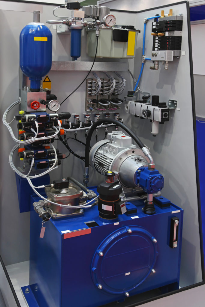
"Pascal"s Law" applies to confined liquids. Thus, in order for liquids to act hydraulically, they must be contained within a system. A hydraulic power pack or hydraulic power unit is a confined mechanical system that utilizes liquid hydraulically. Despite the fact that specific operating systems vary, all hydraulic power units share the same basic components. A reservoir, valves, a piping/tubing system, a pump, and actuators are examples of these components. Similarly, despite their versatility and adaptability, these mechanisms work together in related operating processes at the heart of all hydraulic power packs.
The hydraulic reservoir"s function is to hold a volume of liquid, transfer heat from the system, permit solid pollutants to settle, and aid in releasing moisture and air from the liquid.
Mechanical energy is changed to hydraulic energy by the hydraulic pump. This is accomplished through the movement of liquid, which serves as the transmission medium. All hydraulic pumps operate on the same basic principle of dispensing fluid volume against a resistive load or pressure.
Hydraulic valves are utilized to start, stop, and direct liquid flow in a system. Hydraulic valves are made of spools or poppets and can be actuated hydraulically, pneumatically, manually, electrically, or mechanically.
The end result of Pascal"s law is hydraulic actuators. This is the point at which hydraulic energy is transformed back to mechanical energy. This can be accomplished by using a hydraulic cylinder to transform hydraulic energy into linear movement and work or a hydraulic motor to transform hydraulic energy into rotational motion and work. Hydraulic motors and hydraulic cylinders, like hydraulic pumps, have various subtypes, each meant for specific design use.
The essence of hydraulics can be found in a fundamental physical fact: fluids are incompressible. (As a result, fluids more closely resemble solids than compressible gasses) The incompressible essence of fluid allows it to transfer force and speed very efficiently. This fact is summed up by a variant of "Pascal"s Principle," which states that virtually all pressure enforced on any part of a fluid is transferred to every other part of the fluid. This scientific principle states, in other words, that pressure applied to a fluid transmits equally in all directions.
Furthermore, the force transferred through a fluid has the ability to multiply as it moves. In a slightly more abstract sense, because fluids are incompressible, pressurized fluids should keep a consistent pressure just as they move. Pressure is defined mathematically as a force acting per particular area unit (P = F/A). A simplified version of this equation shows that force is the product of area and pressure (F = P x A). Thus, by varying the size or area of various parts inside a hydraulic system, the force acting inside the pump can be adjusted accordingly (to either greater or lesser). The need for pressure to remain constant is what causes force and area to mirror each other (on the basis of either shrinking or growing). A hydraulic system with a piston five times larger than a second piston can demonstrate this force-area relationship. When a force (e.g., 50lbs) is exerted on the smaller piston, it is multiplied by five (e.g., 250 lbs) and transmitted to the larger piston via the hydraulic system.
Hydraulics is built on fluids’ chemical properties and the physical relationship between pressure, area, and force. Overall, hydraulic applications allow human operators to generate and exert immense mechanical force with little to no physical effort. Within hydraulic systems, both oil and water are used to transmit power. The use of oil, on the other hand, is far more common, owing in part to its extremely incompressible nature.
Pressure relief valves prevent excess pressure by regulating the actuators’ output and redirecting liquid back to the reservoir when necessary. Directional control valves are used to change the size and direction of hydraulic fluid flow.
While hydraulic power transmission is remarkably useful in a wide range of professional applications, relying solely on one type of power transmission is generally unwise. On the contrary, the most efficient strategy is to combine a wide range of power transmissions (pneumatic, hydraulic, mechanical, and electrical). As a result, hydraulic systems must be carefully embedded into an overall power transmission strategy for the specific commercial application. It is necessary to invest in locating trustworthy and skilled hydraulic manufacturers/suppliers who can aid in the development and implementation of an overall hydraulic strategy.
The intended use of a hydraulic pump must be considered when selecting a specific type. This is significant because some pumps may only perform one function, whereas others allow for greater flexibility.
The pump"s material composition must also be considered in the application context. The cylinders, pistons, and gears are frequently made of long-lasting materials like aluminum, stainless steel, or steel that can withstand the continuous wear of repeated pumping. The materials must be able to withstand not only the process but also the hydraulic fluids. Composite fluids frequently contain oils, polyalkylene glycols, esters, butanol, and corrosion inhibitors (though water is used in some instances). The operating temperature, flash point, and viscosity of these fluids differ.
In addition to material, manufacturers must compare hydraulic pump operating specifications to make sure that intended utilization does not exceed pump abilities. The many variables in hydraulic pump functionality include maximum operating pressure, continuous operating pressure, horsepower, operating speed, power source, pump weight, and maximum fluid flow. Standard measurements like length, rod extension, and diameter should be compared as well. Because hydraulic pumps are used in lifts, cranes, motors, and other heavy machinery, they must meet strict operating specifications.
It is critical to recall that the overall power generated by any hydraulic drive system is influenced by various inefficiencies that must be considered in order to get the most out of the system. The presence of air bubbles within a hydraulic drive, for example, is known for changing the direction of the energy flow inside the system (since energy is wasted on the way to the actuators on bubble compression). Using a hydraulic drive system requires identifying shortfalls and selecting the best parts to mitigate their effects. A hydraulic pump is the "generator" side of a hydraulic system that initiates the hydraulic procedure (as opposed to the "actuator" side that completes the hydraulic procedure). Regardless of disparities, all hydraulic pumps are responsible for displacing liquid volume and transporting it to the actuator(s) from the reservoir via the tubing system. Some form of internal combustion system typically powers pumps.
While the operation of hydraulic pumps is normally the same, these mechanisms can be split into basic categories. There are two types of hydraulic pumps to consider: gear pumps and piston pumps. Radial and axial piston pumps are types of piston pumps. Axial pumps produce linear motion, whereas radial pumps can produce rotary motion. The gear pump category is further subdivided into external gear pumps and internal gear pumps.
Each type of hydraulic pump, regardless of piston or gear, is either double-action or single-action. Single-action pumps can only pull, push, or lift in one direction, while double-action pumps can pull, push, or lift in multiple directions.
Vane pumps are positive displacement pumps that maintain a constant flow rate under varying pressures. It is a pump that self-primes. It is referred to as a "vane pump" because the effect of the vane pressurizes the liquid.
This pump has a variable number of vanes mounted onto a rotor that rotates within the cavity. These vanes may be variable in length and tensioned to maintain contact with the wall while the pump draws power. The pump also features a pressure relief valve, which prevents pressure rise inside the pump from damaging it.
Internal gear pumps and external gear pumps are the two main types of hydraulic gear pumps. Pumps with external gears have two spur gears, the spurs of which are all externally arranged. Internal gear pumps also feature two spur gears, and the spurs of both gears are internally arranged, with one gear spinning around inside the other.
Both types of gear pumps deliver a consistent amount of liquid with each spinning of the gears. Hydraulic gear pumps are popular due to their versatility, effectiveness, and fairly simple design. Furthermore, because they are obtainable in a variety of configurations, they can be used in a wide range of consumer, industrial, and commercial product contexts.
Hydraulic ram pumps are cyclic machines that use water power, also referred to as hydropower, to transport water to a higher level than its original source. This hydraulic pump type is powered solely by the momentum of moving or falling water.
Ram pumps are a common type of hydraulic pump, especially among other types of hydraulic water pumps. Hydraulic ram pumps are utilized to move the water in the waste management, agricultural, sewage, plumbing, manufacturing, and engineering industries, though only about ten percent of the water utilized to run the pump gets to the planned end point.
Despite this disadvantage, using hydropower instead of an external energy source to power this kind of pump makes it a prominent choice in developing countries where the availability of the fuel and electricity required to energize motorized pumps is limited. The use of hydropower also reduces energy consumption for industrial factories and plants significantly. Having only two moving parts is another advantage of the hydraulic ram, making installation fairly simple in areas with free falling or flowing water. The water amount and the rate at which it falls have an important effect on the pump"s success. It is critical to keep this in mind when choosing a location for a pump and a water source. Length, size, diameter, minimum and maximum flow rates, and speed of operation are all important factors to consider.
Hydraulic water pumps are machines that move water from one location to another. Because water pumps are used in so many different applications, there are numerous hydraulic water pump variations.
Water pumps are useful in a variety of situations. Hydraulic pumps can be used to direct water where it is needed in industry, where water is often an ingredient in an industrial process or product. Water pumps are essential in supplying water to people in homes, particularly in rural residences that are not linked to a large sewage circuit. Water pumps are required in commercial settings to transport water to the upper floors of high rise buildings. Hydraulic water pumps in all of these situations could be powered by fuel, electricity, or even by hand, as is the situation with hydraulic hand pumps.
Water pumps in developed economies are typically automated and powered by electricity. Alternative pumping tools are frequently used in developing economies where dependable and cost effective sources of electricity and fuel are scarce. Hydraulic ram pumps, for example, can deliver water to remote locations without the use of electricity or fuel. These pumps rely solely on a moving stream of water’s force and a properly configured number of valves, tubes, and compression chambers.
Electric hydraulic pumps are hydraulic liquid transmission machines that use electricity to operate. They are frequently used to transfer hydraulic liquid from a reservoir to an actuator, like a hydraulic cylinder. These actuation mechanisms are an essential component of a wide range of hydraulic machinery.
There are several different types of hydraulic pumps, but the defining feature of each type is the use of pressurized fluids to accomplish a job. The natural characteristics of water, for example, are harnessed in the particular instance of hydraulic water pumps to transport water from one location to another. Hydraulic gear pumps and hydraulic piston pumps work in the same way to help actuate the motion of a piston in a mechanical system.
Despite the fact that there are numerous varieties of each of these pump mechanisms, all of them are powered by electricity. In such instances, an electric current flows through the motor, which turns impellers or other devices inside the pump system to create pressure differences; these differential pressure levels enable fluids to flow through the pump. Pump systems of this type can be utilized to direct hydraulic liquid to industrial machines such as commercial equipment like elevators or excavators.
Hydraulic hand pumps are fluid transmission machines that utilize the mechanical force generated by a manually operated actuator. A manually operated actuator could be a lever, a toggle, a handle, or any of a variety of other parts. Hydraulic hand pumps are utilized for hydraulic fluid distribution, water pumping, and various other applications.
Hydraulic hand pumps may be utilized for a variety of tasks, including hydraulic liquid direction to circuits in helicopters and other aircraft, instrument calibration, and piston actuation in hydraulic cylinders. Hydraulic hand pumps of this type use manual power to put hydraulic fluids under pressure. They can be utilized to test the pressure in a variety of devices such as hoses, pipes, valves, sprinklers, and heat exchangers systems. Hand pumps are extraordinarily simple to use.
Each hydraulic hand pump has a lever or other actuation handle linked to the pump that, when pulled and pushed, causes the hydraulic liquid in the pump"s system to be depressurized or pressurized. This action, in the instance of a hydraulic machine, provides power to the devices to which the pump is attached. The actuation of a water pump causes the liquid to be pulled from its source and transferred to another location. Hydraulic hand pumps will remain relevant as long as hydraulics are used in the commerce industry, owing to their simplicity and easy usage.
12V hydraulic pumps are hydraulic power devices that operate on 12 volts DC supplied by a battery or motor. These are specially designed processes that, like all hydraulic pumps, are applied in commercial, industrial, and consumer places to convert kinetic energy into beneficial mechanical energy through pressurized viscous liquids. This converted energy is put to use in a variety of industries.
Hydraulic pumps are commonly used to pull, push, and lift heavy loads in motorized and vehicle machines. Hydraulic water pumps may also be powered by 12V batteries and are used to move water out of or into the desired location. These electric hydraulic pumps are common since they run on small batteries, allowing for ease of portability. Such portability is sometimes required in waste removal systems and vehiclies. In addition to portable and compact models, options include variable amp hour productions, rechargeable battery pumps, and variable weights.
While non rechargeable alkaline 12V hydraulic pumps are used, rechargeable ones are much more common because they enable a continuous flow. More considerations include minimum discharge flow, maximum discharge pressure, discharge size, and inlet size. As 12V batteries are able to pump up to 150 feet from the ground, it is imperative to choose the right pump for a given use.
Air hydraulic pumps are hydraulic power devices that use compressed air to stimulate a pump mechanism, generating useful energy from a pressurized liquid. These devices are also known as pneumatic hydraulic pumps and are applied in a variety of industries to assist in the lifting of heavy loads and transportation of materials with minimal initial force.
Air pumps, like all hydraulic pumps, begin with the same components. The hydraulic liquids, which are typically oil or water-based composites, require the use of a reservoir. The fluid is moved from the storage tank to the hydraulic cylinder via hoses or tubes connected to this reservoir. The hydraulic cylinder houses a piston system and two valves. A hydraulic fluid intake valve allows hydraulic liquid to enter and then traps it by closing. The discharge valve is the point at which the high pressure fluid stream is released. Air hydraulic pumps have a linked air cylinder in addition to the hydraulic cylinder enclosing one end of the piston.
The protruding end of the piston is acted upon by a compressed air compressor or air in the cylinder. When the air cylinder is empty, a spring system in the hydraulic cylinder pushes the piston out. This makes a vacuum, which sucks fluid from the reservoir into the hydraulic cylinder. When the air compressor is under pressure, it engages the piston and pushes it deeper into the hydraulic cylinder and compresses the liquids. This pumping action is repeated until the hydraulic cylinder pressure is high enough to forcibly push fluid out through the discharge check valve. In some instances, this is connected to a nozzle and hoses, with the important part being the pressurized stream. Other uses apply the energy of this stream to pull, lift, and push heavy loads.
Hydraulic piston pumps transfer hydraulic liquids through a cylinder using plunger-like equipment to successfully raise the pressure for a machine, enabling it to pull, lift, and push heavy loads. This type of hydraulic pump is the power source for heavy-duty machines like excavators, backhoes, loaders, diggers, and cranes. Piston pumps are used in a variety of industries, including automotive, aeronautics, power generation, military, marine, and manufacturing, to mention a few.
Hydraulic piston pumps are common due to their capability to enhance energy usage productivity. A hydraulic hand pump energized by a hand or foot pedal can convert a force of 4.5 pounds into a load-moving force of 100 pounds. Electric hydraulic pumps can attain pressure reaching 4,000 PSI. Because capacities vary so much, the desired usage pump must be carefully considered. Several other factors must also be considered. Standard and custom configurations of operating speeds, task-specific power sources, pump weights, and maximum fluid flows are widely available. Measurements such as rod extension length, diameter, width, and height should also be considered, particularly when a hydraulic piston pump is to be installed in place of a current hydraulic piston pump.
Hydraulic clutch pumps are mechanisms that include a clutch assembly and a pump that enables the user to apply the necessary pressure to disengage or engage the clutch mechanism. Hydraulic clutches are crafted to either link two shafts and lock them together to rotate at the same speed or detach the shafts and allow them to rotate at different speeds as needed to decelerate or shift gears.
Hydraulic pumps change hydraulic energy to mechanical energy. Hydraulic pumps are particularly designed machines utilized in commercial, industrial, and residential areas to generate useful energy from different viscous liquids pressurization. Hydraulic pumps are exceptionally simple yet effective machines for moving fluids. "Hydraulic" is actually often misspelled as "Hydralic". Hydraulic pumps depend on the energy provided by hydraulic cylinders to power different machines and mechanisms.
There are several different types of hydraulic pumps, and all hydraulic pumps can be split into two primary categories. The first category includes hydraulic pumps that function without the assistance of auxiliary power sources such as electric motors and gas. These hydraulic pump types can use the kinetic energy of a fluid to transfer it from one location to another. These pumps are commonly called ram pumps. Hydraulic hand pumps are never regarded as ram pumps, despite the fact that their operating principles are similar.
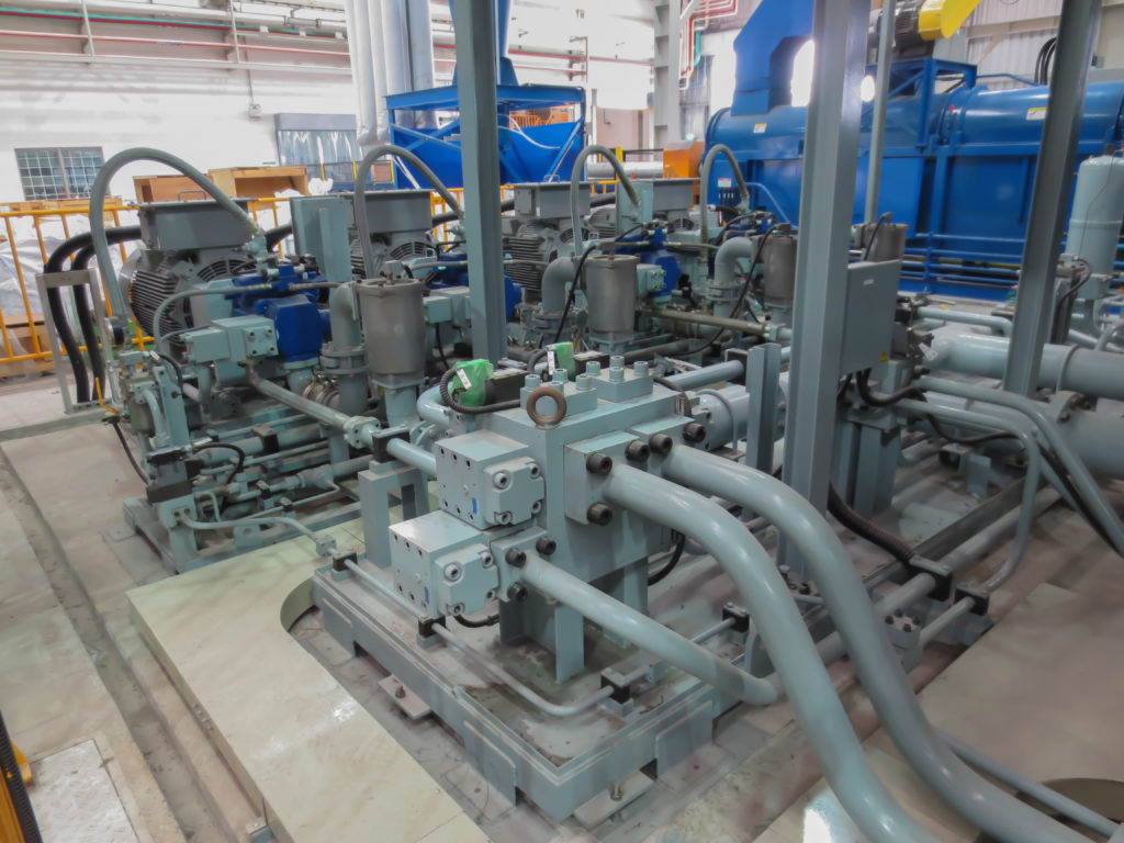
The construction, excavation, automotive manufacturing, agriculture, manufacturing, and defense contracting industries are just a few examples of operations that apply hydraulics power in normal, daily procedures. Since hydraulics usage is so prevalent, hydraulic pumps are unsurprisingly used in a wide range of machines and industries. Pumps serve the same basic function in all contexts where hydraulic machinery is used: they transport hydraulic fluid from one location to another in order to generate hydraulic energy and pressure (together with the actuators).
Elevators, automotive brakes, automotive lifts, cranes, airplane flaps, shock absorbers, log splitters, motorboat steering systems, garage jacks and other products use hydraulic pumps. The most common application of hydraulic pumps in construction sites is in big hydraulic machines and different types of "off-highway" equipment such as excavators, dumpers, diggers, and so on. Hydraulic systems are used in other settings, such as offshore work areas and factories, to power heavy machinery, cut and bend material, move heavy equipment, and so on.
Fluid’s incompressible nature in hydraulic systems allows an operator to make and apply mechanical power in an effective and efficient way. Practically all force created in a hydraulic system is applied to the intended target.
Because of the relationship between area, pressure, and force (F = P x A), modifying the force of a hydraulic system is as simple as changing the size of its components.
Hydraulic systems can transfer energy on an equal level with many mechanical and electrical systems while being significantly simpler in general. A hydraulic system, for example, can easily generate linear motion. On the contrary, most electrical and mechanical power systems need an intermediate mechanical step to convert rotational motion to linear motion.
Hydraulic systems are typically smaller than their mechanical and electrical counterparts while producing equivalents amounts of power, providing the benefit of saving physical space.
Hydraulic systems can be used in a wide range of physical settings due to their basic design (a pump attached to actuators via some kind of piping system). Hydraulic systems could also be utilized in environments where electrical systems would be impractical (for example underwater).
By removing electrical safety hazards, using hydraulic systems instead of electrical power transmission improves relative safety (for example explosions, electric shock).
The amount of power that hydraulic pumps can generate is a significant, distinct advantage. In certain cases, a hydraulic pump could generate ten times the power of an electrical counterpart. Some hydraulic pumps (for example, piston pumps) cost more than the ordinary hydraulic component. These drawbacks, however, can be mitigated by the pump"s power and efficiency. Despite their relatively high cost, piston pumps are treasured for their strength and capability to transmit very viscous fluids.
Handling hydraulic liquids is messy, and repairing leaks in a hydraulic pump can be difficult. Hydraulic liquid that leaks in hot areas may catch fire. Hydraulic lines that burst may cause serious injuries. Hydraulic liquids are corrosive as well, though some are less so than others. Hydraulic systems need frequent and intense maintenance. Parts with a high factor of precision are frequently required in systems. If the power is very high and the pipeline cannot handle the power transferred by the liquid, the high pressure received by the liquid may also cause work accidents.
Even though hydraulic systems are less complex than electrical or mechanical systems, they are still complex systems that should be handled with caution. Avoiding physical contact with hydraulic systems is an essential safety precaution when engaging with them. Even when a hydraulic machine is not in use, active liquid pressure within the system can be a hazard.
Inadequate pumps can cause mechanical failure in the place of work that can have serious and costly consequences. Although pump failure has historically been unpredictable, new diagnostic technology continues to improve on detecting methods that previously relied solely on vibration signals. Measuring discharge pressures enables manufacturers to forecast pump wear more accurately. Discharge sensors are simple to integrate into existing systems, increasing the hydraulic pump"s safety and versatility.
Hydraulic pumps are devices in hydraulic systems that move hydraulic fluid from point to point, initiating hydraulic power production. They are an important device overall in the hydraulics field, a special kind of power transmission that controls the energy which moving fluids transmit while under pressure and change into mechanical energy. Hydraulic pumps are divided into two categories namely gear pumps and piston pumps. Radial and axial piston pumps are types of piston pumps. Axial pumps produce linear motion, whereas radial pumps can produce rotary motion. The construction, excavation, automotive manufacturing, agriculture, manufacturing, and defense contracting industries are just a few examples of operations that apply hydraulics power in normal, daily procedures.
Hydraulic pumps are used in hydraulic drive systems and can be hydrostatic or hydrodynamic. A hydraulic pump is a mechanical source of power that converts mechanical power into hydraulic energy (hydrostatic energy i.e. flow, pressure). It generates flow with enough power to overcome pressure induced by the load at the pump outlet. When a hydraulic pump operates, it creates a vacuum at the pump inlet, which forces liquid from the reservoir into the inlet line to the pump and by mechanical action delivers this liquid to the pump outlet and forces it into the hydraulic system.
Hydrostatic pumps are positive displacement pumps while hydrodynamic pumps can be fixed displacement pumps, in which the displacement (flow through the pump per rotation of the pump) cannot be adjusted, or variable displacement pumps, which have a more complicated construction that allows the displacement to be adjusted. Hydrodynamic pumps are more frequent in day-to-day life. Hydrostatic pumps of various types all work on the principle of Pascal"s law.
Gear pumps (with external teeth) (fixed displacement) are simple and economical pumps. The swept volume or displacement of gear pumps for hydraulics will be between about 1 to 200 milliliters. They have the lowest volumetric efficiency (η
A rotary vane pump is a positive-displacement pump that consists of vanes mounted to a rotor that rotates inside a cavity. In some cases these vanes can have variable length and/or be tensioned to maintain contact with the walls as the pump rotates. A critical element in vane pump design is how the vanes are pushed into contact with the pump housing, and how the vane tips are machined at this very point. Several type of "lip" designs are used, and the main objective is to provide a tight seal between the inside of the housing and the vane, and at the same time to minimize wear and metal-to-metal contact. Forcing the vane out of the rotating centre and towards the pump housing is accomplished using spring-loaded vanes, or more traditionally, vanes loaded hydrodynamically (via the pressurized system fluid).
Screw pumps (fixed displacement) consist of two Archimedes" screws that intermesh and are enclosed within the same chamber. These pumps are used for high flows at relatively low pressure (max 100 bars (10,000 kPa)).ball valves
The major problem of screw pumps is that the hydraulic reaction force is transmitted in a direction that"s axially opposed to the direction of the flow.
Bent axis pumps, axial piston pumps and motors using the bent axis principle, fixed or adjustable displacement, exists in two different basic designs. The Thoma-principle (engineer Hans Thoma, Germany, patent 1935) with max 25 degrees angle and the Wahlmark-principle (Gunnar Axel Wahlmark, patent 1960) with spherical-shaped pistons in one piece with the piston rod, piston rings, and maximum 40 degrees between the driveshaft centerline and pistons (Volvo Hydraulics Co.). These have the best efficiency of all pumps. Although in general, the largest displacements are approximately one litre per revolution, if necessary a two-liter swept volume pump can be built. Often variable-displacement pumps are used so that the oil flow can be adjusted carefully. These pumps can in general work with a working pressure of up to 350–420 bars in continuous work.
By using different compensation techniques, the variable displacement type of these pumps can continuously alter fluid discharge per revolution and system pressure based on load requirements, maximum pressure cut-off settings, horsepower/ratio control, and even fully electro proportional systems, requiring no other input than electrical signals. This makes them potentially hugely power saving compared to other constant flow pumps in systems where prime mover/diesel/electric motor rotational speed is constant and required fluid flow is non-constant.
A radial piston pump is a form of hydraulic pump. The working pistons extend in a radial direction symmetrically around the drive shaft, in contrast to the axial piston pump.

Hydraulic systems are in general members of the fluid power branch of power transmission. Hydraulic pumps are also members of the hydraulic power pack/hydraulic power unit family. Hydraulic units are encased mechanical systems that use liquids for hydraulics.
The hydraulic systems that hydraulic pumps support exist in a range of industries, among them agriculture, automotive manufacturing, defense contracting, excavation, and industrial manufacturing. Within these industries, machines and applications that rely on hydraulic pumps include airplane flaps, elevators, cranes, automotive lifts, shock absorbers, automotive brakes, garage jacks, off-highway equipment, log splitters, offshore equipment, hydraulic motors/hydraulic pump motors, and a wide range of other hydraulic equipment.
When designing hydraulic pumps, manufacturers have many options from which to choose in terms of material composition. Most commonly, they make the body of the pump–the gears, pistons, and hydraulic cylinders–from a durable metal material. This metal is one that that can hold up against the erosive and potentially corrosive properties of hydraulic fluids, as well as the wear that comes along with continual pumping. Metals like this include, among others, steel, stainless steel, and aluminum.
First, what are operating specifications of their customer? They must make sure that the pump they design matches customer requirements in terms of capabilities. These capabilities include maximum fluid flow, minimum and maximum operating pressure, horsepower, and operating speeds. Also, based on application specifications, some suppliers may choose to include discharge sensors or another means of monitoring the wellbeing of their hydraulic system.
Next, what is the nature of the space in which the pump will work? Based on the answer to this question, manufacturers will design the pump with a specific weight, rod extension capability, diameter, length, and power source.
Manufacturers must also find out what type of substance does the customer plan on running through the pumps. If the application calls for it, manufacturers can recommend operators add other substances to them in order to decrease the corrosive nature of certain hydraulic fluids. Examples of such fluids include esters, butanol, pump oils, glycols, water, or corrosive inhibitors. These substances differ in operating temperature, flash point, and viscosity, so they must be chosen with care.
All hydraulic pumps are composed in the same basic way. First, they have a reservoir, which is the section of the pump that houses stationary fluid. Next, they use hydraulic hoses or tubes to transfer this fluid into the hydraulic cylinder, which is the main body of the hydraulic system. Inside the cylinder, or cylinders, are two hydraulic valves and one or more pistons or gear systems. One valve is located at each end; they are called the intake check/inlet valve and the discharge check/outlet valve, respectively.
Hydraulic pumps operate under the principle of Pascal’s Law, which states the increase in pressure at one point of an enclosed liquid in equilibrium is equally transferred to all other points of said liquid.
To start, the check valve is closed, making it a normally closed (NC) valve. When the check is closed, fluid pressure builds. The piston forces the valves open and closes repeatedly at variable speeds, increasing pressure in the cylinder until it builds up enough to force the fluid through the discharge valve. In this way, the pump delivers sufficient force and energy to the attached equipment or machinery to move the target load.
When the fluid becomes pressurized enough, the piston withdraws long enough to allow the open check valve to create a vacuum that pulls in hydraulic fluid from the reservoir. From the reservoir, the pressurized fluid moves into the cylinder through the inlet. Inside the cylinder, the fluid picks up more force, which it carries over into the hydraulic system, where it is released through the outlet.
Piston pumps create positive displacement and build pressure using pistons. Piston pumps may be further divided into radial piston pumps and axial piston pumps.
Radial pumps are mostly used to power relatively small flows and very high-pressure applications. They use pistons arranged around a floating center shaft or ring, which can be moved by a control lever, causing eccentricity and the potential for both inward and outward movement.
Axial pumps, on the other hand, only allow linear motion. Despite this, they are very popular, being easier and less expensive to produce, as well as more compact in design.
Gear pumps, or hydraulic gear pumps, create pressure not with pistons but with the interlocking of gear teeth. When teeth are meshed together, fluid has to travel around the outside of the gears, where pressure builds.
External gear pumps facilitate flow by enlisting two identical gears that rotate against each other. As liquid flows in, it is trapped by the teeth and forced around them. It sits, stuck in the cavities between the teeth and the casing, until it is so pressurized by the meshing of the gears that it is forced to the outlet port.
Internal gear pumps, on the other hand, use bi-rotational gears. To begin the pressurizing process, gear pumps first pull in liquid via a suction port between the teeth of the exterior gear, called the rotor, and the teeth of the interior gear, called the idler. From here, liquid travels between the teeth, where they are divided within them. The teeth continue to rotate and mesh, both creating locked pockets of liquid and forming a seal between the suction port and the discharge port. Liquid is discharged and power is transported once the pump head is flooded. Internal gears are quite versatile, usable with a wide variety of fluids, not only including fuel oils and solvents, but also thick liquids like chocolate, asphalt, and adhesives.
Various other types of hydraulic pumps include rotary vane pumps, centrifugal pumps, electric hydraulic pumps, hydraulic clutch pumps, hydraulic plunger pumps, hydraulic water pumps, hydraulic ram pumps, portable 12V hydraulic pumps, hydraulic hand pumps, and air hydraulic pumps.
Rotary vane pumps are fairly high efficiency pumps, though they are not considered high pressure pumps. Vane pumps, which are a type of positive-displacement pump, apply constant but adjustable pressure.
Centrifugal pumps use hydrodynamic energy to move fluids. They feature a rotating axis, an impeller, and a casing or diffuser. Most often, operators use them for applications such as petroleum pumping, sewage, petrochemical pumping, and water turbine functioning.
Electric hydraulic pumps are hydraulic pumps powered by an electric motor. Usually, the hydraulic pump and motor work by turning mechanisms like impellers in order to create pressure differentials, which in turn generate fluid movement. Nearly any type of hydraulic pump can be run with electricity. Most often, operators use them with industrial machinery.
Hydraulic clutch pumps help users engage and disengage vehicle clutch systems. They do so by applying the right pressure for coupling or decoupling shafts in the clutch system. Coupled shafts allow drivers to accelerate, while decoupled shafts allow drivers to decelerate or shift gears.
Hydraulic ram pumps are a type of hydraulic pump designed to harness hydropower, or the power of water, to elevate it. Featuring only two moving hydraulic parts, hydraulic ram pumps require only the momentum of water to work. Operators use hydraulic ram pumps to move water in industries like manufacturing, waste management and sewage, engineering, plumbing, and agriculture. While hydraulic ram pumps return only about 10% of the water they receive, they are widely used in developing countries because they do not require fuel or electricity.
Hydraulic water pumps are any hydraulic pumps used to transfer water. Usually, hydraulic water pumps only require a little bit of energy in the beginning, as the movement and weight of water generate a large amount of usable pressure.
Air hydraulic pumps are hydraulic pumps powered by air compressors. In essence, these energy efficient pumps work by converting air pressure into hydraulic pressure.
Hydraulic pumps are useful for many reasons. First, they are simple. Simple machines are always an advantage because they are less likely to break and easier to repair if they do. Second, because fluid is easy to compress and so quick to create pressure force, hydraulic pumps are very efficient. Next, hydraulic pumps are compact, which means they are easy to fit into small and oddly shaped spaces. This is especially true in comparison to mechanical pumps and electrical pumps, which manufacturers cannot design so compactly. Speaking of design, another asset of hydraulic pumps is their customizability. Manufacturers can modify them easily. Likewise, hydraulic pumps are very versatile, not only because they are customizable, but also because they can work in places where other types of pump systems can’t, such as in the ocean. Furthermore, hydraulic pumps can produce far more power than similarly sized electrical pumps. Finally, these very durable hydraulic components are much less likely to explode than some other types of components.
To make sure that your hydraulic pumps stay useful for a long time, you need to treat them with care. Care includes checking them on a regular basis for problems like insufficient fluid pressure, leaks, and wear and tear. You can use diagnostic technology like discharge sensors to help you with detect failures and measure discharge pressure. Checking vibration signals alone is often not enough.
To keep yourself and your workers safe, you need to always take the proper precautions when operating or performing maintenance and repairs on your hydraulic pumps. For example, you should never make direct contact with hydraulic fluid. For one, the fluid made be corrosive and dangerous to your skin. For two, even if the pump isn’t active at that moment, the fluid can still be pressurized and may potentially harm you if something goes wrong. For more tips on hydraulic pump care and operation, talk to both your supplier and OSHA (Occupational Safety and Health Administration).
Pumps that meet operating standards are the foundation of safe and effective operations, no matter the application. Find out what operating standards your hydraulic pumps should meet by talking to your industry leaders.
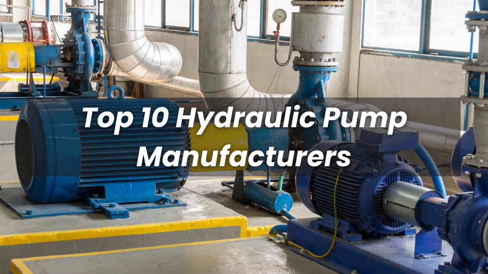
The highest quality hydraulic pumps come from the highest quality hydraulic pump manufacturers. Finding the highest quality hydraulic pump manufacturers can be hard, which is why we have we listed out some of our favorites on this page. All of those whom we have listed come highly recommended with years of experience. Find their information nestled in between these information paragraphs.
Before checking out any of these suppliers, we recommend you take some time to jot down your specifications. That way, you will have an easier time figuring out which ones have potential for you and which ones do not. Plus, when you are ready to talk to a supplier, your list will help you steer the conversation. Do not forget to include in your list the nitty-gritty details like your timeline, your budget and your delivery preferences.
Once you have put together you list, get to browsing. Pick out three or four hydraulic pump supply companies to which you’d like to speak, then reach out to each of them. After you’ve spoken with representatives from each company, decide which one will best serve you, and get started on your project.

This website is using a security service to protect itself from online attacks. The action you just performed triggered the security solution. There are several actions that could trigger this block including submitting a certain word or phrase, a SQL command or malformed data.

www.powermotiontech.com is using a security service for protection against online attacks. An action has triggered the service and blocked your request.
Please try again in a few minutes. If the issue persist, please contact the site owner for further assistance. Reference ID IP Address Date and Time 8bf2006c85a66667641f5dd58dcb3d35 63.210.148.230 03/11/2023 09:02 PM UTC

Hydraulic Pumps are any of a class of positive displacement machines used in fluid power applications to provide hydraulic flow to fluid-powered devices such as cylinders, rams, motors, etc. A car’s power-steering pump is one example where an engine-driven rotary-vane pump is common. The engine’s gear-type oil pump is another everyday example. Hydraulic pumps can be motor-driven, too, or manually operated. Variable displacement pumps are especially useful because they can provide infinite adjustment over their speed range with a constant input rpm.
Pumps produce flow. Pressure is resistance to flow. Whereas centrifugal pumps can run against blocked discharges without building up excess pressure, positive-displacement pumps cannot. Hydraulic pumps, like any positive-displacement pump, thus require overpressure protection generally in the form of a pressure-relief valve. Over-pressure relief is often built into the pump itself.
Hydraulic systems are used where compact power is needed and where electrical, mechanical, or pneumatic systems would become too large, too dangerous, or otherwise not up to the task. For construction equipment, hydraulic power provides the means to move heavy booms and buckets. In manufacturing, hydraulic power is used for presses and other high-force applications. At the heart of the hydraulic system is the pump itself and the selection of a correct hydraulic pump hinges on just what the hydraulic system will be expected to do.
Axial piston pumps use axially mounted pistons that reciprocate within internal cylinders to create alternating suction and discharge flow. They can be designed as variable-rate devices making them useful for controlling the speeds of hydraulic motors and cylinders. In this design, a swashplate is used to vary the depth to which each piston extends into its cylinder as the pump rotates, affecting the volume of discharge. A pressure compensator piston is used in some designs to maintain a constant discharge pressure under varying loads.
Radial piston pumps arrange a series of pistons radially around a rotor hub. The rotor, mounted eccentrically in the pump housing, forces the pistons in and out of cylinders as it rotates, which cause hydraulic fluid to be sucked into the cylinder cavity and then be discharged from it. Inlets and outlets for the pump are located in a valve in a central hub. An alternative design places inlets and outlets around the perimeter of the pump housing. Radial piston pumps can be purchased as fixed- or variable-displacement models. In the variable-displacement version, the eccentricity of the rotor in the pump housing is altered to decrease or increase the stroke of the pistons.
Rotary vane pumps use a series of rigid vanes, mounted in an eccentric rotor, which sweep along the inside wall of a housing cavity to create smaller volumes, which forces the fluid out through the discharge port. In some designs, the volume of the fluid leaving the pump can be adjusted by changing the rotational axis of the rotor with respect to the pump housing. Zero flow occurs when the rotor and housing axes coincide.
External Gear pumps rely on the counter-rotating motion of meshed external spur gears to impart motion to a fluid. They are generally fixed-displacement designs, very simple and robust. They are commonly found as close-coupled designs where the motor and pump share a common shaft and mounting. Oil travels around the periphery of the pump housing between the teeth of the gears. On the outlet side, the meshing action of the teeth decreases the volume to discharge the oil. The small amount of oil that is trapped between the re-meshing gears discharges through the bearings and back to the pump’s suction side. External gear pumps are very popular in fixed-displacement hydraulic applications as they are capable of providing very high pressures.
The internal gear pump uses the meshing action of an internal and external gear combined with a crescent-shaped sector element to create fluid flow. The axis of the external gear is offset from that of the internal gear, and as the two gears rotate, their coming out of and into mesh create suction and discharge zones. The sector serves as a barrier between suction and discharge. Another internal gear pump, the gerotor, uses meshing trochoidal gears to achieve the same suction and discharge zones without needing a sector element.
This article presented a brief summary of some of the common types of hydraulic pumps. For more information on additional topics, consult our other guides or visit the Thomas Supplier Discovery Platform to locate potential sources of supply or view details on specific products.
Impeller blades revolve inside the casing, rotating the surround fluids. the blades also lubricate and cool the system. Pump bearings are often made to anti-friction, to help the impeller rotate inside the casing. The pump shaft is made of steel, and its size corresponds to the size of the impeller.
A hydraulic hand pump transforms human power into hydraulic energy by combining pressure and flow. The foundation for hydraulic fluid delivery is the simple notion that a handle gives an internal piston leverage under manual pressure. The piston then pushes the hydraulic fluid into the cylinder port. Water and hydraulic fluid are the two most common fluids, and however other pressure media can also be used.
The hydraulic pressure generated can be used to test, calibrate, and adjust various measuring instruments and tools. Hydraulic hand pumps are widely used to load and test mechanical parts when a user requires precise adjustments. They are also used in lifting and lowering heavy things in material handling equipment, which similarly necessitates precise control over the movement of the objects.
The working medium, requisite pressure range, drive type, etc., are only a few of the functional and hydraulic system requirements that are considered when manufacturing hydraulic pumps. In addition, there are numerous design philosophies and hydraulic pump combinations to choose from. Due to this, only a few pumps can completely fulfill all needs. The most common types of hydraulic pumps have already been described.
The use of hydraulic pumps is still common in industrial settings. Elevators, conveyors, mixers, forklifts, pallet jacks, injection molding machines, presses (shear, stamping, bending, etc.), foundries, steel mills, and slitters are examples of equipment used in material handling. With an application"s need, a hydraulic pump is more likely to be used.
Additionally, hydraulic pumps are used in every conceivable mobile or industrial hydraulic machine. They are used on many different pieces of gear, such as excavators, cranes, loaders, tractors, vacuum trucks, forestry equipment, graders, dump trucks, and mining equipment. Mobile applications use hydraulic pumps more commonly than industrial applications since industrial devices typically don"t use electric actuators.

There are typically three types of hydraulic pump constructions found in mobile hydraulic applications. These include gear, piston, and vane; however, there are also clutch pumps, dump pumps, and pumps for refuse vehicles such as dry valve pumps and Muncie Power Products’ Live PakTM.
The hydraulic pump is the component of the hydraulic system that takes mechanical energy and converts it into fluid energy in the form of oil flow. This mechanical energy is taken from what is called the prime mover (a turning force) such as the power take-off or directly from the truck engine.
With each hydraulic pump, the pump will be of either a uni-rotational or bi-rotational design. As its name implies, a uni-rotational pump is designed to operate in one direction of shaft rotation. On the other hand, a bi-rotational pump has the ability to operate in either direction.
For truck-mounted hydraulic systems, the most common design in use is the gear pump. This design is characterized as having fewer moving parts, being easy to service, more tolerant of contamination than other designs and relatively inexpensive. Gear pumps are fixed displacement, also called positive displacement, pumps. This means the same volume of flow is produced with each rotation of the pump’s shaft. Gear pumps are rated in terms of the pump’s maximum pressure rating, cubic inch displacement and maximum input speed limitation.
Generally, gear pumps are used in open center hydraulic systems. Gear pumps trap oil in the areas between the teeth of the pump’s two gears and the body of the pump, transport it around the circumference of the gear cavity and then force it through the outlet port as the gears mesh. Behind the brass alloy thrust plates, or wear plates, a small amount of pressurized oil pushes the plates tightly against the gear ends to improve pump efficiency.
A cylinder block containing pistons that move in and out is housed within a piston pump. It’s the movement of these pistons that draw oil from the supply port and then force it through the outlet. The angle of the swash plate, which the slipper end of the piston rides against, determines the length of the piston’s stroke. While the swash plate remains stationary, the cylinder block, encompassing the pistons, rotates with the pump’s input shaft. The pump displacement is then determined by the total volume of the pump’s cylinders. Fixed and variable displacement designs are both available.
With a fixed displacement piston pump, the swash plate is nonadjustable. Its proportional output flow to input shaft speed is like that of a gear pump and like a gear pump, the fixed displacement piston pump is used within open center hydraulic systems.
As previously mentioned, piston pumps are also used within applications like snow and ice control where it may be desirable to vary system flow without varying engine speed. This is where the variable displacement piston pump comes into play – when the hydraulic flow requirements will vary based on operating conditions. Unlike the fixed displacement design, the swash plate is not fixed and its angle can be adjusted by a pressure signal from the directional valve via a compensator.
Flow and Pressure Compensated Combined – These systems with flow and pressure compensation combined are often called a load-sensing system, which is common for snow and ice control vehicles.
Vane pumps were, at one time, commonly used on utility vehicles such as aerial buckets and ladders. Today, the vane pump is not commonly found on these mobile (truck-mounted) hydraulic systems as gear pumps are more widely accepted and available.
Within a vane pump, as the input shaft rotates it causes oil to be picked up between the vanes of the pump which is then transported to the pump’s outlet side. This is similar to how gear pumps work, but there is one set of vanes – versus a pair of gears – on a rotating cartridge in the pump housing. As the area between the vanes decreases on the outlet side and increases on the inlet side of the pump, oil is drawn in through the supply port and expelled through the outlet as the vane cartridge rotates due to the change in area.
Input shaft rotates, causing oil to be picked up between the vanes of the pump which is then transported to pump outlet side as area between vanes decreases on outlet side and increases on inlet side to draw oil through supply port and expel though outlet as vane cartridge rotates
A clutch pump is a small displacement gear pump equipped with a belt-driven, electromagnetic clutch, much like that found on a car’s air conditioner compressor. It is engaged when the operator turns on a switch inside the truck cab. Clutch pumps are frequently used where a transmission power take-off aperture is not provided or is not easily accessible. Common applications include aerial bucket trucks, wreckers and hay spikes. As a general rule clutch pumps cannot be used where pump output flows are in excess of 15 GPM as the engine drive belt is subject to slipping under higher loads.
What separates this pump from the traditional gear pump is its built-in pressure relief assembly and an integral three-position, three-way directional control valve. The dump pump is unsuited for continuous-duty applications because of its narrow, internal paths and the subsequent likelihood of excessive heat generation.
Dump pumps are often direct mounted to the power take-off; however, it is vital that the direct-coupled pumps be rigidly supported with an installer-supplied bracket to the transmission case with the pump’s weight at 70 lbs. With a dump pump, either a two- or three-line installation must be selected (two-line and three-line refer to the number of hoses used to plumb the pump); however, a dump pump can easily be converted from a two- to three-line installation. This is accomplished by inserting an inexpensive sleeve into the pump’s inlet port and uncapping the return port.
Many dump bodies can function adequately with a two-line installation if not left operating too long in neutral. When left operating in neutral for too long however, the most common dump pump failure occurs due to high temperatures. To prevent this failure, a three-line installation can be selected – which also provides additional benefits.
Pumps for refuse equipment include both dry valve and Live Pak pumps. Both conserve fuel while in the OFF mode, but have the ability to provide full flow when work is required. While both have designs based on that of standard gear pumps, the dry valve and Like Pak pumps incorporate additional, special valving.
Primarily used on refuse equipment, dry valve pumps are large displacement, front crankshaft-driven pumps. The dry valve pump encompasses a plunger-type valve in the pump inlet port. This special plunger-type valve restricts flow in the OFF mode and allows full flow in the ON mode. As a result, the horsepower draw is lowered, which saves fuel when the hydraulic system is not in use.
In the closed position, the dry valve allows just enough oil to pass through to maintain lubrication of the pump. This oil is then returned to the reservoir through a bleed valve and small return line. A bleed valve that is fully functioning is critical to the life of this type of pump, as pump failure induced by cavitation will result if the bleed valve becomes clogged by contaminates. Muncie Power Products also offer a butterfly-style dry valve, which eliminates the bleed valve requirement and allows for improved system efficiency.
It’s important to note that with the dry valve, wear plates and shaft seals differ from standard gear pumps. Trying to fit a standard gear pump to a dry valve likely will result in premature pump failure.
Encompasses plunger-type valve in the pump inlet port restricting flow in OFF mode, but allows full flow in ON mode lowering horsepower draw to save fuel when not in use
Wear plates and shaft seals differ from standard gear pumps – trying to fit standard gear pump to dry valve likely will result in premature pump failure
Live Pak pumps are also primarily used on refuse equipment and are engine crankshaft driven; however, the inlet on a Live Pak pump is not outfitted with a shut-off valve. With a Live Pak pump, the outlet incorporates a flow limiting valve. This is called a Live Pak valve. The valve acts as an unloading valve in OFF mode and a flow limiting valve in the ON mode. As a result, the hydraulic system speed is limited to keep within safe operating parameters.
Outlet incorporates flow limiting valve called Live Pak valve – acts as an unloading valve in OFF mode and flow limiting valve in ON mode restricting hydraulic system speed to keep within safe operating parameters
High-performance FlowMaster hydraulic pumps combine rotary-driven pump motors with reciprocating pump tubes and flexible control features that perform in desert heat ...
RS PRO hydraulic barrel pumps, designed for use with 40 gallon metal drums, which will pump up to Hypoid 90 viscosity. These hand pumps fearure nitrile rubber (NBR) seals ...
As the new member of the Hydro product range, the hydraulic diaphragm metering pump Hydro/ 2 API 675 (HA2a) meets the requirements of API 675. The pumps stand ...
The radial piston pump type R consists of valve-controlled pump elements arranged in star form around an eccentric. For large flow rates, up to 42 pump elements can be set up in 6 stars ...
... axial piston pump type V60N is designed for open circuits in mobile hydraulics and operate according to the swash plate principle. They are available with the option of a thru-shaft for operating additional ...
... for open circuits in mobile hydraulics and operate according to the swash plate principle. They are available with the option of a thru-shaft for operating additional hydraulic pumps ...
The K3VG series are swash-plate type axial piston pumps which give excellent performance in high flow industrial applications in a compact and cost-effective package.
... Parker’s hydraulic truck pump series F1 featuring high self-priming speed and high efficiency and is one of the leading truck pumps in the market. The F1 pump provide ...
... Piston Pumps provide fixed-displacement power in a unique miniature design. Engineered for open-circuit systems, they bring flexibility to your operation. Compact Piston Pumps ...
... accessibly priced, aluminium gear pumps and motors are among the components most widely utilized in the field of hydraulic applications. Gear pumps are used to operate hydraulic ...
... and very compact for easier and inexpensive installations. Bent Axis pumps-motors will mount directly to virtually any Bezares PTO in our extensive line.
... displacement bent axis piston pumps were developed with spherical head pistons. This provides extremely high performance and high pressure ratings on a long life span unit. Flow rates range from 10.5 to 29 GPM. These ...
Sophisticated technology in the smallest space - this is what our Alfra electro-hydraulic pumps stand for. Due to the compact design, the powerful drive units also find room when things ...
Our hydraulic cylinder with a quick coupling has a performance up to 11 tons pressure – with a deadweight of only 2,5 kg. The SKP-1 is compatible with the ALFRA foot pump. Your advantage: Your hands are ...
... our ALFRA hydraulic cylinder SKP-1. In a team with the hydraulic pump DSP-120 it is capable to take a variety of challenges – because the SKP-1 working with a maximum operating pressure ...
... quality carbon steel, the pump design features allow it to work with viscous lubricants without any additional complicated priming procedures. The pump, when combined with a suitable ...
The Bansbach hydraulic pump series is an industrial offering that permits a wide range of applications, taking into account its configurable height mechanism. This device allows easy task execution with ...
... alkitronic hydraulic pumps with electric or pneumatic drive provide fast operating speed, reliability, and safety. They are designed for permanent operation. Our hydraulic ...
Of the same design as the XPi pumps, the XAi fixed displacement pumps are with SAE flange and shaft and are available in displacements from 18 to 63 cc/rev.
Bent axis XPi pumps are specially designed to meet the needs of truck equipment. Their compact design allows a direct flange-mounting on the PTO. All models are of 7 piston design to ensure optimal flow ...
With their unique design, PA-PAC pumps offer a robust and durable solution to the high pressure needs of truck applications. Combining the automatic dual direction of rotation, high operating pressure (up to 500 bar peak), ...


 8613371530291