
raymarine hydraulic pump installation manufacturer

I suspect that if you consulted with Sea Star"s support team, you would find that the two capped ports are for an optional hydraulic fluid reservoir and for the additional hydraulic hose from the autopilot"s hydraulic pump shown within the diagram below.
Should no hydraulic fluid reservoir have been installed with your helm pump, then the helm pump would be acting as a limited capacity reservoir for hydraulic fluid. One of the caps which you have referenced will need to be removed to accommodate connecting the additional hydraulic hose from the autopilot"s hydraulic pump.
Regarding the location of the autopilot"s hydraulic pump, best performance will be achieved when the pump has been located in close proximity to the steering ram. The pump"s installation location should also be protected from exposure to moisture associated with rain and waves. However, it should be noted that it sometimes not practical, particularly in smaller boats, to install the autopilot hydraulic pump in very close proximity to the steering ram. In smaller boats, the location of the autopilot hydraulic pump is less important with respect to the performance of the autopilot. However, it is key to ensure that the autopilot hydraulic pump is located at a lower height relative to the helm pump and that the hose is run in a continuously upward direction from the autopilot hydraulic pump to the helm pump.
I have broken this post out of a previous thread I had (Raymarine forum / Raymarine Forums / Multifunction Displays / [CA11] Upgrades to my 2006 Four Winns ) because it only deals with the autopilot, and is independent of the replacement of the MFD.
To start, my boat is on the hard, shrink wrapped with no access to the engine compartment where the hydrolic pump is. The electronics and Autopilot are part of the original equipment (2006 Four Winns 348) installed by the manufacturer.
Also, in the previous thread, the Moderator identified the existing Autopilot as probably a S1G, with which I concur. The suggestion was that an ACU-150 could be installed as a repllacement for the S1G IF the pump is a TYPE 1.
Reviewing the wiring diagrams for the boat, shows that the circuit breaker for the current AP is a 10 Amp, with 14AWG wiring. Installation instructions for the S1G specifies a 20 Amp circuit breaker with 14AWG wiring. As I understand it, this supplies power to both the S1G module and the pump, with the pump being the largest draw of power.
Q5: If I wait until I open the boat (nice weather and no snow) to purchase the equipment, how do I identify the type of pump. Remember this is 2006 era equipment. I understand that this is probably the best course. It is just a matter of timing.

Distributed by Any reference to Raytheon or RTN in this manual should be interpreted as Raymarine. The names Raytheon and RTN are owned by the Raytheon Company.
Hydraulic Pump Installation Guide Drives covered: M81120 Type 1 Hydraulic Pump 12 V M81119 Type 1 Hydraulic Pump 24 V M81121 Type 2 Hydraulic Pump 12 V M81123 Type 2 Hydraulic Pump 24 V M81122 Type 3 Hydraulic Pump 12 V...
EMC conformance All Raymarine equipment and accessories are designed to the best industry standards for use in the recreational marine environment. The design and manufacture of Raymarine equipment and...
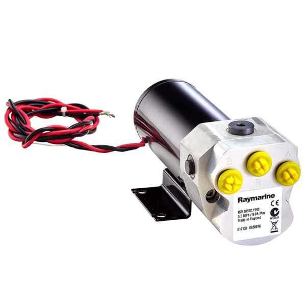
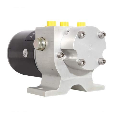
(also known as the Raymarine reversing hydraulic pump). This product is intended to operate the boat’s steering mechanism as part of a Raymarine autopilot system. It is primarily designed for use on boats with an existing hydraulic steering system. Alternatively, you can use this pump on a boat with mechanical steering in conjunction with a secondary steering ram.
Other information Pump dimensions Type 1 (12 V) and Type 2 pumps Figure 2: Type 1 (12 V) and Type 2 pump dimensions Hydraulic Pump - Installation Guide Type 1 (T1) Type 2 (T2) M81120 (12 V) M81121 (12 V)
Hydraulic Pump - Installation Guide Type 3 pump Figure 3: Type 3 pump dimensions Installation instructions Parts required To install this drive you will need: • Parts supplied: • • • Additional parts: • • • Note: Make sure you have obtained these additional parts before you start installation.
Connect to the course computer. Complete the post-installation checks. 1. EMC installation guidelines All Raymarine equipment and accessories are designed to the best industry standards for use in the recreational marine environment. Their design and manufacture conforms to the appropriate...
• Raymarine specified cables are used. Cutting and rejoining these cables can compromise EMC performance and must be avoided unless doing so is detailed in the installation manual.
Connections to other equipment If your Raymarine equipment is to be connected to other equipment using a cable not supplied by Raymarine, a suppression ferrite MUST always be attached to the cable near to the Raymarine unit. 2. Pump mounting Mount the hydraulic pump: •...
Hydraulic Pump - Installation Guide • Try to keep hydraulic fluid loss to a minimum when installing the pump. This will reduce the time and effort required to bleed the system of trapped air after installation: • • WARNING: Before disconnecting any pipes on pressurized systems, you MUST release the pressure at the reservoir by following the manufacturer’s instructions.
Connect the autopilot pump to the steering system as shown in Figure 5. Reservoir pipe Autopilot pump Figure 5: Autopilot pump location for two line systems Hydraulic Pump - Installation Guide Helm pump Check valve (if required) Ram pipes Steering ram...
Hydraulic Pump - Installation Guide Two line pressurized systems Two line pressurized systems have an external pressurized reservoir. This reduces the possibility of introducing air into the system and reduces any steering ‘sponginess’ caused by pipe expansion. Connect the autopilot pump to the steering system as shown in Figure 6.
Connect the autopilot pump to the steering system as shown in Figure 7. Figure 7: Autopilot pump location for three line systems Helm pump Check valve Reservoir pipe Autopilot pump Hydraulic Pump - Installation Guide Ram pipes Steering ram...
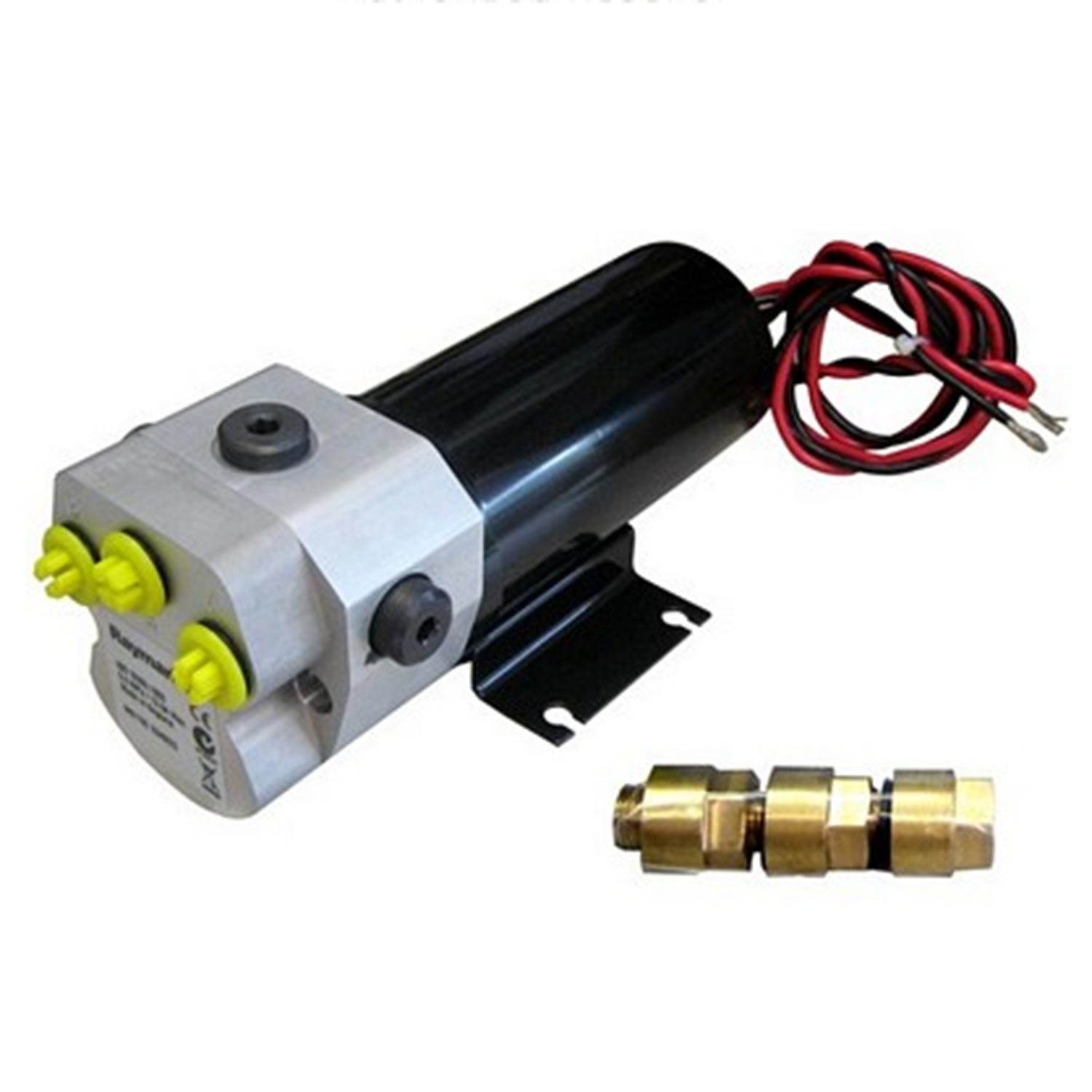
Make sure the power supply is switched off before you make any electrical connections. The hydraulic pump has electrical connections for its motor: a red and a black cable. Note: To meet current EMC legislation, you must NOT untwist the pump cables, and you must NOT remove the suppression ferrite.
M81167) across these pipes (as shown in Figure 9). Connect the bypass valve to the CLUTCH terminals on the course • computer using at least 1.5 mm Hydraulic Pump - Installation Guide Cable gauge (AWG) up to 3 m (10 ft)
Hydraulic Pump - Installation Guide Note: Follow the manufacturer’s instructions for mounting the hydraulic ram and reservoir. Figure 9: Connecting to a secondary steering ram 5. Post-installation check WARNING: Keep clear of moving steering systems at all times. Protect moving parts from access during normal use.
Bleeding the system Bleeding the hydraulic system correctly is one of the most important steps when installing the autopilot hydraulic pump. If there is any air in the system the steering will feel spongy, particularly when you turn the wheel to hardover.
Authorized Service Representatives. If you encounter any difficulties with this product, please contact either your national distributor, or your service representative, or the Raymarine Technical Services Call Center. Refer to the back cover or the Worldwide Distributor List for contact details.
Fax +44 (0)23 9269 4642 www.raymarine.com Raymarine Technical Services Call Center UK: +44 (0)23 9271 4713 or +44 (0)23 9269 3611 ext. 1083 Hydraulic Pump - Installation Guide Raymarine Inc 22 Cotton Road, Suite 280 Nashua NH 03063-4219, USA Telephone +1 603 881 5200 Fax +1 603 864 4756 www.raymarine.com...

Raymarine evolution systems accommodate hydraulic, mechanical and power assisted stern drive systems. The Drive unit is the part that interfaces with your vessel’s steering system to keep you on the right course. Raymarine has a broad range of drive units to match almost any type of steering system. Raymarine Evolution pilots connect to hydraulic steering systems using a rugged hydraulic pump matched to the capacity of the hydraulic steering system. If your system is hydraulic You’ll need to find out the size (in cc) of the hydraulic cylinder ram(s) mounted to the rudder or inboard engined boats, or to the drive unit on outboard engined boats. Your steering system documentation will have this information.
When seeking an autopilot for a vessel with hydraulic steering (not to be confused with cable driven / power assisted steering common to I/O powered vessels), the first step is to determine the cubic capacity (specified in cubic centimeters (cc) or cubic inches (ci)) of the vessel"s steering ram(s). The cubic capacity of the steering ram(s) is typically stamped onto a plate affixed to the steering ram. Alternatively, the manufacturer of the steering ram may be contacted to obtain this information. Should the vessel be equipped with more than one steering ram, then it will need to be determined whether the steering rams have been plumbed in series or parallel. The total capacity of hydraulic fluid that will need be pumped through steering rams which have been plumbed in series will be equal to the capacity of one of the steering rams. The total capacity of hydraulic fluid that will need be pumped through steering rams which have been plumbed in parallel will be equal to sum of the capacities of each steering ram.
After having determined the capacity of hydraulic fluid that will need be pumped through steering ram(s), an autopilot hydraulic pump will be selected. As the capacities of the hydraulic pumps overlap, some discretion should be used in selecting the appropriate pump for the vessel. Service life and performance of the autopilot will typically be maximized by installing the higher rated of two hydraulic pumps which support the capacity of hydraulic fluid which will need be pumped through steering ram(s). One should not install a hydraulic pump having a minimum specified hydraulic capacity which exceeds the capacity of hydraulic fluid which will need be pumped through steering ram(s).
NOTE: When used with an ACU-150 or ACU-200, a Type 0.5 pump may be used in hydraulic steering systems equipped with rams having capacities up to 150cc (9 cu. in.). When used with the ACU-100, it is recommended that it not be used in hydraulic steering systems equipped with rams having capacities greater than 110cc (6.7 cu. in.) in offshore and/or heavy use applications. The ACU-200 may be used with 12V or 24V systems, while the ACU-150 may only be used with 12V systems.
After having determined the model of hydraulic pump that will be installed onboard the vessel, then the model of Evolution Autopilot Actuator Control Unit (ACU) will be determined based upon the model of autopilot hydraulic pump that will be installed onboard the vessel. See the table above specifying the model of Evolution Autopilot ACU which will be used for each model of Raymarine autopilot hydraulic pump.
The remaining components which make up an Evolution autopilot for a hydraulically steered vessel include an EV-1 Evolution Autopilot Sensor Core, a p70s or p70Rs Autopilot Control Head(s), and an optional rudder reference transducer.
Note: autopilot control heads are optional, but recommended, for vessels equipped with Raymarine a/c/e/eS/gS-Series or Axiom MFDs. A p70s or p70Rs Autopilot Control Head must be installed when interfacing an Evolution autopilot system any other model of Raymarine MFD or third party chartplotting device.
While the components for Evolution autopilots may be individually purchased and part number found here, Raymarine offers the following Evolution Autopilot bundles which include: EV-1 Sensor Core, ACU, hydraulic pump, Evolution Autopilot SeaTalkng Cabling Kit. The following Evolution autopilot bundles are available for hydraulically steered powerboats:
Note: The information specified within this FAQ may also be found on the Hydraulic tab of Raymarine"s Drive Unit Selection web page and Table 1-1 of the Raymarine Hydraulic Pump Installation Guide. As product specifications and product documentation are subject to change, it is recommended that customers seeking the latest product specifications consult Raymarine"s product web pages and the latest Raymarine product manuals accessible via Raymarine"s Manuals and Docs web page.
Raymarine Evolution pilots connect to hydraulic steering systems using a rugged hydraulic pump matched to the capacity of the hydraulic steering system.
You"ll need to find out the size (in cc) of the hydraulic cylinder ram(s) mounted to the rudder or inboard engined boats, or to the drive unit on outboard engined boats. Your steering system documentation will have this information.
If you cannot find the ram size on your steering system documentation, you can look on the cylinder ram itself for the brand and model number. Once you have the number use our hydraulic cylinder ram cross-reference guide to determine which hydraulic autopilot pump is compatible with your vessel"s hydraulic steering system.
In some systems with dual steering rams in parallel, cylinder capacity is the total of both rams. Rams in series only require single capacity valve. Hydraulic steering systems with steering rams over 500cc require our larger constant running pump used in conjunction with the relevant ACU - contact Raymarine for details.


 8613371530291