
running hydraulic pump dry manufacturer
Dry running a pump can cause all kinds of serious problems, yet many operators are unaware of the dangers. When a pump runs dry, it generates heat and force it was never designed to handle, leading to wear and tear that can quickly add up to inflated repair costs. Avoiding dry running is highly important, but it makes sense to learn how negative it can be in order to fully understand the severity of the phenomenon.
When a pump runs dry, it runs without any liquid going through it. This is always a bad idea, as it puts an inordinate amount of strain on the pump’s moving parts.
Instead of circulating fluid, a dry running pump pushes nothing but air around, leading to friction, heat, and destruction of delicate internals. A hydraulic pump is normally designed to run while filled with fluid. As it runs, the fluid inside it helps to preserve its internal pieces, cooling them and even assisting in centreing moving elements such as the rotor.
Pumps that operate at particularly high pressure can suffer considerable cavitation simply from fluid-derived vapor; completely dry running a finely tuned pump is significantly worse for its longevity. Even self-priming pumps should only be run once the proper amount of fluid is inside, as they can withstand only partial dry conditions while priming themselves.
Running your hydraulic pump dry is likely to result in disaster, wearing it out prematurely via the aforementioned heat, violent vibrations, or complete lock-up/seizure of important parts, costing you money to fix or replace.
Running a hydraulic pump dry can lead to a large variety of issues with the pump’s parts and the rest of your hydraulic system as well. Here are a few common problems that dry running can cause:
High temperatures caused by dry running can ruin your pump, pitting its housing and causing leaks.¹ If heat and pressure are excessive enough, the housing boss may deform, potentially stopping your impeller from rotating freely and rendering your pump functionally useless. In many cases, a severely damaged, leaking pump is likely to need replacing, which can run your costs up much further than anticipated.
As is the case for the housing of your pump, the impeller is susceptible to damage done by excessive heat during use. Dry running your pump causes friction, and this friction is strong enough to heat up the impeller, causing it to melt.² Even minor melting is severely detrimental to your pump’s performance, potentially causing it to seize up and stop working at all. Taking it apart for repair is usually an involved and costly exercise best avoided through preventive operating practices.
Internal wear caused by dry running your pump can lead to additional wear throughout the entirety of your system. This is generally caused by either excessive heat or metal particles scraped from disintegrating moving pieces within your pump travelling through the rest of your system. Metal particles, in particular, can cut and clog valve components, pipes, and tubes, leading to system failure over time.
You may need to run your pump dry for short periods of time to empty the system completely, but it is best to keep such instances as brief as possible. Once your tank or system has been emptied by the pump, it should be turned off. Do not allow it to keep running for more than a minute without any fluid.
Keeping someone in charge of monitoring your pump as it runs can help avoid unintended dry running problems. Often, a pump may be left running until a job is completed. If the pump performs its function faster than intended and all fluid is purged from the system, it will run dry and damage itself until an operator returns to turn it off. Having someone manage the pump at all times is crucial to keeping it functional.
Some companies have found an automatic means of controlling their pumps’ functions from afar. By leveraging special protective devices and control systems, it is possible to automatically stop a pump that is in danger of running dry, preserving its internal parts and averting expensive disasters.³ However, such devices incur an additional cost.
At White House Products, Ltd., we offer all manner ofpump parts to patch up a system damaged by dry running. We can also provide complete replacements as needed. Call our technical support team at +44 (0)1475 742500 to learn how we can help get your pump working again.
Dry Running is an undesirable condition which affects most pump designs and is characterised when a pump operates without an adequate amount of fluid. In most pump technologies, this leads to cavitation and critical damage to the internal pumping elements such as impellers, lobes, gears, casings, seals & bearings.
Dry running is usually related to how the pump is operated, monitored & controlled which is typically a result of human error. Companies generally rely on their operators to monitor the pumps on the line, however, problems will arise when a pump is unintentionally left running for prolonged periods of time after the intended operation has been completed. For example, during offloading of a tanker, an operator may leave the pump unattended whilst the tanker is being evacuated and the pump may over-run when the tanker is empty thus resulting in damage to the pump internals.
Dry running could lead mechanical seals to wearing quickly which could cause the pump to leak. This will allow the potentially hazardous liquid to spill putting pump operators at risk.
Dry running can damage your pump which could cause an immediate stop to your production line meaning a loss of production – delays & costs to your business
Risked cavitation if dry run for long periods of time which may require the whole pump to be replaced if there has been serious damage to the impellers in your pump
Dry Running can be extremely costly to your business so please check with your supplier or the pump manufacturer whether the pump you’ve purchased can be dry run before operating it.
When using most pump designs, such as Rotodynamic as well as Reciprocating and Rotary Positive Displacement Pumps, most companies need to install protection and control devises on the pumps and system to ensure that the pump is stopped immediately after the pumping operation is complete, or in the absence of fluid at the pump suction or source.
Pressure or Level Switch Protection:Pressure Switches fitted to the suction pipe or port of the pump(s) or Float Switches/Electrode Relays in the Supply tank
Engineers on-site and Operators spend significant amounts of time ensuring pumps are properly installed & primed, significantly increasing the cost and complexity of the installation. However, despite all these efforts, the ever-present possibility of human error, malfunctioning control and monitoring equipment, unpredictable events & improper use of equipment means that Dry Running is never completely eradicated. As a result, plant owners are constantly in search of technology and solutions which can prevent or avoid the costly and damaging effects of Dry Running in order to reduce maintenance costs, increase throughput and alleviate pressures put onto operators to constantly monitor, control and protect their equipment on the line.
There are a variety of standard accessories that can be used to control pumping equipment to protect is from dry running such as pressure and temperature sensors. Additional accessories and expensive sealing systems aren’t always the answer. Not all pumps are created equally, in fact, at Tapflo UK we have a variety of pump solutions that will allow you to dry run your pump without causing damage to it. Need your pump to run dry? Let us know when you call us.
Tapflo offer a range of pump technologies that have the added benefit of being able to dry run, including our Diaphragm Pumps and Peristaltic Pumps which can run dry indefinitely without damaging the pump.
Due to their design and construction, both of these pumping technologies are able to operate under dry conditions without experiencing common wear problems associated with dry running. Not only does this alleviate the pressure put on the operator, but it also simplifies the pumping system and reduces the cost of installation and ownership significantly. Of course, these designs, on their own, do not overcome the energy costs affiliated with overrunning equipment, to improve this, Tapflo offers dry run protection devices such as our Pneumatic Guardian System for Diaphragm Pumps which automatically stops your pump when the pumping process is complete.
In summary, Tapflo UK have a full range of pumping solutions which can either protect equipment from Dry Running or indeed avoid problems associated with Dry Running completely! Let’s discuss your options today.

Anyone familiar with industrial magnetic drive (mag drive) pumps has been asked about dry running the pump. After all, a dishwasher and washing machine at home does that all the time. There are bearing materials that allow that, right? Sure, a qualified “yes,” but it is time to take a closer look at dry running.
Dry running, except in the literal sense, is a misnomer. Industrial pumps are mechanically sealed or sealless and can suffer from the results of what the industry has dubbed “dry run operation.” This article will focus on the mag drive pump configuration with silicon carbide (SiC) bearing components, which is one of the two sealless types of rotodynamic centrifugal pumps.
Mag drive pumps have product-lubricated bearings that require liquid to be present for proper operation. These hydrodynamic (plain) bearings depend on a fluid barrier separating the bearing components that becomes a wedge when there is relative motion between the two surfaces. When this fluid barrier is disrupted, the two surfaces will touch and can lead to component damage. This effect can be cumulative, resulting in component failure when limits are reached.
If the SiC surfaces touch during operation, the components can break in a short time (depending on several factors). This does not mean the pump stops operating immediately. The broken SiC pieces may still support the shaft well enough to allow rotation of the pump rotor. Broken SiC can be detected by increased vibration and often a power increase. The condition of the pump will only get worse if operation is continued.
When the pump loses suction, it should be shut down immediately. Damage to the SiC components can occur in a matter of seconds. Using a power monitor to detect when the motor load has suddenly changed, such as when the pump loses suction, will protect major pump components. Continued operation without adequate liquid at the suction can quickly lead to severe damage of the SiC components.
For long life, the pump requires only that there be liquid available, operation within the pump flow range of the curve, and within the pump design limits. Please note that it is best to start the pump against a partially closed (about a quarter open) discharge valve. The suction valve should always be open when operating and only closed when the pump must be isolated for maintenance reasons.
excessive temperature that causes pumped liquid (lubricating flow) to vaporize at the bearing component surfaces—or not enough internal system pressure to keep the pumped fluid in liquid state as it passes through the pump
Specially treated sintered SiC is available from a number of suppliers to provide enhanced dry-running capabilities in the case of a system upset condition. Some manufacturers use coatings that adhere to the substrate SiC, while others use infusion methods that mechanically integrate the coating into the base material. All of these are called diamond-like coatings (DLC) in the industry. These treatments substantially reduce the surface coefficient of friction compared to that of standard sintered SiC. Less friction during system upset and other dry run conditions generate less heat, reducing the potential for bearing component breakage from mechanical contact or thermal shock.
In reference to pumping equipment and product lubricated bearings, no one recommends that the pump be operated without liquid passing through it. There is some residual liquid that remains when the unit loses suction, but that will quickly be pressed out of the sides of the bearing components with continued operation. Vaporization of the liquid can occur quickly, depending on the size of the pump.
Definitive dry run times would require specific testing of the pump size and conditions of service in question. For small pumps under 2 horsepower (hp), testing has shown that the dry run time is minutes and can be stretched to more than an hour for the smallest pumps with the DLC coated bearings. The greater the power input to the pump, the shorter the time period before damage occurs in the bearing system. For larger pumps in the 50-plus-hp range, while DLC coatings will still help, the time before damage occurs remains quite short. Energizing the motor to check rotation of a pump without DLC coated bearings or liquid in the unit will likely result in some bearing damage. Damage from dry running will initially appear as cracked or chipped SiC components. As the liquid vanishes and the rotating ceramic components come in contact with stationary components, the SiC can shatter, breaking into small pieces. Continued operation damages more pump components such as the shaft, rear casing, casing cover and impeller—all of which are costly parts. This type of damage to the pump is preventable.
Again, it is recommended that the pump be protected by a power monitor and that the low power trip point be set at a level representing the first indication that suction has been lost. Setting the low trip point time delay at less than 2 to 3 seconds can prevent tripping of the pump when a large bubble of vapor/air vents through the pump without losing suction. Trying to run longer to empty the suction line of product will result in damage to the pump that is more costly than the small amount of product that may remain in the suction line. A properly set power monitor will save money for the pump owner in several enterprise accounts.
Lined, mag drive pumps use either SiC or nonmetallic bearing materials. Some of the latter may have enhanced lubricity but are still subject to the same axioms of running with compromised lubrication.
Canned motor pumps, the other sealless centrifugal type, typically use softer bearing materials including carbon that are more lubricious, but susceptible to wear. These require a bearing monitor system to avoid component damage.
With mechanically sealed pumps, seal faces operate on a similar hydrodynamic film and require the same type of lubrication. They will not run dry long without damage either.

Ace developed the first hydraulic motor driven pump at the request of John Deere in 1969. Many of the original pumps are still operating today after more than 30 years of service.
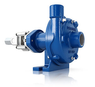
Centrifugal pump design provides good resistance to abrasive solutions and extra flow for agitation. The advantages of the hydraulic motor driven pump are mounting versatility, customized performance, and ease of maintenance. All hydraulic driven pumps are equipped with a stainless steel shaft and wear ring for excellent corrosion resistance.MOUNTING VERSATILITY:The location of the pump is not tied to the PTO or engine drive shaft; the pump can be mounted in a variety of locations to suit application requirements.
CUSTOMIZED PERFORMANCE: The performance is dependent on the supply of hydraulic oil to the motor and not necessarily tied to engine speed. A hydraulic driven pump can produce higher pressures than PTO or belt driven pumps. They can also hold constant pressure at varying engine speeds on closed center hydraulic systems.
EASY MAINTENANCE: On a hydraulic driven pump there are no belts to align or break. Separate pump and hydraulic motor shafts simplify repair and replacement. Two main pump bearings support shaft loads. All pumps are equipped with easily replaceable FKM mechanical seals.
The Ace gear type hydraulic motor is more efficient than gerotor type motors, and is less subject to damage by contamination than the gerotor design. A built-in needle valve allows for the bypass of up to 9 GPM excess hydraulic fluid on open center systems. The standard motor has a reverse flow check valve which prevents backward hookup and a coasting check which protects the motor seal from the flywheel effect of the impeller. A restrictor orifice is included with pump models recommended for pressure compensating closed center systems. The Ace Internet Hydraulic Selection Guide is here to help in finding the proper hydraulic pump for your tractor.
The 206 motor requires 7 GPM (26.5 LPM) maximum hydraulic fluid input and fits virtually all tractor hydraulic systems. Recommended for:Pressure Compensating Closed Center Systems
The 206 motor requires 7 GPM (26.5 LPM) maximum hydraulic fluid input and fits virtually all tractor hydraulic systems. Recommended for:Pressure Compensating Closed Center Systems
The 310 motor requires 16 GPM (60.6 LPM) maximum hydraulic fluid input. Recommended for:Large Open Center Systems up to 24 GPM (90.9 LPM) using internal needle valve bypass.
The 206 motor requires 7 GPM (26.5 LPM) maximum hydraulic fluid input and fits virtually all tractor hydraulic systems. Recommended for:Pressure Compensating Closed Center Systems
The 206 motor requires 7 GPM (26.5 LPM) maximum hydraulic fluid input and fits virtually all tractor hydraulic systems. Recommended for:Pressure Compensating Closed Center Systems
The 206 motor requires 7 GPM (26.5 LPM) maximum hydraulic fluid input and fits virtually all tractor hydraulic systems. Recommended for:Pressure Compensating Closed Center Systems
The 206 motor requires 7 GPM (26.5 LPM) maximum hydraulic fluid input and fits virtually all tractor hydraulic systems. Recommended for:Pressure Compensating Closed Center Systems
The Gemini DPK (Dual Pump Kit) was designed to solve these concerns. Pick any two pumps with 204 or 206 motors, and run them from one SCV remote port. Run them at different rates. Shut one pump off while leaving the other pump running. Have your rate controller send PWM signal to one or both of the pumps for precision application.
The 310 motor requires 16 GPM (60.6 LPM) maximum hydraulic fluid input. Recommended for:Large Open Center Systems up to 24 GPM (90.9 LPM) using internal needle valve bypass.
Severe duty silicon carbide seal standard - resists abrasive scratching and transfers heat away from seal faces for improved survival during short run-dry events
The 206 motor requires 7 GPM (26.5 LPM) maximum hydraulic fluid input and fits virtually all tractor hydraulic systems. Recommended for:Pressure Compensating Closed Center Systems
The 206 motor requires 7 GPM (26.5 LPM) maximum hydraulic fluid input and fits virtually all tractor hydraulic systems.Pressure Compensating Closed Center Systems
Severe duty silicon carbide seal standard - resists abrasive scratching and transfers heat away from seal faces for improved survival during short run-dry events
The 206 motor requires 7 GPM (26.5 LPM) maximum hydraulic fluid input and fits virtually all tractor hydraulic systems.Pressure Compensating Closed Center Systems
The 206 motor requires 7 GPM (26.5 LPM) maximum hydraulic fluid input and fits virtually all tractor hydraulic systems.Pressure Compensating Closed Center Systems
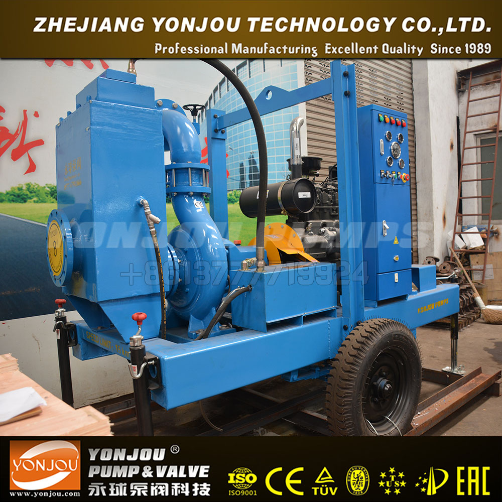
The TP30 pump provides 450 gpm of discharge capacity and can pump solids up to 3" in diameter. The TP40 has a 800 gpm of discharge capacity and can pump up to 4" diameter solids.
Hydraulic TP40 compact submersible trash pump is a light weight, efficient way to move large volumes of liquids that can contain sand, dirt and gravel very quickly. This submersible centrifugal...
Hydraulic TP40 compact submersible trash pump is a light weight, efficient way to move large volumes of liquids that can contain sand, dirt and gravel very quickly. This submersible centrifugal design requires no priming and can run dry all day wi...
The TP30 compact submersible trash pump is a light weight, efficient way to move large volumes of liquids that can contain sand, dirt and gravel very quickly. This submersible centrifugal design requires no priming and can run dry all day without ...
Submersible trash pump for dewatering construction sites. The SP20 compact submersible Hydraulic pump is a light weight, efficient way to move large volumes of liquids quickly. See flow chart to see how much hydraulic oil. 5-8gpm
Did you know you can invalidate the warranty of your final drive motor if you make the mistake of dry starting it after you’ve just installed it? Read on to learn what a dry start it, how it can damage your motor, and how to keep it from happening to you.
Many people mistakenly believe that because hydraulic fluid circulates through the hydraulic system that all you need to do is connect the hoses to the right ports and you’re good to go. Just because the hydraulic fluid circulates doesn’t mean you can attach an empty component and expect it to be ready to run. And frankly, there is no excuse for dry starting the planetary side of a final drive motor because there is no circulation of fluid to fall back on.
That damage can lead to flakes and other tiny bits of metal breaking free and contaminating the hydraulic fluid or oil once it has access to these parts. Then you have
Scratches and abrasions lead to a reduction in performance, which means that a brand new final drive motor ends up with compromised efficiency and power from the start. In short, you’ve damaged the motor immediately after installation, and dry start damage is not covered by warranties.
Before starting a hydraulic motor that is either brand new, repaired, or rebuilt, add clean, new hydraulic fluid to the hydraulic hub and make sure there is fresh gear oil in the planetary hub. That is all you need to do in order to avoid a dry start.
Just a few simple steps can help you avoid damaging your final drive hydraulic motor by dry starting it. Since damage caused by a dry start is not covered by warranty, it is all the more important that you make sure your motor has fluid and gear oil before you start it.
is your partner in providing new or remanufactured final drive hydraulic motors from a single mini-excavator to a fleet of heavy equipment. Call today so we can find the right final drive or hydraulic component for you, or check out our online store to.
If the impeller seizes, it will stop and not rotate. To correct this, the pump should be taken apart and a drill bit should be used to clean out the bore of the impeller.
A hole may develop in the rear housing, allowing liquid to escape. Or, the boss of the rear housing, which secures the pump shaft, may become deformed, which will allow the shaft to move instead of remaining stationary.
This will cause damage to the impeller and may cause the shaft to break from the impeller bouncing on it. If the pump is made from stainless steel, it is unlikely holes will develop in the rear housing or that the boss will deform. What is likely to happen is the impeller bushing will seize onto the shaft.
Generally, the larger the pump with larger and heavier impellers, the faster it will be to suffer damage. You can search our pumps for the sizes we have available.
Another factor is the liquid previously in the pump. If the liquid is ambient or cooler, it will take more time for the pump to suffer damage after it starts to run dry than if the liquid is warmer.
If you are using the pump for tank transfer and want to empty the tank, this may mean running the pump dry for a few seconds. If the pump is run dry for less than 45-60 seconds, the pump should not suffer damage. Anytime you are aware that the pump may have to be run dry to empty the tank, the operator must take care to ensure the pump is run dry for the absolute minimum amount of time. Any pump that suffers from running dry is not covered by warranty.
Dry running can be an expensive hazard on your equipment but with care and supervision, you can elongate the life of your machinery. Learn more about our maintenance best practices by contacting us.
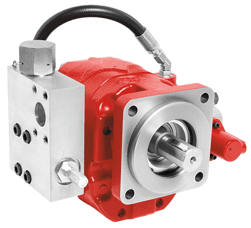
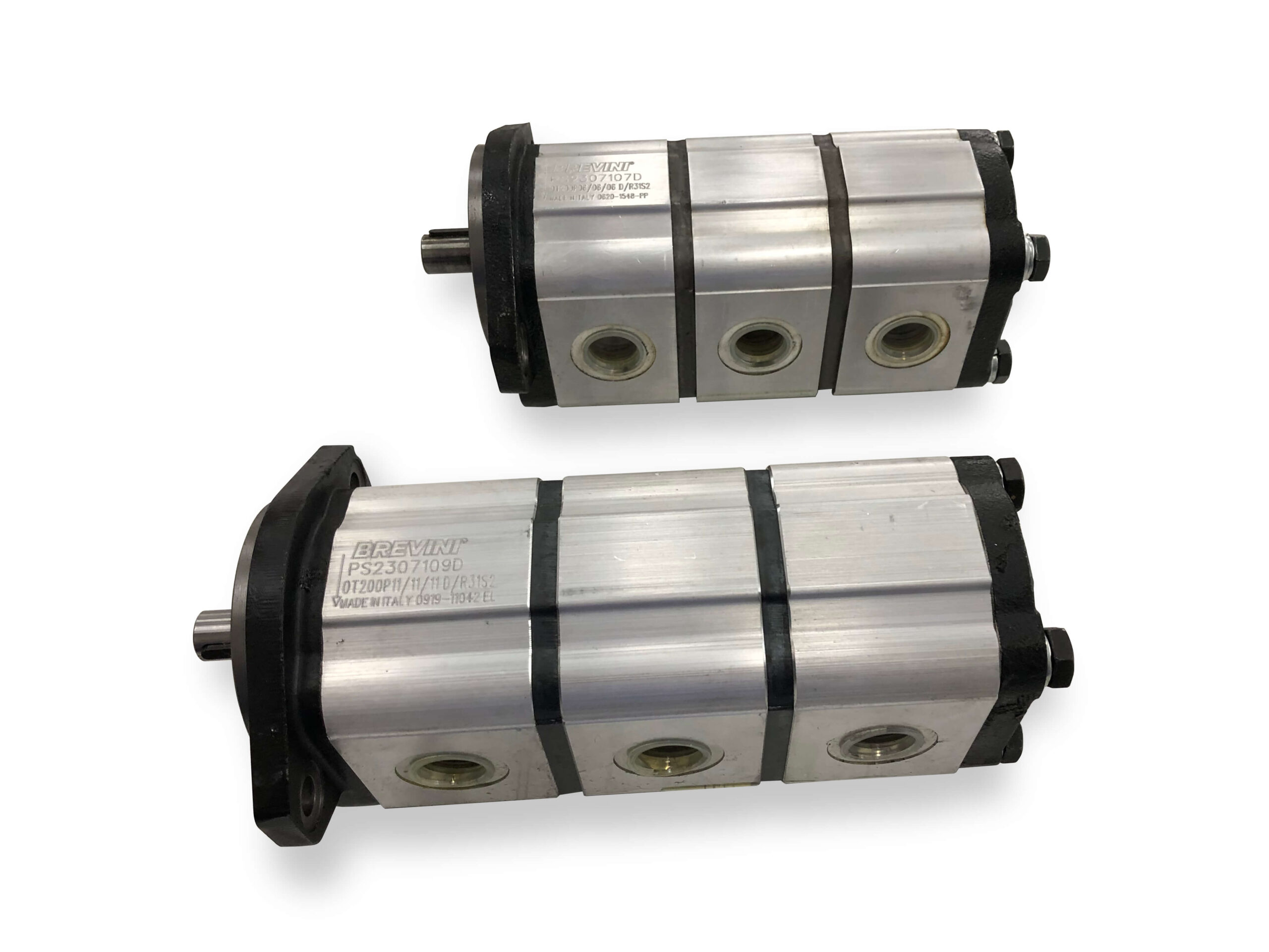
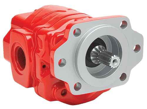
There are typically three types of hydraulic pump constructions found in mobile hydraulic applications. These include gear, piston, and vane; however, there are also clutch pumps, dump pumps, and pumps for refuse vehicles such as dry valve pumps and Muncie Power Products’ Live PakTM.
The hydraulic pump is the component of the hydraulic system that takes mechanical energy and converts it into fluid energy in the form of oil flow. This mechanical energy is taken from what is called the prime mover (a turning force) such as the power take-off or directly from the truck engine.
With each hydraulic pump, the pump will be of either a uni-rotational or bi-rotational design. As its name implies, a uni-rotational pump is designed to operate in one direction of shaft rotation. On the other hand, a bi-rotational pump has the ability to operate in either direction.
For truck-mounted hydraulic systems, the most common design in use is the gear pump. This design is characterized as having fewer moving parts, being easy to service, more tolerant of contamination than other designs and relatively inexpensive. Gear pumps are fixed displacement, also called positive displacement, pumps. This means the same volume of flow is produced with each rotation of the pump’s shaft. Gear pumps are rated in terms of the pump’s maximum pressure rating, cubic inch displacement and maximum input speed limitation.
Generally, gear pumps are used in open center hydraulic systems. Gear pumps trap oil in the areas between the teeth of the pump’s two gears and the body of the pump, transport it around the circumference of the gear cavity and then force it through the outlet port as the gears mesh. Behind the brass alloy thrust plates, or wear plates, a small amount of pressurized oil pushes the plates tightly against the gear ends to improve pump efficiency.
A cylinder block containing pistons that move in and out is housed within a piston pump. It’s the movement of these pistons that draw oil from the supply port and then force it through the outlet. The angle of the swash plate, which the slipper end of the piston rides against, determines the length of the piston’s stroke. While the swash plate remains stationary, the cylinder block, encompassing the pistons, rotates with the pump’s input shaft. The pump displacement is then determined by the total volume of the pump’s cylinders. Fixed and variable displacement designs are both available.
With a fixed displacement piston pump, the swash plate is nonadjustable. Its proportional output flow to input shaft speed is like that of a gear pump and like a gear pump, the fixed displacement piston pump is used within open center hydraulic systems.
As previously mentioned, piston pumps are also used within applications like snow and ice control where it may be desirable to vary system flow without varying engine speed. This is where the variable displacement piston pump comes into play – when the hydraulic flow requirements will vary based on operating conditions. Unlike the fixed displacement design, the swash plate is not fixed and its angle can be adjusted by a pressure signal from the directional valve via a compensator.
Vane pumps were, at one time, commonly used on utility vehicles such as aerial buckets and ladders. Today, the vane pump is not commonly found on these mobile (truck-mounted) hydraulic systems as gear pumps are more widely accepted and available.
Within a vane pump, as the input shaft rotates it causes oil to be picked up between the vanes of the pump which is then transported to the pump’s outlet side. This is similar to how gear pumps work, but there is one set of vanes – versus a pair of gears – on a rotating cartridge in the pump housing. As the area between the vanes decreases on the outlet side and increases on the inlet side of the pump, oil is drawn in through the supply port and expelled through the outlet as the vane cartridge rotates due to the change in area.
Input shaft rotates, causing oil to be picked up between the vanes of the pump which is then transported to pump outlet side as area between vanes decreases on outlet side and increases on inlet side to draw oil through supply port and expel though outlet as vane cartridge rotates
A clutch pump is a small displacement gear pump equipped with a belt-driven, electromagnetic clutch, much like that found on a car’s air conditioner compressor. It is engaged when the operator turns on a switch inside the truck cab. Clutch pumps are frequently used where a transmission power take-off aperture is not provided or is not easily accessible. Common applications include aerial bucket trucks, wreckers and hay spikes. As a general rule clutch pumps cannot be used where pump output flows are in excess of 15 GPM as the engine drive belt is subject to slipping under higher loads.
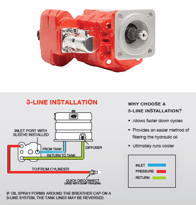
What separates this pump from the traditional gear pump is its built-in pressure relief assembly and an integral three-position, three-way directional control valve. The dump pump is unsuited for continuous-duty applications because of its narrow, internal paths and the subsequent likelihood of excessive heat generation.
Dump pumps are often direct mounted to the power take-off; however, it is vital that the direct-coupled pumps be rigidly supported with an installer-supplied bracket to the transmission case with the pump’s weight at 70 lbs. With a dump pump, either a two- or three-line installation must be selected (two-line and three-line refer to the number of hoses used to plumb the pump); however, a dump pump can easily be converted from a two- to three-line installation. This is accomplished by inserting an inexpensive sleeve into the pump’s inlet port and uncapping the return port.
Many dump bodies can function adequately with a two-line installation if not left operating too long in neutral. When left operating in neutral for too long however, the most common dump pump failure occurs due to high temperatures. To prevent this failure, a three-line installation can be selected – which also provides additional benefits.
Pumps for refuse equipment include both dry valve and Live Pak pumps. Both conserve fuel while in the OFF mode, but have the ability to provide full flow when work is required. While both have designs based on that of standard gear pumps, the dry valve and Like Pak pumps incorporate additional, special valving.
Primarily used on refuse equipment, dry valve pumps are large displacement, front crankshaft-driven pumps. The dry valve pump encompasses a plunger-type valve in the pump inlet port. This special plunger-type valve restricts flow in the OFF mode and allows full flow in the ON mode. As a result, the horsepower draw is lowered, which saves fuel when the hydraulic system is not in use.
In the closed position, the dry valve allows just enough oil to pass through to maintain lubrication of the pump. This oil is then returned to the reservoir through a bleed valve and small return line. A bleed valve that is fully functioning is critical to the life of this type of pump, as pump failure induced by cavitation will result if the bleed valve becomes clogged by contaminates. Muncie Power Products also offer a butterfly-style dry valve, which eliminates the bleed valve requirement and allows for improved system efficiency.
It’s important to note that with the dry valve, wear plates and shaft seals differ from standard gear pumps. Trying to fit a standard gear pump to a dry valve likely will result in premature pump failure.
Encompasses plunger-type valve in the pump inlet port restricting flow in OFF mode, but allows full flow in ON mode lowering horsepower draw to save fuel when not in use
Wear plates and shaft seals differ from standard gear pumps – trying to fit standard gear pump to dry valve likely will result in premature pump failure
Live Pak pumps are also primarily used on refuse equipment and are engine crankshaft driven; however, the inlet on a Live Pak pump is not outfitted with a shut-off valve. With a Live Pak pump, the outlet incorporates a flow limiting valve. This is called a Live Pak valve. The valve acts as an unloading valve in OFF mode and a flow limiting valve in the ON mode. As a result, the hydraulic system speed is limited to keep within safe operating parameters.
Outlet incorporates flow limiting valve called Live Pak valve – acts as an unloading valve in OFF mode and flow limiting valve in ON mode restricting hydraulic system speed to keep within safe operating parameters
Our submersible hydraulic water pump is more versatile and efficient than traditional electric pumps. These portable hydraulic water pumps utilize a highly efficient design to remove water quickly. Moreover, they can run dry and require no cooling while operating.
RGC offers Flow Dividers, allowing you to run RGC tools from an auxiliary power supply. We also offer additional supplies and accessories for our hydraulic water pumps, including hose whips, hydraulic hoses, and biodegradable hydraulic oil.
Questions about our hydraulic water pumps for sale? Reach out to us online by filling out our contact form, or call us at 800-831-5438. With over 75 years of experience in hydraulic tool manufacturing, we’re happy to help in any way we can. Our expert team will answer any questions and provide you with more information regarding our pump products and hydraulic tools.

Facility operators in the oil and gas industry have raised concerns on how to solve their top failure modes: extremely short or non-existent dry run pump time limits and unacceptable levels of cavitation when pumping extremely light liquids with high vapor pressures.
Pump cavitation and dry run related failures cost companies millions of dollars annually, including replacement costs for damaged equipment and lost sales due to poor performance. With an improving economy and anticipated fuel production increase, sales of fluid-handling pumps are forecast to rise 5.5% annually to $84 billion in 2018. Given this proliferation, the historical pattern suggests that costs associated with repairs or replacements also will increase dramatically.
Learn how Parker"s innovation in pump technology can reduce your operational downtime, decrease operating costs, and improve performance. Download our white paper now.
Dry running occurs when a pump operates without sufficient lubricating liquid around the pumping element. This can be caused by either widespread vapor formation, also known as cavitation, inside the pump or absence of pumping fluid altogether. These adverse conditions can lead to dangerously unstable pressure, flow, or overheating which may cause the pumping element to seize or break.
When cavitation occurs, vapor bubbles form and expand in the pumping liquid on the suction side of the pump before reaching the higher-pressure discharge side of the pump and violently collapsing near the surface of the pumping element. This triggers shock waves inside the pump which cause significant damage to the pumping element. If left untreated, cavitation will destroy the pumping element and other components over time, drastically shortening the pump’s life.
Cavitation itself may also be so widespread that it creates a dry run situation inside the pump due to excessive vapor formation. Pumps most often rely on the pumping fluid itself to lubricate the bearing surfaces of the pumping element – if a pump is operated without this fluid, the low to non-existent lubrication at these bearing surfaces will cause excess heat generation, increased wear, and potentially even failure of the pump if the pumping element seizes or breaks. The life of a pump subjected to dry run will be significantly reduced or, in the worst case, brought to an untimely end.
“What separates our solution from our competitors is, our technology is automated and integrated into the pump design. You don’t need to worry about pumps stopping and starting every 20 – 30 seconds, they will dry run continuously.”
Learn how this innovation in pump technology can reduce your operational downtime, decrease operating costs, and improve performance. Download our white paper now.

All John Blue Centrifugal Pumps can run dry without damaging the seal. This, combined with a two-year factory-backed UNCONDITIONAL WARRANTY on cast-iron models, makes the John Blue Centrifugal Pumps second to no other pump manufacturer on the market today — all at an affordable price. Our centrifugal pumps are available with gas, electric, or hydraulic power sources.


 8613371530291