
running hydraulic pump dry supplier
Dry lift pumping applications often require lifting a fluid from below the level of the pump. This is generally not a problem for a positive displacement pump that is primed with fluid. However, getting the pump to self-prime depends not only on the characteristics of the pump, but also on the design of the system and the operating conditions. To understand better the application of a pump required to self-prime, let"s discuss some pump fundamentals and good design practices.
Self-priming with a liquid level below the pump requires lifting the fluid. This means that the pump has to develop enough negative pressure (or vacuum) to pull the fluid up the inlet line into the pump. It is important to note that Micropump® products operate very well under high vacuum fluid conditions. However, when a pump is attempting to prime without fluid inside the pump, it is essentially pumping air. Although Micropump gear pumps are intended for use as fluid pumps, they are able to move air because the internal clearances are relatively small.
The amount of air that a pump is able to move depends on the system design, the type of pump, the amount of internal clearance, how well the internal clearances are sealed, the speed of operation, and the characteristics of the fluid to be pumped.
The first thing to consider in a self-priming application is whether or not it is absolutely necessary to make the pump perform this function. It is always good design practice to avoid making the pump dry lift. A flooded inlet is best. However, if it is necessary for the pump to dry lift, it is recommended that the lift elevation be kept to a minimum.
In some cases a flooded inlet is not enough. Pumping out of a condenser or evacuated reservoir may require additional energy to get the fluid into the pump. It may be necessary to raise the reservoir up 10 meters (30 feet), or more, to provide the necessary inlet pressure needed to fill the pump.
The outlet condition of the pump will also affect the ability of the pump to self-prime. If the pump outlet is blocked or restricted, the air being evacuated from the inlet side has nowhere to go except to leak back through the internal clearances of the pump, and the vacuum created will be considerably reduced.
The type of pump is the next consideration in a self-prime application. Micropump manufactures two types of positive displacement gear pumps: a conventional cavity style and a suction shoe design. In general, the conventional cavity style, such as the Series GJ, is preferred. This series has a fixed cavity with small internal clearances, which make its sealing capabilities very good.
There are three gear materials available in the cavity design: PTFE, Ryton and PEEK. PTFE gears have a relatively high coefficient of thermal expansion compared with stainless steel. This means that if the pump is run dry for an extended period, the gears will heat up and try to expand beyond their internal clearances. This will generally decouple the pump and wear the tips of the gears in the process. This will reduce the volumetric efficiency of the pump, as well as its ability to self-prime.
If PTFE gears are not required, consider Ryton or PEEK gears. These materials have better wear characteristics than PTFE and can be run dry for a longer period of time without damage. Micropump recommends that our pumps never be run dry; however, we have heard claims of pumps with Ryton gears accidentally being run dry for extended periods, and then restarted with fluid, showing no significant loss in performance.
The second type of positive displacement gear pump manufactured by Micropump is the “Suction Shoe” design. In this design, the gears are sealed by a floating “shoe” that is pressure loaded by the differential pressure developed by the pump. In addition, there are two types of suction shoe pumps available: one with graphite components and the other with Ryton or PEEK.
The Series GA pumps use carbon graphite gears (X21, V21, and V23) and suction shoes that are machined to very close tolerances. This low displacement, high precision pump has very small internal clearances and uses a bias spring to physically hold the suction shoe against the gears when self-priming. In this case, these features prevail over the inherent self-priming problems in this design. The design gives the Series GA pumps have very good self-priming characteristics.
In most cases, moisture will improve the sealing of the internal clearances. All Micropump pumps are tested before shipment so they will generally have some fluid left inside. However, if it is possible to wet the gears before starting, the self-priming capability of the pump will significantly improve.
Speed of operation is also important in self-priming. In general, a small displacement pump running at a higher speed will lift better than a larger displacement pump at a lower speed. However, this relationship is not proportional.
There are several types of fluid that are difficult to lift regardless of the pump and system. These include volatile, or low-viscosity fluids, or fluids at high temperature, which can reach their vapor pressure in the inlet line before reaching the pump. Fluids with specific gravities higher than water require higher vacuum to lift the same distance. Also, fluids with high viscosities need more vacuum to overcome viscous drag in the inlet line.
It must be noted that when pumping volatile fluids, such as from a barrel, the fluid path should always be grounded. It is possible for static discharge to occur and cause a spark or fire.
In conclusion, applications requiring a pump to self-prime can be successful if the proper pump design and drive are selected, the properties of the fluid are considered, and good design practices are followed. The pump selection should consider materials and self-priming capability, as well as operating performance. The system should be designed so that lift elevation is minimized and the outlet of the pump is not restricted.

Dry running a pump can cause all kinds of serious problems, yet many operators are unaware of the dangers. When a pump runs dry, it generates heat and force it was never designed to handle, leading to wear and tear that can quickly add up to inflated repair costs. Avoiding dry running is highly important, but it makes sense to learn how negative it can be in order to fully understand the severity of the phenomenon.
When a pump runs dry, it runs without any liquid going through it. This is always a bad idea, as it puts an inordinate amount of strain on the pump’s moving parts.
Instead of circulating fluid, a dry running pump pushes nothing but air around, leading to friction, heat, and destruction of delicate internals. A hydraulic pump is normally designed to run while filled with fluid. As it runs, the fluid inside it helps to preserve its internal pieces, cooling them and even assisting in centreing moving elements such as the rotor.
Pumps that operate at particularly high pressure can suffer considerable cavitation simply from fluid-derived vapor; completely dry running a finely tuned pump is significantly worse for its longevity. Even self-priming pumps should only be run once the proper amount of fluid is inside, as they can withstand only partial dry conditions while priming themselves.
Running your hydraulic pump dry is likely to result in disaster, wearing it out prematurely via the aforementioned heat, violent vibrations, or complete lock-up/seizure of important parts, costing you money to fix or replace.
Running a hydraulic pump dry can lead to a large variety of issues with the pump’s parts and the rest of your hydraulic system as well. Here are a few common problems that dry running can cause:
High temperatures caused by dry running can ruin your pump, pitting its housing and causing leaks.¹ If heat and pressure are excessive enough, the housing boss may deform, potentially stopping your impeller from rotating freely and rendering your pump functionally useless. In many cases, a severely damaged, leaking pump is likely to need replacing, which can run your costs up much further than anticipated.
As is the case for the housing of your pump, the impeller is susceptible to damage done by excessive heat during use. Dry running your pump causes friction, and this friction is strong enough to heat up the impeller, causing it to melt.² Even minor melting is severely detrimental to your pump’s performance, potentially causing it to seize up and stop working at all. Taking it apart for repair is usually an involved and costly exercise best avoided through preventive operating practices.
Internal wear caused by dry running your pump can lead to additional wear throughout the entirety of your system. This is generally caused by either excessive heat or metal particles scraped from disintegrating moving pieces within your pump travelling through the rest of your system. Metal particles, in particular, can cut and clog valve components, pipes, and tubes, leading to system failure over time.
You may need to run your pump dry for short periods of time to empty the system completely, but it is best to keep such instances as brief as possible. Once your tank or system has been emptied by the pump, it should be turned off. Do not allow it to keep running for more than a minute without any fluid.
Keeping someone in charge of monitoring your pump as it runs can help avoid unintended dry running problems. Often, a pump may be left running until a job is completed. If the pump performs its function faster than intended and all fluid is purged from the system, it will run dry and damage itself until an operator returns to turn it off. Having someone manage the pump at all times is crucial to keeping it functional.
Some companies have found an automatic means of controlling their pumps’ functions from afar. By leveraging special protective devices and control systems, it is possible to automatically stop a pump that is in danger of running dry, preserving its internal parts and averting expensive disasters.³ However, such devices incur an additional cost.
At White House Products, Ltd., we offer all manner ofpump parts to patch up a system damaged by dry running. We can also provide complete replacements as needed. Call our technical support team at +44 (0)1475 742500 to learn how we can help get your pump working again.

Ace developed the first hydraulic motor driven pump at the request of John Deere in 1969. Many of the original pumps are still operating today after more than 30 years of service.
Centrifugal pump design provides good resistance to abrasive solutions and extra flow for agitation. The advantages of the hydraulic motor driven pump are mounting versatility, customized performance, and ease of maintenance. All hydraulic driven pumps are equipped with a stainless steel shaft and wear ring for excellent corrosion resistance.MOUNTING VERSATILITY:The location of the pump is not tied to the PTO or engine drive shaft; the pump can be mounted in a variety of locations to suit application requirements.
CUSTOMIZED PERFORMANCE: The performance is dependent on the supply of hydraulic oil to the motor and not necessarily tied to engine speed. A hydraulic driven pump can produce higher pressures than PTO or belt driven pumps. They can also hold constant pressure at varying engine speeds on closed center hydraulic systems.
EASY MAINTENANCE: On a hydraulic driven pump there are no belts to align or break. Separate pump and hydraulic motor shafts simplify repair and replacement. Two main pump bearings support shaft loads. All pumps are equipped with easily replaceable FKM mechanical seals.
The Ace gear type hydraulic motor is more efficient than gerotor type motors, and is less subject to damage by contamination than the gerotor design. A built-in needle valve allows for the bypass of up to 9 GPM excess hydraulic fluid on open center systems. The standard motor has a reverse flow check valve which prevents backward hookup and a coasting check which protects the motor seal from the flywheel effect of the impeller. A restrictor orifice is included with pump models recommended for pressure compensating closed center systems. The Ace Internet Hydraulic Selection Guide is here to help in finding the proper hydraulic pump for your tractor.
The 206 motor requires 7 GPM (26.5 LPM) maximum hydraulic fluid input and fits virtually all tractor hydraulic systems. Recommended for:Pressure Compensating Closed Center Systems
The 206 motor requires 7 GPM (26.5 LPM) maximum hydraulic fluid input and fits virtually all tractor hydraulic systems. Recommended for:Pressure Compensating Closed Center Systems
The 310 motor requires 16 GPM (60.6 LPM) maximum hydraulic fluid input. Recommended for:Large Open Center Systems up to 24 GPM (90.9 LPM) using internal needle valve bypass.
The 206 motor requires 7 GPM (26.5 LPM) maximum hydraulic fluid input and fits virtually all tractor hydraulic systems. Recommended for:Pressure Compensating Closed Center Systems
The 206 motor requires 7 GPM (26.5 LPM) maximum hydraulic fluid input and fits virtually all tractor hydraulic systems. Recommended for:Pressure Compensating Closed Center Systems
The 206 motor requires 7 GPM (26.5 LPM) maximum hydraulic fluid input and fits virtually all tractor hydraulic systems. Recommended for:Pressure Compensating Closed Center Systems
The 206 motor requires 7 GPM (26.5 LPM) maximum hydraulic fluid input and fits virtually all tractor hydraulic systems. Recommended for:Pressure Compensating Closed Center Systems
The Gemini DPK (Dual Pump Kit) was designed to solve these concerns. Pick any two pumps with 204 or 206 motors, and run them from one SCV remote port. Run them at different rates. Shut one pump off while leaving the other pump running. Have your rate controller send PWM signal to one or both of the pumps for precision application.
The 310 motor requires 16 GPM (60.6 LPM) maximum hydraulic fluid input. Recommended for:Large Open Center Systems up to 24 GPM (90.9 LPM) using internal needle valve bypass.
Severe duty silicon carbide seal standard - resists abrasive scratching and transfers heat away from seal faces for improved survival during short run-dry events
The 206 motor requires 7 GPM (26.5 LPM) maximum hydraulic fluid input and fits virtually all tractor hydraulic systems. Recommended for:Pressure Compensating Closed Center Systems
The 206 motor requires 7 GPM (26.5 LPM) maximum hydraulic fluid input and fits virtually all tractor hydraulic systems.Pressure Compensating Closed Center Systems
Severe duty silicon carbide seal standard - resists abrasive scratching and transfers heat away from seal faces for improved survival during short run-dry events
The 206 motor requires 7 GPM (26.5 LPM) maximum hydraulic fluid input and fits virtually all tractor hydraulic systems.Pressure Compensating Closed Center Systems
The 206 motor requires 7 GPM (26.5 LPM) maximum hydraulic fluid input and fits virtually all tractor hydraulic systems.Pressure Compensating Closed Center Systems

Capable of higher flows and pressures than GA Series pumps, GR Series pumps provide high efficiency, pulse-free pumping, even under the most challenging conditions. They are designed ...
The Warman® SHW sump pump is a customisable sump pumping solution that offers advanced pump features for a variety of solids handling requirements. The SHW pump makes extensive use of ...
The VN Family of pumps is designed for the ultimate flexibility in slurry handling applications. The vertical cantilever design eliminates submerged beargings, top suction design eliminates air binding, which allows the ...
Premium design white cast iron pump for long service life handling severe slurries. The maintenance-friendly single-wall construction and heavy section white cast iron wet end combined with the cartridge bearing assembly ...
... 1” non-metallic diaphragm pumps are a versatile solution for numerous applications. Our EXP 1” models achieve flow rates of up to 53 GPM (200.6 LPM) and offer a wide array of material and porting configurations. These ...
Metering pumps of the CHEM series are made of corrosion-resistant stainless steel. For the delivery of Adblue® a variety of sealing systems and a wide range of modular materials are available for this series. Due to their ...
The DPA 0105 is a DC pump manufactured by Nitto. The pump can operate continuously on a 12V or 24V rated voltage for 5.000h. Weighing at 0.3kg, it is capable of delivering a maximum pressure of 2.2bar ...
The TORNADO® T.Sano® rotary lobe pump in all-metal design is the optimum solution for your applications in the hygiene sector due to its oil and dead space free design. It is also easy ...
... interface within the pump. Elastomer to elastomer component surface interfaces, which suffer from excess wear and generate heat, are eliminated. This makes TORNADO® rotary lobe pumps particularly robust ...
... the pump cover, you can easily position the rotary lobes after servicing without the need for expensive special tools. Both the all-metal and the industrial models deliver continuously and evenly. The oil-free ...
... heavy-duty type TPC-M vertical cantilever pump without bottom bearing is designed with run-dry capabilities to pump solids-carrying acids, alkalis and chemically contaminated effluents directly from pump ...
... heavy-duty type TPC vertical cantilever pump without bottom bearing is designed with run-dry capabilities to pump solids-carrying acids, alkalis and chemically contaminated effluents directly from pump ...
... cantilever pump without bottom bearing is designed with run-dry capabilities to pump solids-carrying acids, alkalis and chemically contaminated effluents directly from pump sumps, pump ...
... durability, safety and product containment. The result is a pump that delivers very high suction and discharge pressures that allow it to self-prime and fully maximize product containment. SLC Series pumps ...
Submersible pump with semi-open impeller with cast iron shim and anti-clogging filters, supplied as standard with the thermal protector and double mechanical seal with oil chamber. Suitable for pumping ...
CUBIC 15 diaphragm pumps are characterized by exceptional performance, power and strength, making them ideal for pumping liquids with high apparent viscosity even if containing suspended solids. Especially suitable in ...
MIDGETBOX diaphragm pumps are characterized by exceptional performance, power and strength, making them ideal for pumping liquids with high apparent viscosity even if containing suspended solids. Especially suitable in ...
BOXER 15 diaphragm pumps are characterized by exceptional performance, power and strength, making them ideal for pumping liquids with high apparent viscosity even if containing suspended solids.
The TopAir series is one of the most complete lines of Air Operated Double Diaphragm pumps on the market. With eight sizes up to 800 l/min in a wide range of material ...
Versa-Matic"s E1 1" pump uses the Elima-Matic air valve system to provide non-stalling, lube-free performance. The E1 1" plastic bolted pump comes in optional and standard porting models, ...
Our submersible hydraulic water pump is more versatile and efficient than traditional electric pumps. These portable hydraulic water pumps utilize a highly efficient design to remove water quickly. Moreover, they can run dry and require no cooling while operating.
RGC offers Flow Dividers, allowing you to run RGC tools from an auxiliary power supply. We also offer additional supplies and accessories for our hydraulic water pumps, including hose whips, hydraulic hoses, and biodegradable hydraulic oil.
Questions about our hydraulic water pumps for sale? Reach out to us online by filling out our contact form, or call us at 800-831-5438. With over 75 years of experience in hydraulic tool manufacturing, we’re happy to help in any way we can. Our expert team will answer any questions and provide you with more information regarding our pump products and hydraulic tools.
Anyone familiar with industrial magnetic drive (mag drive) pumps has been asked about dry running the pump. After all, a dishwasher and washing machine at home does that all the time. There are bearing materials that allow that, right? Sure, a qualified “yes,” but it is time to take a closer look at dry running.
Dry running, except in the literal sense, is a misnomer. Industrial pumps are mechanically sealed or sealless and can suffer from the results of what the industry has dubbed “dry run operation.” This article will focus on the mag drive pump configuration with silicon carbide (SiC) bearing components, which is one of the two sealless types of rotodynamic centrifugal pumps.
Mag drive pumps have product-lubricated bearings that require liquid to be present for proper operation. These hydrodynamic (plain) bearings depend on a fluid barrier separating the bearing components that becomes a wedge when there is relative motion between the two surfaces. When this fluid barrier is disrupted, the two surfaces will touch and can lead to component damage. This effect can be cumulative, resulting in component failure when limits are reached.
If the SiC surfaces touch during operation, the components can break in a short time (depending on several factors). This does not mean the pump stops operating immediately. The broken SiC pieces may still support the shaft well enough to allow rotation of the pump rotor. Broken SiC can be detected by increased vibration and often a power increase. The condition of the pump will only get worse if operation is continued.
When the pump loses suction, it should be shut down immediately. Damage to the SiC components can occur in a matter of seconds. Using a power monitor to detect when the motor load has suddenly changed, such as when the pump loses suction, will protect major pump components. Continued operation without adequate liquid at the suction can quickly lead to severe damage of the SiC components.
For long life, the pump requires only that there be liquid available, operation within the pump flow range of the curve, and within the pump design limits. Please note that it is best to start the pump against a partially closed (about a quarter open) discharge valve. The suction valve should always be open when operating and only closed when the pump must be isolated for maintenance reasons.
excessive temperature that causes pumped liquid (lubricating flow) to vaporize at the bearing component surfaces—or not enough internal system pressure to keep the pumped fluid in liquid state as it passes through the pump
Specially treated sintered SiC is available from a number of suppliers to provide enhanced dry-running capabilities in the case of a system upset condition. Some manufacturers use coatings that adhere to the substrate SiC, while others use infusion methods that mechanically integrate the coating into the base material. All of these are called diamond-like coatings (DLC) in the industry. These treatments substantially reduce the surface coefficient of friction compared to that of standard sintered SiC. Less friction during system upset and other dry run conditions generate less heat, reducing the potential for bearing component breakage from mechanical contact or thermal shock.
In reference to pumping equipment and product lubricated bearings, no one recommends that the pump be operated without liquid passing through it. There is some residual liquid that remains when the unit loses suction, but that will quickly be pressed out of the sides of the bearing components with continued operation. Vaporization of the liquid can occur quickly, depending on the size of the pump.
Definitive dry run times would require specific testing of the pump size and conditions of service in question. For small pumps under 2 horsepower (hp), testing has shown that the dry run time is minutes and can be stretched to more than an hour for the smallest pumps with the DLC coated bearings. The greater the power input to the pump, the shorter the time period before damage occurs in the bearing system. For larger pumps in the 50-plus-hp range, while DLC coatings will still help, the time before damage occurs remains quite short. Energizing the motor to check rotation of a pump without DLC coated bearings or liquid in the unit will likely result in some bearing damage. Damage from dry running will initially appear as cracked or chipped SiC components. As the liquid vanishes and the rotating ceramic components come in contact with stationary components, the SiC can shatter, breaking into small pieces. Continued operation damages more pump components such as the shaft, rear casing, casing cover and impeller—all of which are costly parts. This type of damage to the pump is preventable.
Again, it is recommended that the pump be protected by a power monitor and that the low power trip point be set at a level representing the first indication that suction has been lost. Setting the low trip point time delay at less than 2 to 3 seconds can prevent tripping of the pump when a large bubble of vapor/air vents through the pump without losing suction. Trying to run longer to empty the suction line of product will result in damage to the pump that is more costly than the small amount of product that may remain in the suction line. A properly set power monitor will save money for the pump owner in several enterprise accounts.
Lined, mag drive pumps use either SiC or nonmetallic bearing materials. Some of the latter may have enhanced lubricity but are still subject to the same axioms of running with compromised lubrication.
Canned motor pumps, the other sealless centrifugal type, typically use softer bearing materials including carbon that are more lubricious, but susceptible to wear. These require a bearing monitor system to avoid component damage.
With mechanically sealed pumps, seal faces operate on a similar hydrodynamic film and require the same type of lubrication. They will not run dry long without damage either.

Dry Running is an undesirable condition which affects most pump designs and is characterised when a pump operates without an adequate amount of fluid. In most pump technologies, this leads to cavitation and critical damage to the internal pumping elements such as impellers, lobes, gears, casings, seals & bearings.
Dry running is usually related to how the pump is operated, monitored & controlled which is typically a result of human error. Companies generally rely on their operators to monitor the pumps on the line, however, problems will arise when a pump is unintentionally left running for prolonged periods of time after the intended operation has been completed. For example, during offloading of a tanker, an operator may leave the pump unattended whilst the tanker is being evacuated and the pump may over-run when the tanker is empty thus resulting in damage to the pump internals.
Dry running could lead mechanical seals to wearing quickly which could cause the pump to leak. This will allow the potentially hazardous liquid to spill putting pump operators at risk.
Dry running can damage your pump which could cause an immediate stop to your production line meaning a loss of production – delays & costs to your business
Risked cavitation if dry run for long periods of time which may require the whole pump to be replaced if there has been serious damage to the impellers in your pump
Dry Running can be extremely costly to your business so please check with your supplier or the pump manufacturer whether the pump you’ve purchased can be dry run before operating it.
When using most pump designs, such as Rotodynamic as well as Reciprocating and Rotary Positive Displacement Pumps, most companies need to install protection and control devises on the pumps and system to ensure that the pump is stopped immediately after the pumping operation is complete, or in the absence of fluid at the pump suction or source.
Pressure or Level Switch Protection:Pressure Switches fitted to the suction pipe or port of the pump(s) or Float Switches/Electrode Relays in the Supply tank
Engineers on-site and Operators spend significant amounts of time ensuring pumps are properly installed & primed, significantly increasing the cost and complexity of the installation. However, despite all these efforts, the ever-present possibility of human error, malfunctioning control and monitoring equipment, unpredictable events & improper use of equipment means that Dry Running is never completely eradicated. As a result, plant owners are constantly in search of technology and solutions which can prevent or avoid the costly and damaging effects of Dry Running in order to reduce maintenance costs, increase throughput and alleviate pressures put onto operators to constantly monitor, control and protect their equipment on the line.
There are a variety of standard accessories that can be used to control pumping equipment to protect is from dry running such as pressure and temperature sensors. Additional accessories and expensive sealing systems aren’t always the answer. Not all pumps are created equally, in fact, at Tapflo UK we have a variety of pump solutions that will allow you to dry run your pump without causing damage to it. Need your pump to run dry? Let us know when you call us.
Tapflo offer a range of pump technologies that have the added benefit of being able to dry run, including our Diaphragm Pumps and Peristaltic Pumps which can run dry indefinitely without damaging the pump.
Due to their design and construction, both of these pumping technologies are able to operate under dry conditions without experiencing common wear problems associated with dry running. Not only does this alleviate the pressure put on the operator, but it also simplifies the pumping system and reduces the cost of installation and ownership significantly. Of course, these designs, on their own, do not overcome the energy costs affiliated with overrunning equipment, to improve this, Tapflo offers dry run protection devices such as our Pneumatic Guardian System for Diaphragm Pumps which automatically stops your pump when the pumping process is complete.
In summary, Tapflo UK have a full range of pumping solutions which can either protect equipment from Dry Running or indeed avoid problems associated with Dry Running completely! Let’s discuss your options today.
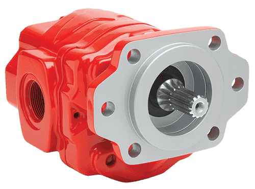
There are typically three types of hydraulic pump constructions found in mobile hydraulic applications. These include gear, piston, and vane; however, there are also clutch pumps, dump pumps, and pumps for refuse vehicles such as dry valve pumps and Muncie Power Products’ Live PakTM.
The hydraulic pump is the component of the hydraulic system that takes mechanical energy and converts it into fluid energy in the form of oil flow. This mechanical energy is taken from what is called the prime mover (a turning force) such as the power take-off or directly from the truck engine.
With each hydraulic pump, the pump will be of either a uni-rotational or bi-rotational design. As its name implies, a uni-rotational pump is designed to operate in one direction of shaft rotation. On the other hand, a bi-rotational pump has the ability to operate in either direction.
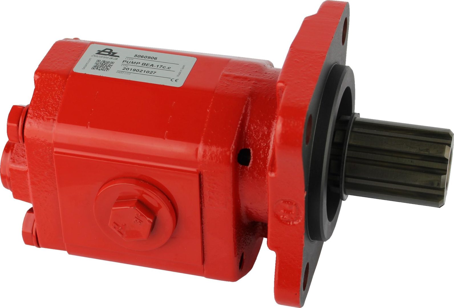
For truck-mounted hydraulic systems, the most common design in use is the gear pump. This design is characterized as having fewer moving parts, being easy to service, more tolerant of contamination than other designs and relatively inexpensive. Gear pumps are fixed displacement, also called positive displacement, pumps. This means the same volume of flow is produced with each rotation of the pump’s shaft. Gear pumps are rated in terms of the pump’s maximum pressure rating, cubic inch displacement and maximum input speed limitation.
Generally, gear pumps are used in open center hydraulic systems. Gear pumps trap oil in the areas between the teeth of the pump’s two gears and the body of the pump, transport it around the circumference of the gear cavity and then force it through the outlet port as the gears mesh. Behind the brass alloy thrust plates, or wear plates, a small amount of pressurized oil pushes the plates tightly against the gear ends to improve pump efficiency.
A cylinder block containing pistons that move in and out is housed within a piston pump. It’s the movement of these pistons that draw oil from the supply port and then force it through the outlet. The angle of the swash plate, which the slipper end of the piston rides against, determines the length of the piston’s stroke. While the swash plate remains stationary, the cylinder block, encompassing the pistons, rotates with the pump’s input shaft. The pump displacement is then determined by the total volume of the pump’s cylinders. Fixed and variable displacement designs are both available.
With a fixed displacement piston pump, the swash plate is nonadjustable. Its proportional output flow to input shaft speed is like that of a gear pump and like a gear pump, the fixed displacement piston pump is used within open center hydraulic systems.
As previously mentioned, piston pumps are also used within applications like snow and ice control where it may be desirable to vary system flow without varying engine speed. This is where the variable displacement piston pump comes into play – when the hydraulic flow requirements will vary based on operating conditions. Unlike the fixed displacement design, the swash plate is not fixed and its angle can be adjusted by a pressure signal from the directional valve via a compensator.
Vane pumps were, at one time, commonly used on utility vehicles such as aerial buckets and ladders. Today, the vane pump is not commonly found on these mobile (truck-mounted) hydraulic systems as gear pumps are more widely accepted and available.
Within a vane pump, as the input shaft rotates it causes oil to be picked up between the vanes of the pump which is then transported to the pump’s outlet side. This is similar to how gear pumps work, but there is one set of vanes – versus a pair of gears – on a rotating cartridge in the pump housing. As the area between the vanes decreases on the outlet side and increases on the inlet side of the pump, oil is drawn in through the supply port and expelled through the outlet as the vane cartridge rotates due to the change in area.
Input shaft rotates, causing oil to be picked up between the vanes of the pump which is then transported to pump outlet side as area between vanes decreases on outlet side and increases on inlet side to draw oil through supply port and expel though outlet as vane cartridge rotates
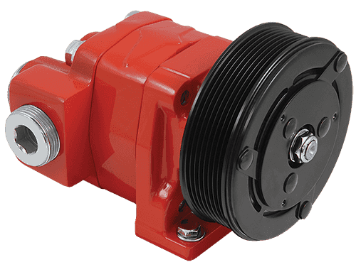
A clutch pump is a small displacement gear pump equipped with a belt-driven, electromagnetic clutch, much like that found on a car’s air conditioner compressor. It is engaged when the operator turns on a switch inside the truck cab. Clutch pumps are frequently used where a transmission power take-off aperture is not provided or is not easily accessible. Common applications include aerial bucket trucks, wreckers and hay spikes. As a general rule clutch pumps cannot be used where pump output flows are in excess of 15 GPM as the engine drive belt is subject to slipping under higher loads.
What separates this pump from the traditional gear pump is its built-in pressure relief assembly and an integral three-position, three-way directional control valve. The dump pump is unsuited for continuous-duty applications because of its narrow, internal paths and the subsequent likelihood of excessive heat generation.
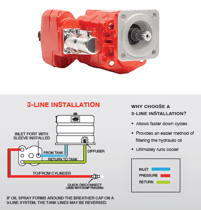
Dump pumps are often direct mounted to the power take-off; however, it is vital that the direct-coupled pumps be rigidly supported with an installer-supplied bracket to the transmission case with the pump’s weight at 70 lbs. With a dump pump, either a two- or three-line installation must be selected (two-line and three-line refer to the number of hoses used to plumb the pump); however, a dump pump can easily be converted from a two- to three-line installation. This is accomplished by inserting an inexpensive sleeve into the pump’s inlet port and uncapping the return port.
Many dump bodies can function adequately with a two-line installation if not left operating too long in neutral. When left operating in neutral for too long however, the most common dump pump failure occurs due to high temperatures. To prevent this failure, a three-line installation can be selected – which also provides additional benefits.
Pumps for refuse equipment include both dry valve and Live Pak pumps. Both conserve fuel while in the OFF mode, but have the ability to provide full flow when work is required. While both have designs based on that of standard gear pumps, the dry valve and Like Pak pumps incorporate additional, special valving.
Primarily used on refuse equipment, dry valve pumps are large displacement, front crankshaft-driven pumps. The dry valve pump encompasses a plunger-type valve in the pump inlet port. This special plunger-type valve restricts flow in the OFF mode and allows full flow in the ON mode. As a result, the horsepower draw is lowered, which saves fuel when the hydraulic system is not in use.
In the closed position, the dry valve allows just enough oil to pass through to maintain lubrication of the pump. This oil is then returned to the reservoir through a bleed valve and small return line. A bleed valve that is fully functioning is critical to the life of this type of pump, as pump failure induced by cavitation will result if the bleed valve becomes clogged by contaminates. Muncie Power Products also offer a butterfly-style dry valve, which eliminates the bleed valve requirement and allows for improved system efficiency.
It’s important to note that with the dry valve, wear plates and shaft seals differ from standard gear pumps. Trying to fit a standard gear pump to a dry valve likely will result in premature pump failure.
Encompasses plunger-type valve in the pump inlet port restricting flow in OFF mode, but allows full flow in ON mode lowering horsepower draw to save fuel when not in use
Wear plates and shaft seals differ from standard gear pumps – trying to fit standard gear pump to dry valve likely will result in premature pump failure
Live Pak pumps are also primarily used on refuse equipment and are engine crankshaft driven; however, the inlet on a Live Pak pump is not outfitted with a shut-off valve. With a Live Pak pump, the outlet incorporates a flow limiting valve. This is called a Live Pak valve. The valve acts as an unloading valve in OFF mode and a flow limiting valve in the ON mode. As a result, the hydraulic system speed is limited to keep within safe operating parameters.
Outlet incorporates flow limiting valve called Live Pak valve – acts as an unloading valve in OFF mode and flow limiting valve in ON mode restricting hydraulic system speed to keep within safe operating parameters

A gear pump is a type of positive displacement (PD) pump. It moves a fluid by repeatedly enclosing a fixed volume using interlocking cogs or gears, transferring it mechanically using a cyclic pumping action. It delivers a smooth pulse-free flow proportional to the rotational speed of its gears.
Gear pumps use the actions of rotating cogs or gears to transfer fluids. The rotating element develops a liquid seal with the pump casing and creates suction at the pump inlet. Fluid, drawn into the pump, is enclosed within the cavities of its rotating gears and transferred to the discharge. There are two basic designs of gear pump: external and internal(Figure 1).
An external gear pump consists of two identical, interlocking gears supported by separate shafts. Generally, one gear is driven by a motor and this drives the other gear (the idler). In some cases, both shafts may be driven by motors. The shafts are supported by bearings on each side of the casing.
As the gears come out of mesh on the inlet side of the pump, they create an expanded volume. Liquid flows into the cavities and is trapped by the gear teeth as the gears continue to rotate against the pump casing.
No fluid is transferred back through the centre, between the gears, because they are interlocked. Close tolerances between the gears and the casing allow the pump to develop suction at the inlet and prevent fluid from leaking back from the discharge side (although leakage is more likely with low viscosity liquids).
An internal gear pump operates on the same principle but the two interlocking gears are of different sizes with one rotating inside the other. The larger gear (the rotor) is an internal gear i.e. it has the teeth projecting on the inside. Within this is a smaller external gear (the idler –only the rotor is driven) mounted off-centre. This is designed to interlock with the rotor such that the gear teeth engage at one point. A pinion and bushing attached to the pump casing holds the idler in position. A fixed crescent-shaped partition or spacer fills the void created by the off-centre mounting position of the idler and acts as a seal between the inlet and outlet ports.
As the gears come out of mesh on the inlet side of the pump, they create an expanded volume. Liquid flows into the cavities and is trapped by the gear teeth as the gears continue to rotate against the pump casing and partition.
Gear pumps are compact and simple with a limited number of moving parts. They are unable to match the pressure generated by reciprocating pumps or the flow rates of centrifugal pumps but offer higher pressures and throughputs than vane or lobe pumps. Gear pumps are particularly suited for pumping oils and other high viscosity fluids.
Of the two designs, external gear pumps are capable of sustaining higher pressures (up to 3000 psi) and flow rates because of the more rigid shaft support and closer tolerances. Internal gear pumps have better suction capabilities and are suited to high viscosity fluids, although they have a useful operating range from 1cP to over 1,000,000cP. Since output is directly proportional to rotational speed, gear pumps are commonly used for metering and blending operations. Gear pumps can be engineered to handle aggressive liquids. While they are commonly made from cast iron or stainless steel, new alloys and composites allow the pumps to handle corrosive liquids such as sulphuric acid, sodium hypochlorite, ferric chloride and sodium hydroxide.
External gear pumps can also be used in hydraulic power applications, typically in vehicles, lifting machinery and mobile plant equipment. Driving a gear pump in reverse, using oil pumped from elsewhere in a system (normally by a tandem pump in the engine), creates a hydraulic motor. This is particularly useful to provide power in areas where electrical equipment is bulky, costly or inconvenient. Tractors, for example, rely on engine-driven external gear pumps to power their services.
Gear pumps are self-priming and can dry-lift although their priming characteristics improve if the gears are wetted. The gears need to be lubricated by the pumped fluid and should not be run dry for prolonged periods. Some gear pump designs can be run in either direction so the same pump can be used to load and unload a vessel, for example.
The close tolerances between the gears and casing mean that these types of pump are susceptible to wear particularly when used with abrasive fluids or feeds containing entrained solids. However, some designs of gear pumps, particularly internal variants, allow the handling of solids. External gear pumps have four bearings in the pumped medium, and tight tolerances, so are less suited to handling abrasive fluids. Internal gear pumps are more robust having only one bearing (sometimes two) running in the fluid. A gear pump should always have a strainer installed on the suction side to protect it from large, potentially damaging, solids.
Generally, if the pump is expected to handle abrasive solids it is advisable to select a pump with a higher capacity so it can be operated at lower speeds to reduce wear. However, it should be borne in mind that the volumetric efficiency of a gear pump is reduced at lower speeds and flow rates. A gear pump should not be operated too far from its recommended speed.
For high temperature applications, it is important to ensure that the operating temperature range is compatible with the pump specification. Thermal expansion of the casing and gears reduces clearances within a pump and this can also lead to increased wear, and in extreme cases, pump failure.
Despite the best precautions, gear pumps generally succumb to wear of the gears, casing and bearings over time. As clearances increase, there is a gradual reduction in efficiency and increase in flow slip: leakage of the pumped fluid from the discharge back to the suction side. Flow slip is proportional to the cube of the clearance between the cog teeth and casing so, in practice, wear has a small effect until a critical point is reached, from which performance degrades rapidly.
Gear pumps continue to pump against a back pressure and, if subjected to a downstream blockage will continue to pressurise the system until the pump, pipework or other equipment fails. Although most gear pumps are equipped with relief valves for this reason, it is always advisable to fit relief valves elsewhere in the system to protect downstream equipment.
Internal gear pumps, operating at low speed, are generally preferred for shear-sensitive liquids such as foodstuffs, paint and soaps. The higher speeds and lower clearances of external gear designs make them unsuitable for these applications. Internal gear pumps are also preferred when hygiene is important because of their mechanical simplicity and the fact that they are easy to strip down, clean and reassemble.
Gear pumps are commonly used for pumping high viscosity fluids such as oil, paints, resins or foodstuffs. They are preferred in any application where accurate dosing or high pressure output is required. The output of a gear pump is not greatly affected by pressure so they also tend to be preferred in any situation where the supply is irregular.
A gear pump moves a fluid by repeatedly enclosing a fixed volume within interlocking cogs or gears, transferring it mechanically to deliver a smooth pulse-free flow proportional to the rotational speed of its gears. There are two basic types: external and internal. An external gear pump consists of two identical, interlocking gears supported by separate shafts. An internal gear pump has two interlocking gears of different sizes with one rotating inside the other.
Gear pumps are commonly used for pumping high viscosity fluids such as oil, paints, resins or foodstuffs. They are also preferred in applications where accurate dosing or high pressure output is required. External gear pumps are capable of sustaining higher pressures (up to 7500 psi) whereas internal gear pumps have better suction capabilities and are more suited to high viscosity and shear-sensitive fluids.
Did you know you can invalidate the warranty of your final drive motor if you make the mistake of dry starting it after you’ve just installed it? Read on to learn what a dry start it, how it can damage your motor, and how to keep it from happening to you.
Many people mistakenly believe that because hydraulic fluid circulates through the hydraulic system that all you need to do is connect the hoses to the right ports and you’re good to go. Just because the hydraulic fluid circulates doesn’t mean you can attach an empty component and expect it to be ready to run. And frankly, there is no excuse for dry starting the planetary side of a final drive motor because there is no circulation of fluid to fall back on.
That damage can lead to flakes and other tiny bits of metal breaking free and contaminating the hydraulic fluid or oil once it has access to these parts. Then you have
Scratches and abrasions lead to a reduction in performance, which means that a brand new final drive motor ends up with compromised efficiency and power from the start. In short, you’ve damaged the motor immediately after installation, and dry start damage is not covered by warranties.
Before starting a hydraulic motor that is either brand new, repaired, or rebuilt, add clean, new hydraulic fluid to the hydraulic hub and make sure there is fresh gear oil in the planetary hub. That is all you need to do in order to avoid a dry start.
Just a few simple steps can help you avoid damaging your final drive hydraulic motor by dry starting it. Since damage caused by a dry start is not covered by warranty, it is all the more important that you make sure your motor has fluid and gear oil before you start it.
is your partner in providing new or remanufactured final drive hydraulic motors from a single mini-excavator to a fleet of heavy equipment. Call today so we can find the right final drive or hydraulic component for you, or check out our online store to.

In a previous article, we explored why, ideally,a pump should not endure dry running. Let’s now examine if a pump CAN survive dry running under system upset conditions.
A dead-head is caused when a centrifugal pump operates with no flow through the pump due to a closed discharge valve or blockage in the line. The pump is forced to circulate the pumped medium, causing the temperature to continually rise. As the fluid churns inside the pump it heats into a vapor. Once a vapor is created, any bushings or mechanical seals in the pump heat to the point that they begin to crack, shatter, score or compromise the elastomers - killing the pump.
When a centrifugal pump is dead-heading, it can lead to explosions, due to the energy being put into the liquid in the pump. Hydraulic overpressure and possible chemical reactions in the pump can also be caused by the overexertion of pressure.
Due to the water levels not reducing during a dead-head scenario, a water level sensor will not detect if dead-heading is occurring. Therefore, pumps need to be installed with a temperature or a flow measuring device.
It is possible to dead head a centrifugal pump for a very short time. No manufacturer will put time limit on this as every installation is different and they will not want to be held accountable if a failure occurs.
A positive displacement pump such as a peristaltic hose pump or helical rotor pump should never run against a closed valve. It is always recommended to install a pressure relief valve in this instance.
Our Global Pumps team have over forty-years’ experience working with clients in all industry’s and for multiple application. When it comes to preventative maintenance - our team can advise you on best practice to ensure dead-heading or other pump failure scenarios are less likely to occur.

The goal of a hydraulic pump is to move hydraulic fluid through a hydraulic system, acting much like the beating heart of the system. There are two things that all hydraulic pumps have in common: (1) they provide hydraulic flow to other components (e.g., rams, hydraulic motors, cylinder) within a hydraulic system, and (2) they produce flow which in turn generates pressure when there is a resistance to flow. In addition, most hydraulic pumps are motor-driven and include a pressure relief valve as a type of overpressure protection. The three most common types of hydraulic pumps currently in use are gear, piston, and vane pumps.
In a gear pump, hydraulic fluid is trapped between the body of the pump and the areas between the teeth of the pump’s two meshing gears. The driveshaft is used to power one gear while the other remains idle until it meshes with the driving gear. These pumps are what is known as fixed displacement or positive displacement because each rotation of the shaft displaces the same amount of hydraulic fluid at the same pressure. There are two basic types of gear pumps, external and internal, which will be discussed in a moment.
Gear pumps are compact, making them ideal for applications that involve limited space. They are also simple in design, making them easier to repair and maintain. Note that gear pumps usually exhibit the highest efficiency when running at their maximum speed. In general, external gear pumps can produce higher levels of pressure (up to 3,000 psi) and greater throughput than vane pumps.
External gear pumps are often found in close-coupled designs where the gear pump and the hydraulic motor share the same mounting and the same shaft. In an external gear pump, fluid flow occurs around the outside of a pair of meshed external spur gears. The hydraulic fluid moves between the housing of the pump and the gears to create the alternating suction and discharge needed for fluid flow.
External gear pumps can provide very high pressures (up to 3,000 psi), operate at high speeds (3,000 rpm), and run more quietly than internal gear pumps. When gear pumps are designed to handle even higher pressures and speeds, however, they will be very noisy and there may be special precautions that must be made.
External gear pumps are often used in powerlifting applications, as well as areas where electrical equipment would be either too bulky, inconvenient, or costly. External gear pumps can also be found on some agricultural and construction equipment to power their hydraulic systems.
In an internal gear pump, the meshing action of external and internal gears works with a crescent-shaped sector element to generate fluid flow. The outer gear has teeth pointing inwards and the inner gear has teeth pointing outward. As these gears rotate and come in and out of mesh, they create suction and discharge zones with the sector acting as a barrier between these zones. A gerotor is a special type of internal gear pump that eliminates the need for a sector element by using trochoidal gears to create suction and discharge zones.
Unlike external gear pumps, internal gear pumps are not meant for high-pressure applications; however, they do generate flow with very little pulsation present. They are not as widely used in hydraulics as external gear pumps; however, they are used with lube oils and fuel oils and work well for metering applications.
In a piston pump, reciprocating pistons are used to alternately generate suction and discharge. There are two different ways to categorize piston pumps: whether their piston is axially or radially mounted and whether their displacement is fixed or variable.
Piston pumps can handle higher pressures than gear or vane pumps even with comparable displacements, but they tend to be more expensive in terms of the initial cost. They are also more sensitive to contamination, but following strict hydraulic cleanliness guidelines and filtering any hydraulic fluid added to the system can address most contamination issues.
In an axial piston pump, sometimes called an inline axial pump, the pistons are aligned with the axis of the pump and arranged within a circular cylinder block. On one side of the cylinder block are the inlet and outlet ports, while an angled swashplate lies on the other side. As the cylinder block rotates, the pistons move in and out of the cylinder block, thus creating alternating suction and discharge of hydraulic fluid.
Axial piston pumps are ideal for high-pressure, high-volume applications and can often be found powering mission-critical hydraulic systems such as those of jet aircraft.
In a bent-axis piston pump (which many consider a subtype of the axial piston pump), the pump is made up of two sides that meet at an angle. On one side, the drive shaft turns the cylinder block that contains the pistons which match up to bores on the other side of the pump. As the cylinder block rotates, the distances between the pistons and the valving surface vary, thus achieving the necessary suction and discharge.
In a radial piston pump, the pistons lie perpendicular to the axis of the pump and are arranged radially like spokes on a wheel around an eccentrically placed cam. When the drive shaft rotates, the cam moves and pushes the spring-loaded pistons inward as it passes them. Each of these pistons has its own inlet and outlet ports that lead to a chamber. Within this chamber are valves that control the release and intake of hydraulic fluid.
In a fixed displacement pump, the amount of fluid discharged in each reciprocation is the same volume. However, in a variable displacement pump, a change to the angle of the adjustable swashplate can increase or reduce the volume of fluid discharged. This design allows you to vary system speed without having to change engine speed.
When the input shaft of a vane pump rotates, rigid vanes mounted on an eccentric rotor pick up hydraulic fluid and transport it to the outlet of the pump. The area between the vanes increases on the inlet side as hydraulic fluid is drawn inside the pump and decreases on the outlet side to expel the hydraulic fluid through the output port. Vane pumps can be either fixed or variable displacement, as discussed for piston pumps.
Vane pumps are used in utility vehicles (such as those with aerial ladders or buckets) but are not as common today, having been replaced by gear pumps. This does not mean, however, that they are not still in use. They are not designed to handle high pressures but they can generate a good vacuum and even run dry for short periods of time.
There are other key aspects to choosing the right hydraulic pump that goes beyond deciding what type is best adapted to your application. These pump characteristics include the following:
Selecting a pump can be very challenging, but a good place to start is looking at the type of pump that you need. Vane pumps have been largely replaced by compact, durable gear pumps, with external gear pumps working best for high pressure and operating speeds while internal gear pumps are able to generate flow with very little pulsation. However, vane pumps are still good for creating an effective vacuum and can run even when dry for short periods of time. Piston pumps in general are more powerful but, at the same time, more susceptible to contamination.
Whether the pump is needed for the rugged world of mining, the sterile world of food and beverage processing, or the mission-critical aerospace industry, MAC Hydraulics can assist you with selecting, installing, maintaining, and repairing the right pump to meet the needs of your hydraulic system. In the event of a breakdown, our highly skilled technicians can troubleshoot and repair your pump — no matter who the manufacturer happens to be. We also offer on-site services that include common repairs, preventative maintenance, lubrication, cleaning, pressure testing, and setting.


 8613371530291