
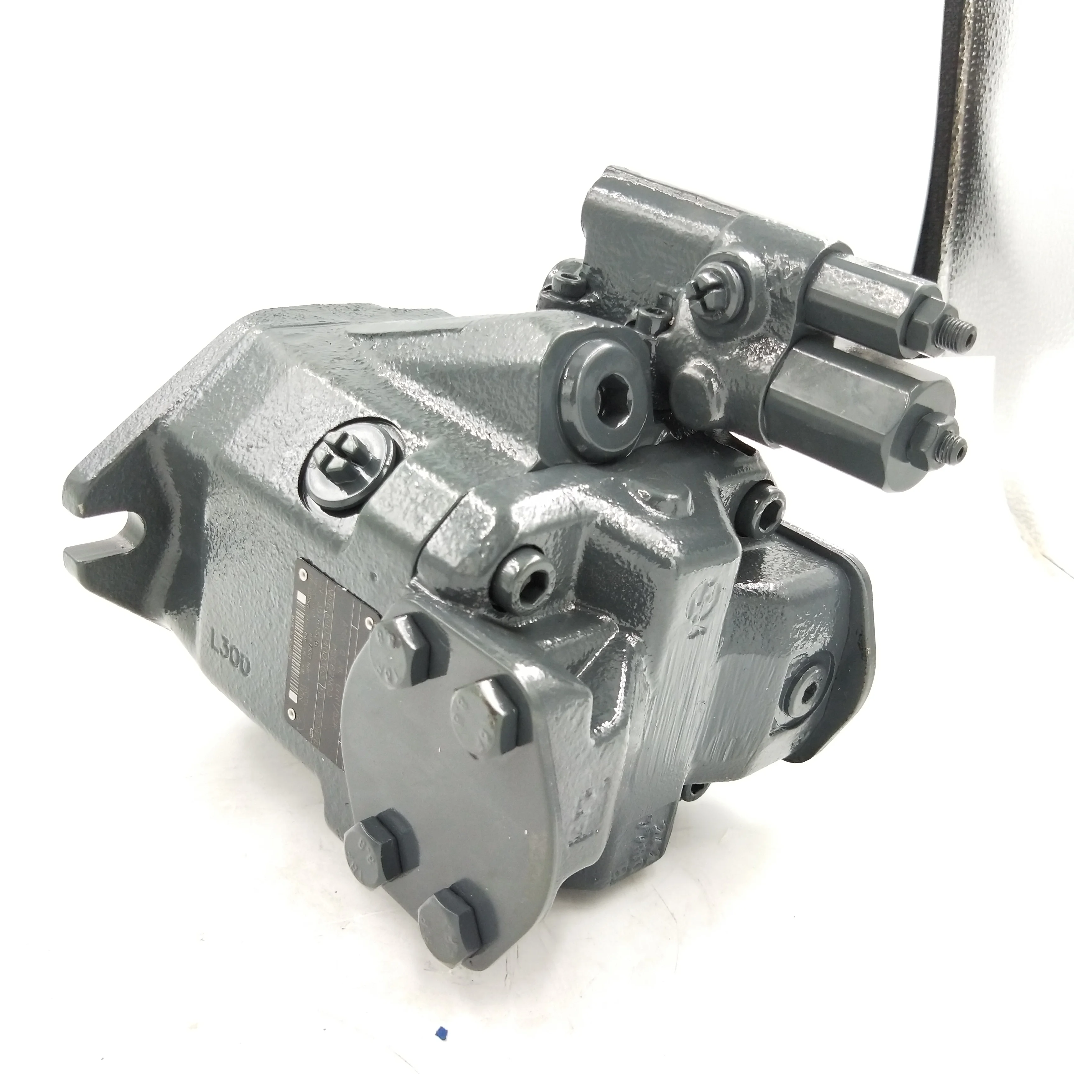
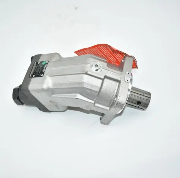
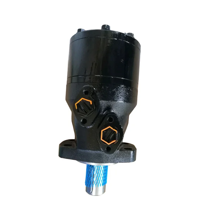
schwing hydraulic pump free sample
The star of Hollywood’s treatment facility is manufactured by Schwing Bioset, Inc. of Somerset, WI. The patented Bioset process produces Class A/EQ biosolids in full compliance with 40 CFR Part 503 Rule.
The wastewater treatment effort in Phoenix has kept pace through a combination of results-driven equipment upgrades — particularly its solids pumping function — and a renewed focus on equipment maintenance. On a daily basis, the 91st Avenue Wastewater Treatment Facility handles better than 150 million gallons of sewage, processes over two million gallons of sludge, and removes 100 dry tons of processed “cake” for sanitary landfill disposal.
Few operations have a need for good, workable, reliable contingency plans as do wastewater treatment plants. Where other industries can deal with issues such as plant disruptions or maintenance downtimes by stopping operation, departments charged with handling and treating our wastewater simply don’t have that luxury. Establishing such an alternative approach became “job one” for the City of London (Ontario) when its incinerator, the primary tool in its disposal effort, reached its end of life. Looking at an extended downtime period and expensive landfill disposal fees city officials searched for an alternative and found it with the addition of a Schwing Bioset wastewater treatment system.
It has been said that the only constant in life is change, and the wastewater treatment plant (WWTP) serving Ypsilanti, Michigan and surrounding areas is certainly doing its part to prove out that adage. Through it all, the focus on quality throughout the plant has never wavered. Nowhere is that more evident than in the facility’s sludge treatment area. A complete solids handling system, including four Schwing Bioset KSP 65 pumps and a series of sliding frame silos, provides primary and backup service, ensuring multi-level redundancy— and peace of mind—to this model of WWTP efficiency.
When the most recent expansion plan is complete, the Kelowna plant will keep their original Schwing Bioset KSP 17V(K) operating as a backup role for a new Schwing Bioset KSP 45V(HD)L and SD 350 screw feeder.
Learn how a pair of Schwing Bioset KSP 110V(HD)L pumps at the Detroit Wastewater Treatment Plant (WWTP):Take high solids-content cake from the dewatering operation to either incineration or a truck loading area
Download the full application report to learn how the pair of pumps have improved the efficiency of incineration and haul-off operations at the plant!
Almost everything about the Stewartstown Borough’s WWTP speaks to its diminutive size. Though it’s located on 20+ acres, the facility itself occupies a footprint of less than an acre. What the plant lacks in size, capacity and cost, however, it more than makes up for in overall performance. In fact, since expanding, the facility has improved the quality of water being discharged into nearby Ebaugh Creek and, with the help of a Schwing Bioset system, creates better than 120 dry-tons per year of Class ‘A’ Biosolids—all of which is used by area farmers.
Download the full application report to learn how a pair of KSP 50 sludge pumps from Schwing Bioset have helped turn land that was once an eyesore into vibrant and pristine land once again.
In this application report, find out how Schwing Bioset"s "muck" pumps helped tunneling crews deliver their thick mixture from a boring machine to waiting trucks on the surface.
Though it is well past its boom times as a supplier of iron ore to the world, the Iron Range area of northeast Minnesota has a continued need for infrastructure support to those who call the area home. The residents reply upon the half million gallon per day (gpd) Colerain Bovey Taconite Wastewater Treatment Plant. The WWTP completed an expansion including a new approach to biosolids disposal, which includes a Bioset reactor from Schwing Bioset to produce Class "A" biosolids.
As a result, many companies are pulling high quality ore from areas once viewed as unreachable. Montana"s Stillwater Mining Company has been successfully employing this approach for more than a decade, and with the help of a KSP 80H(K)R pump from Schwing Bioset to deliver the paste for that process, has literally "gone where no man has gone before."
The Southerly Wastewater Treatment Plant sets the standard with their sludge disposal efforts. Using a quartet of heavy duty pumps and a number of sliding frame components from Schwing Bioset, Inc., cake can either be routed directly for incineration or sent to a pair of storage silos. Once in the silos, the material is readily available for truck-loading and transport.
Water is a critical element in any mining effort. When that water contains solids with trace amounts of gold, there is an effort to focus on material recovery. Such is the case at the Turquoise Ridge gold mine, where a pair of Schwing KSP-50 sludge pumps are being used to get dewatered material to a site where its highly-valued content can be recovered.
While a number of different drying methods exist, the Potash Corporation of Saskatchewan reports that its Allan, SK, plant, by combining higher concentrations of water with the use of fluid bed dryers from Schwing Bioset, has significantly lowered material degradation rates.
Read about the installations and how Schwing Bioset"s push floor bin and biosolids piston pump have risen to the challenge. The pump has its work cut out for it, taking material that is in the 26-28% solids range and sending it more than 65 feet straight up.
It found its answer in a facility redesign centered around use of the Bioset process (Schwing Bioset, Somerset, WI) to create a Class A biosolid. Today Immokalee WWTP has a handle on its disposal, has reduced associated charges by better than two-thirds, and is using that newly-created product for area application.
So when a new plant that Davidson Water, Inc. had recently inaugurated started producing levels of solids almost double what it had anticipated, the company worried that all its advance planning was for naught and the dewatering facet of the process was doomed. However, one of the key components in that effort, a new screw press from Schwing Bioset (Somerset, WI), met the challenge, giving plant operators the results — and the peace of mind — they needed.
On that last point, plant officials opted to replace an outdated and difficult to maintain batch filter press with a different technology altogether — a fully-automated (Schwing Bioset) screw press — to handle its dewatering needs. In doing so, they not only eliminated an ongoing maintenance headache, they also dramatically improved the efficiency of their dewatering operations as well as their overall residuals management operation.
The end result of those efforts is a new Class A Exceptional Quality (EQ) product created through use of the Bioset Process from Schwing Bioset, Inc. (SBI, Somerset, Wisc.) which effectively creates 120,000 pounds of field-ready fertilizer product per day.
Once solely dependent upon liquid applying its Class B byproduct, the District’s Sugar Creek Wastewater Treatment Facility recently upgraded its process to include a pair of fully-automated screw presses and a Class B alkaline stabilization system from Schwing Bioset, Inc. Today, with a viable option to that liquid process in place, the plant is generating more than 17,000 lbs. of Class B cake monthly, and has peace of mind that its biosolids effort is poised for future growth.
When an upgrade to the biosolids dewatering component at the Westbrook/Gorham Regional WWTP was needed, plant personnel looked at several different available technologies. Handling secondary sludge alone is challenging, and after an extensive trial and evaluated bid process, they opted for a screw press from Schwing Bioset Inc.

The 5” SCC touch screen allows operators to safely switch between pumping and driving modes. The system will not allow the transfer case to switch if unsafe conditions are present. The transfer case will not switch; if the drive shaft is turning over 20 RPM, the truck is in drive gear, the parking brake is not set or if the clutch is not depressed. The SCC will display under speed and over speed warnings if the gear ratio is not correct (lower gear than what is required). It will also warn operators if the machine over speeds the hydraulic pumps, in that event, SCC will reduce RPM’s back to idle and flash outrigger lights. Status messages provide the operator valuable feedback if faults occur.
Operators can also raise or lower installed pusher axles, turn on outrigger / beacon lights and manually control the truck throttle in Pumping mode. The SCC maintenance screen displays PTO hours, fuel level and drive shaft speed. System inputs and outputs are displayed on the PLC IO screen, assisting in troubleshooting. The whole system can be bypassed via key switch in the event of system failure.

For decades, stationary concrete pumps from SCHWING has been used for demanding, significant and record-breaking construction projects worldwide. Even under difficult operating conditions, they offer performance, reliability and safety in the high and long-distance pumping of concrete. Nowadays, in addition to cost-effectiveness and productivity, which are achieved by our EcoClean cleaning concept and the optional SmartSwitch technology, state-of-the-art exhaust gas cleaning is also necessary. This can either be achieved by state-of-the-art diesel engines or emission-free electric motors - for example, for smart use in city centres.
As we know, concrete pumps are a maze of hydraulic technology. There are many separate components that all must function properly in order to do the simple task of a piston moving and pushing concrete through a pipe. Hydraulics are actually pretty easy if you take a few minutes to understand what is happening here.
The basic system is comprised of a pump to move the fluid, a motor or cylinder that does the work, a reservoir to store fluid and a power source that drives the pump. The magic is in the control devices that direct the pump, the cylinder, the tank, and the motor to do what is needed at the appropriate time. Lets look at pumps first.
There are several types of hydraulic pump that we may see in our machines. Usually they are either gear type or axial piston pumps, the later being the most common in concrete pumps. A gear pump is exactly what it sounds like, a set of gears that mesh in a housing with passages and ports to direct the fluid under the pressure created by the turning gears that capture and expel the fluid under pressure. These pumps are not usually found in a place where hi-volume is required, as they are better at producing hi-pressure. Gear pumps are also pretty dependable and have a long service life.
Axial piston pumps are more adept at higher volume applications because of the design that has several pistons much like an engine, except these pistons operate in a very different way, with out the use of a crank-shaft. How is this possible? Rotation. A carrier assembly, commonly called the “barrels” rotates under power from an external power source through a shaft. The barrels may have 6 or more holes much like the revolving barrel of a six-shooter handgun. In each hole is a piston, usually made of brass or a similar soft metal. Each piston has a connecting rod that hangs from the back and extends out of the barrel. All of the rods are then positioned against a round plate that has similar dimensions as the barrel. This plate is able to shift position like the butterfly in a carburetor. When it does so, a rod will be drawn out or back in the barrel as the rods on the opposite side are pushed in. these pistons push fluid as they travel back and forth in the barrels. The whole assembly rotates with the plate flopping back and forth pushing and pulling pistons in and out of the barrel as it spins. The entire assembly is called “the rotary group”. 6 pistons the size of a quarter in a barrel rotating at hi-R.P.M. can move a tremendous amount of oil at extremely hi-pressure. The two things that effect the out put of this type pump are plate position and engine R.P.M. these pumps are more likely to be found in today"s concrete pump because of their ability to move large quantities of fluid under pressure. They are not as durable as gear pumps, and can be easily damaged because of the amount of internal contact area requiring constant lubrication. This larger metal to metal contact area is also why we can get more volume out of these pumps. These pumps are precision built and will provide long service life if maintained and not over sped. They, as anything that rotates can and will come apart if run above the recommended R.P.M. for any period of time. The easiest way to destroy one of these is to over-speed the pump. Another way is to cavitate the pump. Cavitation is air being circulated in the hydraulic system and circulated by the pump. Hydraulics work because you cannot compress fluid. Apply pressure to fluid and it will move, every time. Contain it and you have a source of power. Air is different. It will compress. When trapped in a system and circulated into an axial piston pump, it will compress and compress more and more being trapped in the pump body. As air is compressed in this way under the pressures in a pump, it is like steel shot beating hell out of the delicate metals in the pump. Remember these things are made of brass. This is because of the need to expand and contract and still maintain a constant seal. When these air bubbles are bouncing around they will do a lot of damage in seconds. The lack of lubrication for just a second will also do its damage to the mating surfaces. Cavitation is real obvious, when you hear it, its probably too late and the damage has been done, but not always. It sounds like a screech or a scream from the pump. That sound is the pump dying!
Never under any circumstances run a hyd pump low on oil. The hyd oil is the same as the blood in your body and every bit as important. It also must be in good condition, meaning clean and the proper viscosity for the operating climate. In an emergency, whatever you have is better than running on empty or sucking air into the pumps. I have seen guys put water or motor oil in the tank in an emergency after loosing all their hyd oil from a blown line or fitting. This is better than running it dry, but not much. Water will not lubricate the delicate moving parts and will do damage if run for very long. Hyd oil is formulated to work with the metals in the pump. It has acids and other additives for wear resistance and to maintain a stable viscosity. In fact, hyd oil is water-soluble meaning it will mix with water. Ever seen milky hyd oil in a tank? Its water mixed in with the oil. It may never separate on its own like common oil would. That’s why we drain the tank DAILY to remove the water inside that has appeared from condensation from a hot tank that cools off in the evening when parked. The water that appears from condensation will not mix with your oil in the tank unless it is of sufficient quantity to make it through the pumps. Notice that most hyd oil suction lines are installed a little above the bottom of the tank for this very reason. Some systems run suction directly to the pumps, others have filtration between the tank and the pump. If yours is not filtered on suction, it will be on the return side where the oil is cleaned before it returns to the tank.
Filtration is also very important in a hyd system. As the pumps work they wear. The wear is so little so slowly in a well maintained system that it takes years for significant wear to become obvious. Never the less it is happening all the time. Contamination from outside sources is probably the biggest reason to filter constantly. Remember what your machine is doing. Operating a delicate hydraulic system in sand and gravel with dust and water always present. The very things that are fatal to hydraulics! The filters save your pump every time you put it in PTO. Check them according to the manufacturer schedule.
As of late, we are seeing a new generation of axial piston pumps. We have had the “banana” pump for some time; it is a fixed displacement pump, which is what we need for a boom pump having flow at any speed. A main pump, larger, is most likely a ‘variable displacement” pump. This means that it"s out put can be changed by engine RPM or the angle of the swash plate which controls how much travel the pistons have. These will generally be at or near a neutral position at idle and will produce flow at any increase in speed. Here is where we will see a few different styles of main pump. The standard single phase or single discharge port has been around forever simply providing flow to a control block that then directs the oil to the correct servo. Now we have multi port pumps which actually oscillate between different ports sending oil in one direction then another without the aid of a control block assembly. It is almost the same thing except the multi port pump does all the work and there is less change over time in the pump cycle. The control block is eliminated and the only other thing required is a small control valve that helps signal the pump to pressure either “a” port or “b” port. This smaller valve is much faster and easier to move than the 2lb spool required on the single port pump. Both have some advantages and disadvantages, rendering the difference purely a matter of personal preference.
The pump is turning, pushing oil somewhere. How does it know to push oil? This is the job of a relief valve and/or solenoid, or off/on valve. This devise, usually electrically activated opens or closes allowing oil to flow under pressure to the servo, motor or cylinder or, simply flow in a circle back to tank where it will make a continuous loop until a different signal is received. This is what happens when your concrete pump is in neutral, the pump is still turning and working, just not sending oil to anything except the tank. When you put the pump in forward you are blocking the easy passage to tank and sending the oil to the cylinder, which will now move. The basic idea is that liquid cannot be compressed, so when it is contained and has sufficient force or pressure, it can and will move whatever it is directed at. When contained and under pressure, fluid acts as a solid transmitting the energy of pressure to a working part. Now, what keeps the pump from blowing up if it cannot move whatever it was sent to do? A relief valve does this. It is a spring-loaded valve like a regulator that will block a passage to tank until a set pressure is reached. At this point it will open and allow the oil to go to tank instead of self-destructing. Ever had a plug in a concrete pump and heard that screaming? That’s the relief valve opening under hi-pressure. Sometimes called a safety valve, it has a hard life handling a hi-volume of oil at an extremely hi-pressure. Avoid working this part too much. If it fails to operate, life can get tough in between heartbeats while your main pumps explode. While there are many different system designs from different manufacturers, the basic hyd system is the same, a pump, working parts and it’s control systems. Knowing how it works will help you in your daily activities knowing that when your concrete pump fails to do anything when you switch to forward pump, you now know what must happen for it to work, therefore you have the ability to find what is not right, possibly the off/on solenoid or fuse, or a stuck valve. You know where to look.
Now that we can turn it on and off, we can now see how to direct the oil to all the working parts, cylinders, agitator motors, concrete valve etc. there are going to be several hyd pumps in a concrete boom pump. Each has a task and will operate independently of the others. Some all feed from a common tank, some have two tanks and separate systems for the boom and the concrete pump. Learn the machine that you are running and discover what kind of system that you have. As the pumps are pushing oil to the drive cylinder, you know what will happen next, it will cycle, change direction as the concrete valve shifts and the drive cylinders change direction. Signal ports at various places in the working cylinder accomplish this. As the piston in the hyd cylinder reaches the end of its stroke, it passes a port allowing oil to flow to the control block or valve and “signal” the control to move a valve or spool which then directs oil in the opposite direction. As the second stroke or cycle completes, the same thing happens again, thus you have automatic cycling. Pretty simple so far! This is how the concrete valve knows when to move and when the drive cylinders know to change direction. Putting your concrete pump in reverse is simply moving a spool or control valve to an out of phase position. This will throw the cycle 180 degrees out, and everything will continue as normal until the reverse switch is released and normal cycling phase is re-established.
Some manufacturers are now using electrical sensors to send the signal to a solenoid that will send a spool over thus changing the cycle. This system is a bit quicker than a basic hyd control, but it has more parts and is more complex. You should be familiar with the type of system on your particular pump and know where the sensors are and where the solenoids are which always have some kind of manual control in case of electrical failure. Even if you loose all electrical in the pump with no hope of restoring power as described in the previous article on electrical problems, you can still cycle the pump to finish the pour at least until help arrives. You can fold the boom or even pour walls depending on how well you can handle the manual controls. I would suggest everyone practice this emergency procedure so that you can be prepared if/when it happens.
Having so many different designs in so many different manufactures, it is hard to describe the hyd system of them all with out looking at each make and model. So, we will keep this as generic as possible. Now that we understand how the pump cycles and how we get reverse pump, lets look at the accessories and their drives. Besides the mains, which power the concrete pump, there will be a boom pump, maybe an accumulator pump, and perhaps an accessory pump. The banana shape can usually identify the boom pump. It will have a slight bend in the body. This is to keep the rotary group at some flow all the time. This allows you to have flow at idle and up allowing the boom to move at any speed. The boom circuit works in a similar way as the pump circuit except that its many cylinders are all different in what they require and how much. The swing for example will most likely be independent of the rest of the boom circuit because it is more closely regulated and also may have to operate a brake. The swing will have its own pressure relief and a safety setting. This limits the load that the swing motor or cylinders will handle. If your pump is too far out of level and will not swing up hill, it is designed that way so the turret gear and swing assembly will not be damaged by excessive torque. Too much power to the swing and it would twist it self-apart. It does run off the same pump and same general circuit, but it is separate in the pressure and relief system. The other boom cylinders are all metered too. Each will have holding valves with safety settings so that the boom will lift only so much weight. These are not cranes; we do not lift 50’ trimmie pipes because they were not designed to do this. They are designed to lift their own weight and THAT IS ALL! The holding/safety valves limit what we can do for our own good. There may be orifices in the line somewhere to limit the speed of the boom cylinder. Some of these are adjustable and should be set according to factory specs. Even with the proportional booms we have now, they have built in safety limits. They are designed to be gentle and graceful not flyswatters. In any boom hyd system you will find a main relief that will limit pressure to the entire system. Know where this is. On occasion these may fail or stick not giving you any pressure to move your boom with. If this ever happens, sometimes a simple tap on the relief will free it. Don’t beat on it, tap it. Some reliefs have an adjustment screw in them. These must only be adjusted when a gauge is present or you can over pressurize the system and start blowing hoses apart one after another. The boom pump as small as it is, will supply enough pressure to blow apart almost anything. These pumps are not designed to move massive amounts of oil as the mains are, they are designed to move sufficient oil under high pressure to operate the heavy load of a boom cylinder. Always check the hoses on the boom circuit, as they tend to jump around more due to the off/on nature of the boom system. Look for rubbed spots in the rubber liner on these and all hydraulic hoses. Wrap them in a piece of heavy-duty water hose and tie-strap the water hose in the area where it will protect the hyd hose. Always check the hoses in the turret of the boom. There are lots of places where a hose can rub through or hang in there, and ALWAYS know which way the boom was folded. There are few things worse than opening the boom the wrong way and twisting off a couple hoses inside. The boom circuit will also have the manual controls necessary in case of a power failure. Learn these controls. When you have several loads sitting there and must continue pumping, that is not the time to be learning. You should be able to feel the levers without looking too often and drive the boom fairly well. The lay out is different on every model, so learn yours. The pump parked next to yours too. You never know. Some models have a completely separate hyd tank and filtration system for the boom. Some operate everything from one tank. All will have different filters for the boom and the other systems. Check these according to the factory timetable for the number of hours of operation. Many filtration systems have a by-pass so that if the filter is clogged, oil will continue to circulate. You may never know that you are running unfiltered oil until a hyd pump fails from contamination or relief valves start sticking from the tiniest bit of debris. Filters are cheap compared to buying new pumps!
Charge pumps. These little pumps are found on some models to provide “charge oil” to the control circuit of the concrete pump. The mains are controlled by a lower pressure control system for the control valves that direct the mains. The little charge pumps supply this low pressure for control purposes, but are as important as any on the machine. With out the charge pump, you would not be able to turn the concrete pump on because they are “in” charge of the main pump control system. You send the charge pump a signal; it sends the main pump a signal. A very important link in the chain.
Accessory pumps do exactly what they sound like. They are low volume pumps that simply supply oil pressure to turn the agitator and water pump. Some are used in conjunction with the concrete pump circuit to supply low pressure from return to operate control valves. Some are the source of cooling as they circulate oil at a lower pressure and do so constantly while turning some agitators. Again, every system is different so know yours. A few things that all systems have in common are control valves, relief valves, suction and pressure lines, and filtration. Take the time to visually inspect and follow the lines from the pump to the control to the actual working part. This will help you is case anything ever fails because you will know where all the components are. The systems that are in production today are extremely complicated and no body expects you to know everything about them, but you are expected to know where the basic components are and what they do so that when something does go wrong, you can communicate with a mechanic and get the problem resolved. When there is mud on the job and you are down, that is not the time for searching for a part. Know where it is and what it does.
Accumulator pumps: these are pumps that simply charge an accumulator that is used for dampening or for pre-tension on a system, usually the concrete valve. Because the concrete valve requires hi pressure to move and is under a heavy load and must do it with out hesitation, the hyd pumps will take too long to supply enough pressure to do this, making the valve slow and late in shifting. The accumulator is a nitrogen filled balloon that always has the required pressure available when the signal to shift is sent. It gives the hyd system a boost to make the valve move now, not in a second or two. The accumulator pump re-charges the balloon in the time it takes the drive cylinder to complete another stroke being ready again to shift the valve when the signal arrives. The accumulator maintains pressure on the system for instant movement. Some are used as shock absorbers to take the spike out of a system when a spool moves sending oil in a different direction keeping a move consistent level of pressure instead of high"s and lows in the system while the main hyd pumps “catch up” to the demand.
Boom safety valve with lever (Schwing) some models are so equipped with this to operate the boom in case of electrical failure. These models are normally running zero pressure until a command or signal is sent to a function. Turning the safety valve builds pressure thus permitting boom operation.
With ever increasing complexity in the newer hyd systems that we are seeing today, a good basic understanding of how a particular system works is required in order to trouble shoot a downed concrete pump on the job. It may be difficult to tell whether the problem is electric or hydraulic when something fails to function. Having this understanding will help you in making that determination and help with the diagnosis and repair while on site. Almost any system failure can be dealt with if you know where to look and what to look for. You agitator does not come on. Is it getting pressure or is it not receiving the electrical signal to activate the solenoid that permits the flow of oil? The pump will not reverse. Is the spool stuck or the relief stuck or is the wire to the solenoid broken? A boom function will not work. Is it getting the signal from the remote to the stack valves or is there a problem in the boom relief valve? These are the types of questions that you should be able to answer should any of these and countless other potential problems arise during a pour. They rarely appear in the yard where tools and mechanics are available. If you are uncertain as to the function of any of the components or location of any of these parts, get with a mechanic or manager and have them point them out to you. Get someone that is knowledgeable about your machine and learn how to do everything manually and where to look for the things mentioned above. It is for your own benefit and the benefit of the company that you work for and the contractor that has trusted in your ability to pump his concrete. Know what you are doing, and be a pro.

Avoid any downtime at your construction site with the range of schwing hydraulic pump from Alibaba.com. You can check out the fully-stocked parts at Alibaba by manufacturer and model and affordable wholesale prices. The wholesale schwing hydraulic pump collection of spare parts from China’s wholesaler, Alibaba, fits well with a wide range of heavy-duty equipment, from bulldozers, excavators, and hammers, among others. Plus, you can find parts for your tractors, skid steer loaders, wheel loaders, backhoe loaders, and crawler dozers.
If you have a limited cash allocation, the used or remodeled parts will go a long way in accommodating your budget. Alibaba’s schwing hydraulic pump and tools make it easy to replace, modify and enhance your equipment for their optimal performance. For electrical and mechanical applications, you can find your match at Alibaba.com for everything you need to make your vehicle perform better. Get engine oils, batteries, hydraulic parts, transmissions, injectors, hoses, and starters from the schwing hydraulic pump at Alibaba.com.
The new parts from manufacturers have warranties, and you can buy them by matching the part numbers. Such parts, including hoses, plugs, or filters, will help you quickly deal with downtime on site. The used parts, on the other hand, sell for a lower price. Remember, Alibaba partners with sellers who have certificates of operation. So, you can use these second-hand schwing hydraulic pump to get your heavy machine running. You can also get rebuild models from the collection at Alibaba.com. These are sustainable choices that use recycled materials and perform as well as the new parts. And depending on your seller of choice, you might get a warranty to accompany them.

Ball valve sequencing of the hopper and twin cylinders is the simple, easy to maintain method that appeals to most grout pumpers. The outlet manifold is fitted with a spring-type surge chamber for safety and smooth concrete flow.
*Pumping distances shown are to be used as a guide only since they have been considerably exceeded on specific projects. Maximum attainable distances depend upon concrete mix design and pipeline diameter. Maximum output and distance cannot be achieved simultaneously.
Slick Willie 2 concrete pump primer is a product designed to avoid concrete hoses to plug during the first strokes pump job. This non-Alkaline product is applied into your pumping system before every job, lubricating the walls of your hoses or pipes, which allows the concrete to flow smoothly.
Concrete pump primer is one of the cheapest insurances and this is why. When concrete is first pumped into the hoses, it will loose water in the process. This water would be absorbed by the dried hoses, causing concrete to loose its pump ability, so YES, you DO need to prime your system.
Say you start pumping 200 feet with a 6″ slump, at the end of 200 feet, you might end up with a 4″ to 3″ slump depending on the heat and conditions of the concrete, giving you as a result a higher chance of plugging your lines up. So It’s important to lubricate the walls of your system, you can do this with a concrete pump primer, Portland cement or just water.
Concrete pump primer: this product is designed to solve the problems above. First is environmentally friendly, biodegradable, easy to use in small convenient 4 oz. bags, it becomes like a jelly that coats completely the walls of your hoses or pipes.
Slick willie 2 is Americas favorite concrete pump primer, this industry leader combines speed and performance like no other primer before, the primer formula is packaged in compact 4oz. bags, making storage and transportation simple. Slick Willie 2 is safe for the environment and great for your pump and hoses.
Concrete pump primers are extremely important for your concrete pump. It ensures that the concrete being pumped, can make it easily through the hoses when you first start pumping. This biodegradable material will ensure the longevity of your hoses and the ease of use on your concrete pump. What happens is once you start pumping, your hoses will start taking water away from the mix reducing the pump ability of the material therefore causing you to plug and delay your job.
Concrete pump primer basically creates a gellous material that will coat the walls of the hoses as concrete travels through it. Basically, you apply the concrete pump primer first and you start pumping it into your hoses, and then you pour the concrete into the hopper and pump it down, having the concrete pump primer in front of the concrete material. And since it is biodegradable, you can pretty much allow it to be disposed of anywhere in the job site.

The present invention relates to systems for transporting high solids materials such as concrete. In particular, the present invention relates to a concrete pump monitoring system which monitors the operation of a concrete pump and provides its owners and operators with information relating to the operational performance of the pump and generates maintenance and warranty information based upon the operational performance.
Positive displacement pumps are frequently used for conveying concrete and other materials through pipelines in construction applications. An example of a positive displacement pump of this type is shown in Oakley et al., U.S. Pat. No. 5,106,272 entitled SLUDGE FLOW MEASURING SYSTEM. Positive displacement pumps offer a number of significant advantages over screw or belt conveyors in the pumping of materials such as concrete. For example, positive displacement pumps are capable of pumping thick, heavy materials which may not be practical for screw conveyors. Pump and pipeline systems also take up less space than screw or belt conveyors and, with the use of simple elbow pipes, are capable of transporting concrete around corners. Additionally, positive displacement pumps offer a reduction in noise over mechanical conveyors, as well as greater cleanliness and reduced spillage.
In concrete pumping applications, it is becoming increasingly necessary to accurately measure the quantity of concrete pumped. Even more importantly, owners must schedule the proper maintenance and replacement of pump and pipeline components prior to a component failure during use. This prevents unnecessary and costly loss of time due to system failures, as well as the inefficient waste of concrete which may become unusable as a result of the delays associated with the failure of a pump or pipeline component. At the same time, for economic reasons, it is desirable to schedule the maintenance and replacement of pump and pipeline components only when necessary.
In the concrete pumping business, pump maintenance is typically scheduled based upon the number of cubic yards of concrete that have been pumped. The pump owner frequently estimates the cubic yardage of concrete pumped by referring to the concrete supplier delivery tickets. Additionally, current methods of scheduling maintenance do not take into account factors such as the type of concrete which has been pumped or the rate at which it was pumped. Different types of concrete have different abrasion characteristics and, when pumped at any given velocity, will cause different amounts of wear, and require different pumping pressures. All of these factors lead to uncertainty as to when maintenance needs to be scheduled. Additionally, these factors make it difficult for pump and pipeline manufacturers to verify warranty related information.
The present invention is based upon the recognition that a positive displacement pump, together with a system which monitors the operational parameters of the pump and which is capable of calculating theoretical and actual volumes of concrete pumped, instantaneous pumping rates, and the pumping pressure during each pumping stroke, offers the combined capability of accurate volume and flow rate measurement as well as the capability to predict pump and pipeline component wear and to generate maintenance and warranty information.
It is not normally possible to fill the cylinders of a positive displacement pump to 100 percent of the known capacity. Therefore, a portion of each pumping stroke of the positive displacement pump involves traveling through voids to pressurize the concrete. While traveling through voids in the cylinder, little force is required to move the piston. In the present invention, at least one parameter related to the operation of the positive displacement pump is sensed in order to identify the point during the pumping stroke when the hydraulic pressure applied to the piston is sufficient to exceed a predetermined value. From that information, the actual volume of material being pumped during that pumping stroke is determined. By accumulating the actual volume pumped during each stroke, an accumulated actual volume is determined. By dividing the actual volume pumped during one or more pumping cycles by the time that elapses during the pumping cycles, an instantaneous pumping rate can be determined.
In one preferred embodiment, the monitoring system of the present invention senses a parameter related to the operation of the pump which bears a known relationship to an actual volume of concrete delivered during a pumping cycle. From the sensed parameter, an output value is determined which represents an actual volume of concrete delivered by the pump during a pumping cycle. The actual volume of concrete delivered is stored in the memory of the monitoring system of the present invention. The monitoring system of the present invention then provides the stored information on actual volume pumped to pump users.
In another embodiment, the monitor system of the present invention calculates an actual volume pumped and an instantaneous pumping rate for each pump stroke and over a plurality of pumping strokes. The monitoring system also senses the pumping pressure during each of the pump strokes. Next, the velocity of the concrete pumped is calculated. Finally, the monitoring system predicts pump and pipeline component wear based upon the velocity of the concrete pumped and the pumping pressure during each pumping stroke. The predicted wear information is stored and provided to owners of the pump upon request for maintenance scheduling and warranty verification.
FIG. 1 shows two-cylinder, hydraulically-driven, positive displacement material pump 10 and pipeline 11 which is connectable to pump 10. Pump 10 includes material cylinders 12 and 14, material pistons 16 and 18, hydraulic drive cylinders 20 and 22, drive pistons 24 and 26, valve assembly 28, hopper 30, pivoting transfer tube 32, outlet 34, hydraulic actuators 36, pivot arm 38, hydraulic pump 40, input shaft 41, high pressure lines 42, hydraulic reservoir 44, filter 45, low pressure lines 46, and forward and rear switching valves 48 and 50.
Material pistons 16 and 18 reciprocate in material cylinders 12 and 14 respectively. Hydraulic drive cylinders 20 and 22 have drive pistons 24 and 26, respectively, which are connected to material pistons 16 and 18, respectively. Valve assembly 28 controls the sequencing of movement of pistons 24 and 26, and thus the movement of pistons 16 and 18 in material cylinders 12 and 14.
Concrete or other material is supplied to hopper 30, in which a pivoting transfer tube 32 is positioned. It should be noted that pivoting transfer tube 32 represents only one type of material valve, and that other types can be used as well. Transfer tube 32 connects outlet 34 with one of the two material cylinders (in FIG. 1, outlet 34 is connected to cylinder 12), while the inlet to the other material cylinder (in this case, cylinder 14) is opened to the interior of hopper 30. In FIG. 1, piston 16 is moving forward in a discharge stroke to pump material out of cylinder 12 to outlet 34, while piston 18 is moving rearward to draw material into cylinder 14. Outlet 34 may be connected to pipeline 11 so that concrete is pumped through outlet 34 into pipeline 11.
At the end of the stroke, hydraulic actuator 36 which is connected to pivot arm 38 causes transfer tube 32 to swing so that outlet 34 is now connected to cylinder 14. Then, the direction of movement of pistons 16 and 18 reverses, with piston 18 now moving forward in a discharge stroke while piston 16 now moves backward in a filling or loading stroke.
Valve assembly 28 is coupled to hydraulic pump 40 and hydraulic reservoir 44 through high and low pressure lines 42 and 46 respectively. Oil or any other type of hydraulic fluid is pumped from hydraulic pump 40 through high pressure lines 42 to control valve assembly 28. Valve assembly 28 includes check valves which control the sequencing of high and low pressure hydraulic fluid to hydraulic cylinders 20 and 22 and to hydraulic actuator 36 in a known manner. Low pressure hydraulic fluid returns to hydraulic reservoir 44 through filter 45 from valve assembly 28 via low pressure line 46.
The sequence of operations of pump 10 is generally as follows. As the drive pistons 24 and 26 come to the end of their stroke, one of the material cylinders (in FIG. 1, cylinder 12) is discharging material to outlet 34, while the other cylinder 14 is loading material through its inlet from hopper 30. At the end of the pumping stroke, material piston 16 is at its closest point to outlet 34, while piston 18 is at a position furthest from outlet 34. At this point, switching valve 50 senses that hydraulic drive piston 26 has reached the rearward end of its stroke. Valve assembly 28 and hydraulic actuator 36 are activated which causes transfer tube 32 to swing so that outlet 34 is now connected to cylinder 14 instead of cylinder 16. The operation continues with one material piston 14 or 16 operating in a filling stroke, while the other is operating in a pumping or discharge stroke.
FIG. 2 shows a preferred embodiment of the present invention in which operation of concrete pump 10 is monitored by system 100 to provide the owners and operators of concrete pump 10 with accurate operational, diagnostic and maintenance information. Monitor system 100 includes computer 102, which in a preferred embodiment is a microprocessor-based computer including associated memory and associated input/output circuitry. Monitor system 100 also includes clock 104, output device 106, input device 107, and pump sensors 108-122 which will be described later in greater detail.
Output device 106 is preferably any of a number of devices. For example, output device 106 can include a display output such as a cathode ray tube or liquid crystal display. Output device 106 can also be a printer, or a communication device such as a cellular phone which transmits the output of computer 102 to another computer-based system (which may monitor the overall operation in which pump 10 is being used). Input device 107 can also take a variety of forms. In one preferred embodiment, input device 107 is a keypad entry device. Input device 107 can also be a keyboard, a remote program device or any other suitable mechanism for providing information to computer 102.
Pump sensors 108-122 monitor the operation of pump 10 and provide signals, representative of pump operation, to computer 102. The parameters sensed by pump sensors 108-122 provide various indications of pump operation and performance and provide computer 102 with information needed to generate performance and diagnostic information for the pump"s owner and operator. In preferred embodiments of the present invention, computer 102 is also programmed to control certain operational aspects of pump 10 in response to the signals received by sensors 108-122.
It should be understood that monitoring system 100 may include some or all of sensors 108-122. Some of sensors 108-122 provide computer 102 with duplicative information and could therefore, in other embodiments, be omitted from monitoring system 100. Hydraulic system sensors 108 provide an indication to computer 102 of the start of each pumping stroke in pump 10. Sensors 108 also provide an indication of the time at which each pumping stroke ends. Additionally, hydraulic system sensors 108 provide information to computer 102 on other hydraulically controlled functions of pump 10 such as the position and operation of transfer tube 32 which swings to connect a different material cylinder 12 or 14 to outlet 34 at the completion of each pumping stroke.
Hydraulic pump pressure sensor 110 senses the pressure of the hydraulic fluid on the high pressure side of pump 10. In addition to supplying computer 102 with hydraulic pressure information, hydraulic pressure signals from sensor 110 are preferably monitored to obtain other information such as the start and stop times of each pumping stroke.
Piston position sensors 112 sense the position of each of the pistons of pump 10 during pumping strokes. From the signals supplied by piston position sensors 112, the starting and stopping points of each pumping stroke are also known. The signals from piston position sensors 112 are, in a preferred embodiment, a digital value. For example, piston position sensors 112 are preferably linear displacement sensors (which may be analog sensors), coupled to an analog-to-digital converter so that the data supplied to computer 102 is in a digital form.
Outlet pressure sensor 114 is preferably an analog pressure sensor or a digital pressure sensor. Outlet pressure sensor 114, as will be discussed later in greater detail, provides computer 102 with signals which, in conjunction with signals from hydraulic pump pressure sensor 110, are indicative of a pump efficiency or fill percentage.
Hyrdraulic flow rate sensor 116 are preferably located near hydraulic pump 40 and sense the flow rate of hydraulic fluid from pump 40. Sensors 116 are also preferably used to provide an indication to computer 102 that the velocity of pistons 24 and 26 have remained essentially constant during the pumping cycle. Hydraulic flow rate sensor 116 is preferably in the form of a digitally converted analog signal to computer 102. In other preferred embodiments, piston velocity is not intended to remain constant, and therefore, sensor 116 is used to adjust the calculated actual concrete volume.
Oil filter sensor 118 senses a change in pressure across oil filter 45 in hydraulic reservoir 44. This information is used to determine whether the oil filter is dirty and needs to be replaced.
Oil temperature sensor 120 senses the temperature of the hydraulic fluid in hydraulic reservoir 44. This information is used to monitor pump 10 for excessive temperature conditions. In preferred embodiments, computer 102 ignores information from sensor 118 until sensor 120 indicates that hydraulic fluid is at normal operating temperatures.
RPM sensor 122 is a proximity switch located on the input shaft 41 to hydraulic pump 40. Signals from RPM sensor 122 provide computer 102 with information relating to the current speed at which hydraulic pump 40 is being driven.
In one preferred embodiment of the present invention, computer 102 monitors the number of pumping strokes by pump 10 and calculates a theoretical volume of concrete pumped. Hydraulic system sensors 108 provide signals to computer 102 which indicate the start and stop of each pumping stroke. Computer 102 uses these signals to count the number of pumping strokes and stores this data in its associated memory. Computer 102 than calculates, based upon the counted number of strokes and upon the known volume of material cylinders 12 and 14, a theoretical volume of concrete pumped. Information relating to the number of pump strokes and the theoretical volume of concrete pumped is stored in the memory of computer 102 for use in predicting wear of pump and pipeline components and for scheduling maintenance. Information on the number of pump strokes and theoretical volume pumped, as well as the generated maintenance information, may be accessed by the user of monitoring system 100 through output device 106.
In alternative embodiments, computer 102 receives information relating to the number of pumping strokes performed by pump 10 from signals provided by hydraulic pump pressure sensor 110 or piston position sensors 112 instead of hydraulic system sensors 108. Using the signals received by one or more of sensors 108, 110, and 112, computer 102 generates and stores data which indicates the total number of strokes and the total theoretical volume pumped by pump 10 over a predetermined period of time, during the current pumping application, since the last maintenance of the pump, and since pump 10 was new.
In another embodiment, hydraulic pump pressure sensor 110 monitors the hydraulic pump pressure during each pumping cycle and provides this information to computer 102. Computer 102 stores this information and provides the user with information indicating the current pumping pressure, the average pumping pressure over a period of time or over a number of strokes, the highest pumping pressure since the last pump maintenance, and the highest pumping pressure ever experienced by pump 10.
In another preferred embodiment of the present invention, computer 102 calculates, for each pumping stroke, a pump efficiency rating or fill percentage. Depending upon the pumpability of the concrete being used, material cylinders 12 and 14 will not likely be totally filled with concrete during a loading stroke. Knowing the total displacement volume of material cylinders 12 and 14, and knowing the fill percentage of the material cylinders during each stroke, computer 102 can calculate an actual volume pumped during any given stroke.
The percentage fill can be determined as follows. As discussed previously, computer 102 receives signals from hydraulic system sensors 108, hydraulic pump pressure sensor 110, or piston positions sensors 112 which are indicative of the beginning of each pumping stroke. As material pistons 16 and 18 travel through material cylinders 12 and 14 during their respective pumping strokes, concrete in the material cylinder is compacted. When the concrete is near fully compacted, the pressure in material cylinders 12 and 14 respectively, and thus the hydraulic pressure in hydraulic drive cylinders 20 and 22 respectively, increases. Computer 102 monitors the signal from hydraulic pump pressure sensor 110. When the signal from sensor 110 indicates to computer 102 that the hydraulic pressure in pump 10 has exceeded a predetermined value, computer 102 records that time (or, in the alternative, the piston position) during the pumping stroke. In alternative embodiments, computer 102 does not compare the hydraulic pump pressure to a predetermined value, but rather to the pressure of the concrete at the outlet of pump 10 or in pipeline 11 which is provided to computer 102 by outlet pressure sensor 114.
Computer 102 next receives a signal from sensors 108, sensor 110, or sensors 112 which indicates that the pumping stroke is completed. Because it is known that concrete can be pushed from material cylinders 12 and 14 only when the hydraulic pressure obtains some known relationship to the predetermined value, computer 102 can determine an efficiency rating or fill percentage by dividing the pumping stroke time (or distance traveled) after the predetermined hydraulic pressure was exceeded by the total pumping stroke time (or distance traveled). Based upon signals from hydraulic flow rate sensor 116, computer 102 determines whether the velocity of pistons 16 and 18 remained essentially constant through the pumping stroke. If computer 102 determines that the velocity did not remain essentially constant, adjustments must be made because this method of calculating fill percentage is actually based upon the ratio of the length of the stroke after the predetermined value has been exceeded to the total stroke length.
The fill percentage for each stroke is stored in a register within the memory of computer 102. Since the total displacement volume of material cylinders 12 and 14 is known, computer 102 can, using the calculated fill percentage, determine an actual volume pumped during each stroke. In addition, computer 102 updates a register which keeps an accumulated total of actual volume pumped.
Using clock input signals from clock 104, computer 102 can determine the length of time of each pumping stroke and an accumulated length of time during which the accumulated total of actual volume was pumped. With this information, computer 102 calculates an instantaneous pumping rate for each cycle, as well as an average pumping rate over the accumulated time. All four values (actual volume pumped in a particular cycle, actual total accumulated volume, instantaneous pumping rate, and average pumping rate) are stored in the memory of computer 102 and can be displayed by output device 106. Typically, the operator will select the particular information to be displayed by providing a command through input device 108 to computer 102. Computer 102 also generates a fill efficiency for the last pump stroke, as well as average fill efficiencies over predetermined numbers of strokes or periods of time.
The actual volume of concrete pumped by pump 10 is a more reliable indicator of component wear on some components of pump 10 and pipeline 11 than is the theoretical volume of concrete pumped. Therefore, this information is useful in scheduling the maintenance and replacement of parts for pump 10 and pipeline 11. In a preferred embodiment of the present invention, computer 102 stores information relating to the actual volume of concrete pumped by pump 10 over several different time periods. These actual volumes and time periods include the actual volume pumped per stroke, that actual volume pumped over some predetermined number of strokes or period of time, the actual volume pumped during a particular job or pumping application, and the actual volume pumped over the life of pump 10 since it was new and since its last scheduled maintenance. Computer 102 then uses this stored information to generate maintenance schedules or adjust existing maintenance schedules.
In other preferred embodiments of the present invention, information relating to the actual volumes of concrete pumped, as well as other information such as pumping pressures or the total number of pumping strokes is resettable only by those who posess a pre-programmed access code. This permits the pumps owners or manufacturers to verify information relating to alleged uses of pump 10, and is a useful tool for providing accurate warranty information.
Three major factors affect the rate that concrete pump and pipeline components experience wear. The type of concrete being pumped, the velocity at which the concrete is pumped, and the pumping pressure all greatly affect component wear. These three factors are each dependent on one another as well. Although it is possible to predict the amount of component wear based, at least in part, upon the type of concrete being pumped, an easier and more reliable method of predicting concrete wear is to base the predictions on the velocity and pressure at which the concrete is pumped.
Using the methods described above to determine the actual volume of concrete pumped per stroke and the instantaneous pumping rate, the velocity of the concrete pumped may be determined. Since the methods described above may be used to determine the instantaneous volumetric flow rate of concrete pumped by pump 10, and since the cross-sectional areas of pump outlet 34 and pipeline 11 are known, the velocity of pumped concrete may be calculated by computer 102 for each pumping stroke. Also as described previously, by monitoring the signal from hydraulic pump pressure sensor 104, computer 102 can determine the pump pushing pressure during the portion of each pumping stroke in which concrete is actually pushed from material cylinders 12 and 14. Computer 102 then uses the velocity and pressure information from each pumping stroke to calculate or update maintenance information for the components of concrete pump 10 and pipeline 11.
In one preferred embodiment, a method of predicting the rate at which pump 10 and pipeline 11 will experience wear is to monitor the operation of pump 10 as it pumps concrete at an average velocity and under an average pumping pressure to determine, on average, how many cubic yards can be pumped before pump 10 and pipeline 11 components need replacement. Using this method, the average velocity and the average pumping pressure are multiplied together to obtain a wear reference value WR. Then, during normal pumping operations, computer 102 monitors the actual pumping pressure and calculates the actual concrete pumping velocity using the methods previously described. Computer 102 multiplies the actual pumping pressure by the actual pumping velocity to obtain an actual wear index WA. Computer 102 next compares wear reference value WR to actual wear index WA. If actual wear index WA is less than wear reference value WR, pump 10 and pipeline 11 components can be expected to pump a higher than average volume before needing to be replaced. However, if WA is determined to be greater than WR, pump 10 and pipeline 11 components can be expected to require replacement before the average volume of concrete has been pumped. In either case, computer 102 adjusts the maintenance and warranty schedules appropriately.
For example, assume that an average pumping pressure is 2,000 p.s.i. and that an average velocity is 2 yards per minute. Also assume that under these conditions, on average, a particular section of pipeline 11 requires replacement after 15,000 cubic yards of concrete have been pumped. In this case, a wear reference value WR of 4,000 would be input into computer 102. Next, assume that over a period of time, an average actual pumping pressure of 2,500 p.s.i. and an average actual pumping velocity of


 8613371530291