
skid steer hydraulic pump problems free sample

Things like restrictions and blockages can impede the flow of fluid to your pump. which could contribute to poor fluid flow. Air leak in suction line. Air present in the pump at startup. Insufficient supply of oil in pump. Clogged or dirty fluid filters. Clogged inlet lines or hoses. Blocked reservoir breather vent. Low oil in the reservoir
Now that we’ve ensured that the directional control is not reversed, it’s time to check that the drive motor itself is turning in the right direction. Sometimes incorrect installation leads to mismatched pipe routings between control valves and motors, which can reverse the direction of flow. Check to see that the motor is turning the pump in the right direction and if not - look at your piping.
Check to ensure that your pump drive motor is turning over and is developing the required speed and torque. In some cases, misalignment can cause binding of the drive shaft, which can prevent the motor from turning. If this is the case, correct the misalignment and inspect the motor for damage. If required, overhaul or replace motor.
Check to ensure the pump to motor coupling is undamaged. A sheared pump coupling is an obvious cause of failure, however the location of some pumps within hydraulic systems makes this difficult to check so it may go overlooked
It is possible that the entire flow could be passing over the relief valve, preventing the pressure from developing. Check that the relief valve is adjusted properly for the pump specifications and the application.
Seized bearings, or pump shafts and other internal damage may prevent the pump from operating all together. If everything else checks out, uncouple the pump and motor and check to see that the pump shaft is able to turn. If not, overhaul or replace the pump.
If your pump is having problems developing sufficient power, following this checklist will help you to pinpoint the problem. In some cases you may find a simple solution is the answer. If your pump is exhibiting any other issues such as noise problems, heat problems or flow problems, you may need to do some more investigation to address the root cause of your pump problem. To help, we’ve created a downloadable troubleshooting guide containing more information about each of these issues. So that you can keep your system up and running and avoid unplanned downtime. Download it here.

Check that the pump shaft is rotating. Even though coupling guards and C-face mounts can make this difficult to confirm, it is important to establish if your pump shaft is rotating. If it isn’t, this could be an indication of a more severe issue, and this should be investigated immediately.
Check the oil level. This one tends to be the more obvious check, as it is often one of the only factors inspected before the pump is changed. The oil level should be three inches above the pump suction. Otherwise, a vortex can form in the reservoir, allowing air into the pump.
What does the pump sound like when it is operating normally? Vane pumps generally are quieter than piston and gear pumps. If the pump has a high-pitched whining sound, it most likely is cavitating. If it has a knocking sound, like marbles rattling around, then aeration is the likely cause.
Cavitation is the formation and collapse of air cavities in the liquid. When the pump cannot get the total volume of oil it needs, cavitation occurs. Hydraulic oil contains approximately nine percent dissolved air. When the pump does not receive adequate oil volume at its suction port, high vacuum pressure occurs.
This dissolved air is pulled out of the oil on the suction side and then collapses or implodes on the pressure side. The implosions produce a very steady, high-pitched sound. As the air bubbles collapse, the inside of the pump is damaged.
While cavitation is a devastating development, with proper preventative maintenance practices and a quality monitoring system, early detection and deterrence remain attainable goals. UE System’s UltraTrak 850S CD pump cavitation sensor is a Smart Analog Sensor designed and optimized to detect cavitation on pumps earlier by measuring the ultrasound produced as cavitation starts to develop early-onset bubbles in the pump. By continuously monitoring the impact caused by cavitation, the system provides a simple, single value to trend and alert when cavitation is occurring.
The oil viscosity is too high. Low oil temperature increases the oil viscosity, making it harder for the oil to reach the pump. Most hydraulic systems should not be started with the oil any colder than 40°F and should not be put under load until the oil is at least 70°F.
Many reservoirs do not have heaters, particularly in the South. Even when heaters are available, they are often disconnected. While the damage may not be immediate, if a pump is continually started up when the oil is too cold, the pump will fail prematurely.
The suction filter or strainer is contaminated. A strainer is typically 74 or 149 microns in size and is used to keep “large” particles out of the pump. The strainer may be located inside or outside the reservoir. Strainers located inside the reservoir are out of sight and out of mind. Many times, maintenance personnel are not even aware that there is a strainer in the reservoir.
The suction strainer should be removed from the line or reservoir and cleaned a minimum of once a year. Years ago, a plant sought out help to troubleshoot a system that had already had five pumps changed within a single week. Upon closer inspection, it was discovered that the breather cap was missing, allowing dirty air to flow directly into the reservoir.
A check of the hydraulic schematic showed a strainer in the suction line inside the tank. When the strainer was removed, a shop rag was found wrapped around the screen mesh. Apparently, someone had used the rag to plug the breather cap opening, and it had then fallen into the tank. Contamination can come from a variety of different sources, so it pays to be vigilant and responsible with our practices and reliability measures.
The electric motor is driving the hydraulic pump at a speed that is higher than the pump’s rating. All pumps have a recommended maximum drive speed. If the speed is too high, a higher volume of oil will be needed at the suction port.
Due to the size of the suction port, adequate oil cannot fill the suction cavity in the pump, resulting in cavitation. Although this rarely happens, some pumps are rated at a maximum drive speed of 1,200 revolutions per minute (RPM), while others have a maximum speed of 3,600 RPM. The drive speed should be checked any time a pump is replaced with a different brand or model.
Every one of these devastating causes of cavitation threatens to cause major, irreversible damage to your equipment. Therefore, it’s not only critical to have proper, proactive practices in place, but also a monitoring system that can continuously protect your valuable assets, such as UE System’s UltraTrak 850S CD pump cavitation senor. These sensors regularly monitor the health of your pumps and alert you immediately if cavitation symptoms are present, allowing you to take corrective action before it’s too late.
Aeration is sometimes known as pseudo cavitation because air is entering the pump suction cavity. However, the causes of aeration are entirely different than that of cavitation. While cavitation pulls air out of the oil, aeration is the result of outside air entering the pump’s suction line.
Several factors can cause aeration, including an air leak in the suction line. This could be in the form of a loose connection, a cracked line, or an improper fitting seal. One method of finding the leak is to squirt oil around the suction line fittings. The fluid will be momentarily drawn into the suction line, and the knocking sound inside the pump will stop for a short period of time once the airflow path is found.
A bad shaft seal can also cause aeration if the system is supplied by one or more fixed displacement pumps. Oil that bypasses inside a fixed displacement pump is ported back to the suction port. If the shaft seal is worn or damaged, air can flow through the seal and into the pump’s suction cavity.
As mentioned previously, if the oil level is too low, oil can enter the suction line and flow into the pump. Therefore, always check the oil level with all cylinders in the retracted position.
If a new pump is installed and pressure will not build, the shaft may be rotating in the wrong direction. Some gear pumps can be rotated in either direction, but most have an arrow on the housing indicating the direction of rotation, as depicted in Figure 2.
Pump rotation should always be viewed from the shaft end. If the pump is rotated in the wrong direction, adequate fluid will not fill the suction port due to the pump’s internal design.
A fixed displacement pump delivers a constant volume of oil for a given shaft speed. A relief valve must be included downstream of the pump to limit the maximum pressure in the system.
After the visual and sound checks are made, the next step is to determine whether you have a volume or pressure problem. If the pressure will not build to the desired level, isolate the pump and relief valve from the system. This can be done by closing a valve, plugging the line downstream, or blocking the relief valve. If the pressure builds when this is done, there is a component downstream of the isolation point that is bypassing. If the pressure does not build up, the pump or relief valve is bad.
If the system is operating at a slower speed, a volume problem exists. Pumps wear over time, which results in less oil being delivered. While a flow meter can be installed in the pump’s outlet line, this is not always practical, as the proper fittings and adapters may not be available. To determine if the pump is badly worn and bypassing, first check the current to the electric motor. If possible, this test should be made when the pump is new to establish a reference. Electric motor horsepower is relative to the hydraulic horsepower required by the system.
For example, if a 50-GPM pump is used and the maximum pressure is 1,500 psi, a 50-hp motor will be required. If the pump is delivering less oil than when it was new, the current to drive the pump will drop. A 230-volt, 50-hp motor has an average full load rating of 130 amps. If the amperage is considerably lower, the pump is most likely bypassing and should be changed.
Figure 4.To isolate a fixed displacement pump and relief valve from the system, close a valve or plug the line downstream (left). If pressure builds, a component downstream of the isolation point is bypassing (right).
The most common type of variable displacement pump is the pressure-compensating design. The compensator setting limits the maximum pressure at the pump’s outlet port. The pump should be isolated as described for the fixed displacement pump.
If pressure does not build up, the relief valve or pump compensator may be bad. Prior to checking either component, perform the necessary lockout procedures and verify that the pressure at the outlet port is zero psi. The relief valve and compensator can then be taken apart and checked for contamination, wear, and broken springs.
Install a flow meter in the case drain line and check the flow rate. Most variable displacement pumps bypass one to three percent of the maximum pump volume through the case drain line. If the flow rate reaches 10 percent, the pump should be changed. Permanently installing a flow meter in the case drain line is an excellent reliability and troubleshooting tool.
Ensure the compensator is 200 psi above the maximum load pressure. If set too low, the compensator spool will shift and start reducing the pump volume when the system is calling for maximum volume.
Performing these recommended tests should help you make good decisions about the condition of your pumps or the cause of pump failures. If you change a pump, have a reason for changing it. Don’t just do it because you have a spare one in stock.
Conduct a reliability assessment on each of your hydraulic systems so when an issue occurs, you will have current pressure and temperature readings to consult.
Al Smiley is the president of GPM Hydraulic Consulting Inc., located in Monroe, Georgia. Since 1994, GPM has provided hydraulic training, consulting and reliability assessments to companies in t...

When a hydraulic system fails, finding the source of the problem can be a challenge. Though hydraulic systems primarily consist of a sump, motor, pump, valves, actuators and hydraulic fluid, any of these parts could be the source of failure. That"s not to mention the additional potential for failure through human error and faulty maintenance practices. If your system fails, you need to know why it fails, how to find the failure and how to keep it running smoothly in the future, all while keeping personnel safe.
It"s often easy to tell when a hydraulic system fails — symptoms can include high temperatures, low pressure readings and slow or erratic operation are glaring problems. But what are the most common causes of hydraulic systems failures? We can trace most hydraulic issues back to a few common causes, listed below.
Air and water contamination are the leading causes of hydraulic failure, accounting for 80 to 90% of hydraulic failures. Faulty pumps, system breaches or temperature issues often cause both types of contamination.
Air contamination is the entrance of air into a hydraulic system and consists of two types — aeration and cavitation. Both can cause severe damage to the hydraulic system over time by wearing down the pump and surrounding components, contaminating hydraulic fluids and even overheating the system. Although we are not pump manufacturers, we know it is essential to be aware of these types of contamination and how to identify their symptoms.
Cavitation:Hydraulic oil consists of about 9% dissolved air, which the pump can pull out and implode, causing pump problems and damage to the pump and to other components in a hydraulic system over time. You can identify this problem if your hydraulic pump is making a whining noise.
Aeration:Aeration occurs when air enters the pump cavity from an outside source. Usually, loose connections or leaks in the system cause this issue. Aeration also creates a sound when the pump is running, which sounds like knocking.
Water contamination is also a common problem in hydraulic systems, often caused by system leaks or condensation due to temperature changes. Water can degrade hydraulic components over time through oxidation and freeze damage. A milky appearance in hydraulic fluid can help you identify water contamination.
Fluid oxidization: Extreme heat can cause hydraulic fluid to oxidize and thicken. This fluid thickening can cause buildups in the system that restrict flow, but can also further reduce the ability of the system to dissipate heat.
Fluid thickening:Low temperatures increase the viscosity of hydraulic oil, making it harder for the oil to reach the pump. Putting systems under load before the oil reaches 70 degrees or more can damage the system through cavitation.
Fluid levels and quality can affect hydraulic system performance. Low fluid levels and inappropriate filtration can result in air contamination, while fluid contamination can cause temperature problems. Leaks can further exacerbate both issues.
Using the correct type of fluid is also essential, as certain hydraulic oils are compatible with specific applications. There are even oil options that offer higher resistance to temperature-related problems. Some oils even offer anti-wear and anti-foam additives to help prevent against wear and air contamination, respectively.
Human error is the base cause of many hydraulic system problems. Some of the most common errors that may result in your hydraulic pump not building pressure include the following.
Faulty installations: Improper installation of any component in a hydraulic system can result in severe errors. For example, the pump shaft may be rotating in the wrong direction, negatively affecting pressure buildup, or pipes may be incorrectly fitted, resulting in leaks.
Incompatible parts: An inexperienced installer may put mismatched components together, resulting in functional failures. For example, a pump may have a motor that runs beyond its maximum drive speed.
Improper maintenance or usage:Using systems outside their operational capabilities or failing to perform regular maintenance are some of the most common causes of hydraulic system damage, but are easy to rectify through updated maintenance policies and training.
The sources of system failures can be tricky to identify, but some hydraulic troubleshooting steps can help narrow down the options. So how do you troubleshoot a hydraulic system? Here are some of the fundamentals.
Check the pump: Take the pump assembly apart and assess all parts to ensure that they are functional and installed correctly. The most common problem areas include the pump shaft, coupling and filter.
Check the fluids:Check the level, color and viscosity of the hydraulic oil to ensure it meets specifications and has not become contaminated. Low hydraulic fluid symptoms include pressure or power loss. When in doubt, drain and replace the fluids.
Check the seals: Look for evidence of any fluid leakage around your hydraulic system"s seals, especially the shaft seal. Leakage can indicate worn-out or blown seals that can cause malfunctions with pumps, motors and control valves.
Check the filters: Ensure filters are clear of plugs and blockages. Common clogged hydraulic filter symptoms include sluggish operation and noisy operation.
Hydraulic system issues are inevitable at some point. However, simple steps can help you avoid these issues and increase the longevity of your hydraulic system. On top of effective troubleshooting, you can prevent hydraulic system failure by taking the following steps.
Follow specifications: We can trace the most common hydraulic system issues back to fundamental system problems like incompatible or improperly installed parts. For this reason, it"s essential to always double-check specifications to ensure your purchased parts can work together seamlessly.
On top of these steps, look into hydraulic system products that are specifically designed to help prevent failures. One such product is Bear-Loc® by York Precision. This innovative locking actuator is a safe, reliable feature for hydraulic components, automatically locking when sleeve pressure is relieved, preventing movement if a hydraulic system fails. This way, your can protect your personnel from injuries related to hydraulic failures. Even better, York Precision offers in-house design, engineering expertise and machining and manufacturing capabilities to produce a hydraulic locking device that meets your exact specifications.
Regularly review hydraulic system maintenance, always following manufacturer recommendations and industry best practices. Also, consider the storage condition, external influences, working pressure and usage frequency of your system to tailor your maintenance schedule and procedures.
Daily tasks:Take care of a few simple daily checks to avoid issues. For example, personnel should check the oil levels, hoses and connections and listen to the pump for abnormal sounds.
Be mindful of location:Do not stand at endpoints while working on hydraulic systems. This safety measure can help prevent loss of limb and life, as there is a lot of pressure built up in these areas that can release and result in life-threatening situations.
The best safety measures, however, are to perform excellent maintenance and use high-quality parts. If you"re looking for a quality hydraulic component manufacturer, York Precision Machining & Hydraulics can help.
The diesel engine isn’t really the heart of a skid steer. When it comes to a heart (the machine’s pumps), a skid steer or track loader actually has three or four hydraulic hearts. These pumps power fluids — compressed oil — to move, spin, lift the boom, curl the bucket and run a zillion different attachments. This set of hydraulic pumps (gear, hydrostatic, tandem, back to back, variable displacement) come in many configurations, brands and power ranges. Over the last decade in particular, the science and technology behind these systems has made them smaller, more efficient and more sophisticated.
“Probably one of the biggest innovations in the last five to 10 years has been the advent of electronically controlled hydraulic systems. We call them EH systems,” explains Nathan Wood, hydraulics system engineer for John Deere Construction and Forestry. “You’re controlling the hydraulic system precisely with electronic signals. It leads to a lot more controllability and a lot more ability to do different types of automated controls and functionalities.”
“Originally the first skid steers were hydrostatic controlled by mechanical linkages,” says Kevin Scotese, product manager of sales support, compact equipment, at Volvo Construction Equipment. “The next step in the evolution was the implementation of pilot controls, and the last step has been in the improvements of electro hydraulic controls, which provide the possibility to customize the feel, speed and responsiveness. Another technology to maximize the power and reduce parasitic losses is the implementation of state-of-the-art closed center load-sensing systems in combination with the variable axial displacement piston pumps.”
Pretty high-tech stuff, eh? Today, fluid power is being used to control everything from the tracks to the attachments to the cooling fan to automated features such as creep mode, return to dig and settable attachment speeds — all built right into the joystick. But as you might expect, skid steer and track loader hydraulic systems have gotten quite complex, and just like any oil system in a machine, it will definitely require routine maintenance, testing and proper seasonal oil.
Well, that all depends on the size and configuration of each skid steer or track loader. Every brand is somewhat similar, but each unit is engineered uniquely. Let’s break the system down into two parts: 1) the hydraulics powering the boom, bucket and auxiliary circuit and 2) the hydrostatics powering the wheels or tracks. The hydraulic system powering the boom, attachment, automation features and even cooling usually uses up to three pumps — a main hydraulic pump, a charge pump, which provides control pressure, cooling and fan power, and if you get the high-flow option, a third high-flow pump. Without that option, there are two.
“For the pumps powering the arm, bucket and auxiliary hydraulics, smaller machines run a gear pump, but on the larger models this is a load-sensing axial variable displacement pump limiting the parasitic losses and providing better power to the loader functions and auxiliary,” says Scotese. “For the auxiliary, high-flow option on the smaller models, an additional gear pump is utilized in tandem to provide the required flow. On larger models, a higher-capacity load sensing axial variable displacement pump is providing the higher flow. Charge pressure and flow for the transmission and hydraulic fan motor is usually provided by a smaller PTO-mounted gear pump.”
When it comes to powering the tracks or wheels, there is a bigger, double-pronged hydrostatic pump that powers the machine’s mobility. There is a hydrostatic pump that provides flow and pressure to one motor on the right-hand side and one motor on the left-hand side. On a skid steer or track loader, it’s usually one tandem pump or back to back, providing dual power to two motors for each set of wheels or tracks.
Manufacturers use lots of different brands of pumps — Danfoss,Turolla, Rexroth, Concentric, Eaton and Parker Hannifin. These pumps combined with the overall hydraulic systems come with three main specifications — system pressure (psi), gallons per minute flow to the attachment (gpm) and overall hydraulic horsepower (which tops off about 100 hp). Each manufacturer will engineer and market those specs differently.
“Starting with the hydrostatic system, the transmission and drives system, pressures are pretty high, upward of 6,000 psi,” explains Woods. “These are heavy-duty components to get the speed and torque you want. When it comes to the hydraulic system, bucket, boom and aux, typically you’re running between 3,000 and 5,000 psi. We run right around the 3,500-psi range. We find that that allows us to use reasonably sized cylinders and boom geometry to get the breakouts we need, while still maintain the speed we require.”
Hydraulic flow to the auxiliary circuit and the attachment will be determined in gpm and as standard- and high-flow configurations. Bobcat’s tiny S70 skid steer uses 9.8 gpm for its standard flow system. The optional high-flow on the Takeuchi TLV12V2 (the biggest track loader on the market) is 40.4 gpm. The price difference between standard and high flow usually falls right around the $3,500 range (5 to 7 percent more), and the high-flow option is usually more common on the largest skid steers and track loaders.
Let’s start off with this ubiquitous warning: It’s very important to review your owner/operator’s manual before attempting to perform any maintenance to the hydraulic system, taking special care to review the safety procedures listed in the manual. With the variety of options available today such as high flow, bucket self-leveling, ride control and hydraulic quick-attach brackets, there may be up to five or six control valves as well as pumps. All of these components are designed with very tight tolerances, which may fall below 0.001 in. Because of this, keeping the hydraulic system clean is critical to the life of these components.
“Keeping the system clean and cool is the No. 1 objective,” explains Wake. “ASV has the largest cooling packages and hydraulic tank capacities in their respective classes. That combined with double and triple filtering assures the oil is kept both clean and cool. Owners can help by following the maintenance guidelines in the machine’s owner’s manual, as well as making sure to clean around the hydraulic cap before removing. Be sure any hose fitting is cleaned before removal, and wipe off quick-coupler ends before hooking attachments to the machine.”
Contamination can enter the system in a variety of ways. Before removing the hydraulic oil reservoir cap, clean the area around it to prevent dirt from entering the tank. If using a bucket, make sure that there is no loose dirt on the lip. While all machines will have at least one hydraulic filter to remove debris from the system, this filter might be in the return side of the hydraulic system. There is a screen inside the tank to prevent large material from getting into the pumps, but it won’t catch small particles. Make sure you look for features from brands that make using and cleaning the hydraulic system easier.
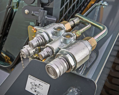
“A very important feature which is standard on Volvo skid steers is the case drain on the auxiliary block and the pressure relieving by simply pushing in the quick-connect couplers on the manifold which simply vents pressurized oil in the main lines to the tank. This is a very well-liked feature to ease the hookup of hydraulic lines,” says Scotese.
In order to further prevent contamination, make sure to follow the OEM’s service interval for hydraulic filter replacement. This may fall anywhere between 500 to 1,000 hours depending on manufacturer and operating conditions. A plugged up hydraulic filter may cause a variety of issues such as loss of speed or power, overheating of the hydraulic oil and damage of components. What type of hydraulic oil should be used in your loader?
Just as important as the type of hydraulic oil used is the amount in the tank. The operator’s manual will show where the level should be within the sight glass and where the boom and bucket should be located while checking the hydraulic oil level. Most machines should be checked on a level surface while having the boom all the way down and the bucket flat on the ground. Hydraulic oil should be checked daily, if not before every time the machine is operated. If the level is low, look around carefully for leaks. Given the dusty and dirty conditions that skid steer loaders and compact track loaders operate in, it is not uncommon for debris to damage the hydraulics and thus affect things like “feeding speed.”
“Brushcutting and cold planing are a couple examples of demanding applications on a hydraulic system,” says Wake. “Both can use 100 percent power at nearly 100 percent of the time. In demanding applications like this, the key to maximum production is feeding speed. Feeding the attachment at a rate to use 100 percent of the power — but not exceeding it to the point the engine bogs, the attachment slows greatly or the attachment stops — will give the most production with the least demand on the machine and operator. A feed pace with the engine pulling a few hundred rpm off peak, tends to be the sweet spot.”
The accumulation of debris from an application like brush cutting can harm the hydraulic cooler. The oil cooler might use engine coolant or outside air to cool the oil. It is vital that the oil remain within the acceptable operating temperature range. Make sure the oil cooler is free of debris and the cooling fins are fairly straight. “John Deere has an electronically controlled hydraulic fan that can vary the speed based on the required cooling,” says Wood. “It’ll also automatically reverse at a set interval to expel the debris built up on the coolers to help limit the number of times you actually have to physically clean out the cooling package.”
Another common way for contamination to enter the hydraulic system is by using hydraulically powered attachments. Before connecting any of the auxiliary hoses, be sure to wipe off the connectors to get rid of any water, dust or other debris. If an attachment was used on a loader that had a hydraulic failure and spread contamination into the attachment, that contamination may enter the next machine it’s connected to.
“That’s probably one of the more concerning things,” says Gregg Zupancic, product marketing manager of skid steers and compact track loaders with John Deere Construction and Forestry. “When you rent attachments, the question is: Who rented that machine last, and what types of materials are in their hydraulic systems and sitting in that attachment unused for a long period of time? That’s why you do things like hydraulic fluid sampling.”
The Cool Flow hydraulic oil cooler from Loftness Specialized Equipment greatly reduces the risk of overheating in skid steers and hydraulically powered attachments when operating in demanding applications and hot work environments. The automatic thermostat-controlled fan provides adequate cooling to the system whenever needed to boost machine efficiency, even when an attachment is not being used. Unlike most other hydraulic coolers that are mounted near the attachment, the Cool Flow attaches to the roof of a skid steer cab where it is less susceptible to vibration, back pressure, debris and potential impact damage. It is specially engineered to allow full hydraulic flow to the attachment in either direction without risk of damage to the cooler. The Cool Flow has up to 40-gpm flow capacity and is compatible with all brands of skid steers.Concentric, Danfoss, Eaton, home, John Deere, March 2016 Print Issue, Parker Hannifin, Rexroth, Turolla, Volvo Construction Equipment

It"s vital that your skid steer keeps rolling, and your hydraulic motors are the key! In this Shop Talk blog post, we are going to talk about 5 signs that your skid steer hydraulic motors need service. We"ll also talk about what those signs could mean, and how to make sure that the problem is with your final drive hydraulic motor and not some other part of your skid steer.
If your final drive trouble with either the seals or the bearings. Failure of either of these parts can lead to a domino effect of disaster, resulting in a totaled hydraulic motor that needs to be replaced.
If your Worn out bearings can lead to serious damage inside your hydraulic motor. You can see in the picture below an example of the aftermath of a bearing failure. This type of damage really can"t be repaired -- you can"t fix chewed up metal.
If you or an operator notices excessive vibration and noise, it would probably be a good time to get your hydraulic motor serviced. You don"t want to wait until the damage reaches the point that the entire final drive motor has to be replaced.
A final drive that refuses to turn is a problem, but it doesn’t necessarily have to do with your hydraulic motor. If the drive motor isn’t turning, check that the
The same information applies to a skid steer that keeps steering to one side, except that means that it’s just one of the hydraulic motors lacking power. The motor with the problem will be on the same side that the skid steer is veering.
Your hydraulic motors are literally what keeps your skid steer rolling, so if you have any of these signs be sure to get it serviced before the problems develop into something that can’t be repaired. These signs mean there is
is your partner in providing new or remanufactured final drive hydraulic motors from a single mini-excavator to a fleet of heavy equipment. Call today so we can find the right final drive or hydraulic component for you, or check out our online store to.

Whether gear, vane, or piston pump, there may come a time when you have to replace your hydraulic pump. When your equipment isn’t working properly and you have narrowed the problem down to a hydraulic pump that needs to be replaced, what do you need to know?
The pump may simply be worn out—they do have a natural lifespan, as they are a wearable item in a hydraulic system. Although it is not possible to give an average lifespan given the different types of pumps and widely varying hours of operation; in general, you can expect many years of good operation from a hydraulic pump in most truck-mounted hydraulic systems. However, the life of a hydraulic pump might be much longer than what you are experiencing. Here are some questions you should ask:
Has the equipment been operating acceptably with this pump for a number of years without incident, and has the decline in performance been gradual over a longer period of time?
In this case, you’ll need to get the pump make and model number so that you can make sure that your replacement will be correct—either with an exact replacement or with another make that has the same operating specifications.
In any case, when replacing a failed hydraulic pump you will want to make sure to use this opportunity to also change out your hydraulic fluid (or at the very least use a filter cart and filter your oil). In the process of failing, your pump has introduced contaminants into your hydraulic system that you want to remove before they damage your new pump or any other hydraulic component. You will want to change your filter element(s) when you install your new pump, and then change it (them) out after a break-in period on your new pump.
If not, then let’s make sure there is not something else going on, or you may just find yourself replacing pumps frequently because the underlying problem hasn’t been addressed.
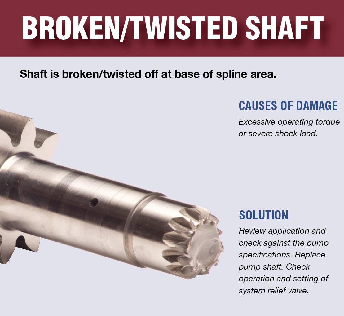
Input shaft is twisted/bcanroken: This occurs due to an extreme shock load to the pump. Typically, this happens when a relief valve is missing from the system, not functioning correctly, set to a much higher value than what the pump can withstand, or is too small for the system flow and thus cannot function correctly.
Shaft fretting:Fretting corrosion occurs under load in the presence of repeated relative surface motion, for example by vibration. Direct mount pump splines can be worn away. The solutions include:
Using larger pump and PTO shafts will not eliminate fretting, but may resolve the problem because of the increased metal available before the failure occurs.
Make sure that the pump is able to get a good flow of oil from the reservoir—pumps are designed to have the oil feed pushed to the pump by gravity and atmospheric pressure, not by “sucking” oil. If the oil level in the reservoir is lower than the inlet of the pump, or the run too long or uphill, oil may not flow adequately to the pump. You can check if the pump is receiving oil adequately by using a vacuum gauge at the pump inlet. For a standard gear pump, at maximum operating RPM, the gauge should read a maximum of 5 inches HG. Larger numbers will damage a gear pump, and if you have a piston pump, the maximum number will be lower for good pump life.
Over pressurization: Pressure relief settings may have been adjusted or changed, and are now higher than what the pump can withstand without causing damage.
Pumps don’t produce pressure, they produce flow and are built to withstand pressure. When the system pressure exceeds the pump design, failure begins—either gradually or catastrophically.
When installing the new pump, back all the relief settings off. Then with the use of a pressure gauge T’d in at the pump outlet, gradually adjust the pressure relief setting until a cylinder or motor begins to move. Once the cylinder has reached the end of its stroke, gradually increase the pressure relief setting until reaching the max system pressure (which would be the pressure rating of the lowest rated component in the system). Sometimes, if a pump has been replaced and is larger than the original (produces more flow), the relief may not be able to allow all the flow being produced to escape back to tank. When that happens, the relief valve is “saturated” and the effect is the same as having no relief in the system. Pressures can reach levels much higher than the relief settings and components can be damaged or destroyed.
Contamination: Over time, the system oil has gotten dirty or contaminated and no longer is able to lubricate the pump, or is carrying contamination to the pump.

The second leading cause of hydraulic pump failure, behind contamination, is cavitation. Cavitation is a condition that can also potentially damage or compromise your hydraulic system. For this reason, understanding cavitation, its symptoms, and methods of prevention are critical to the efficiency and overall health of not just your hydraulic pump, but your hydraulic system as a whole.
The product of excessive vacuum conditions created at the hydraulic pump’s inlet (supply side), cavitation is the formation, and collapse of vapors within a hydraulic pump. High vacuum creates vapor bubbles within the oil, which are carried to the discharge (pressure) side. These bubbles then collapse, thus cavitation.
This type of hydraulic pump failure is caused by poor plumbing, flow restrictions, or high oil viscosity; however, the leading cause of cavitation is poor plumbing. Poor plumbing is the result of incorrectly sized hose or fittings and or an indirect (not straight or vertical) path from the pump to the reservoir. Flow restrictions, for example, include buildup in the strainer or the use of an incorrect length of hose or a valve that is not fully open. Lastly, high oil viscosity—or oil that is too viscous—will not flow easily to the pump. Oil viscosity must be appropriate for the climate and application in which the hydraulic pump is being used.
The greatest damage caused by cavitation results from the excessive heat generated as the vapor bubbles collapse under the pressure at the pump outlet or discharge side. On the discharge side, these vapor bubbles collapse as the pressure causes the gases to return to a liquid state. The collapses of these bubbles result in violent implosions, drawing surrounding material, or debris, into the collapse. The temperature at the point of implosion can exceed 5,000° F. Keep in mind that in order for these implosions to happen, there must be high vacuum at the inlet and high pressure at the outlet.
Cavitation is usually recognized by sound. The pump will either produce a “whining” sound (more mild conditions) or a “rattling” sound (from intense implosions) that can sound like marbles in a can. If you’re hearing either of these sounds, you first need to determine the source. Just because you hear one of these two sounds doesn’t guarantee that your hydraulic pump is the culprit.
To isolate the pump from the power take-off (PTO) to confirm the source, remove the bolts that connect the two components and detach the pump from the PTO. Next, run the PTO with no pump and see if the sound is still present. If not, it is safe to assume your hydraulic pump is the problem.
Another sign you may be experiencing cavitation is physical evidence. As part of your general maintenance, you should be inspecting and replacing the hydraulic oil filter"s elements at regular intervals based on the duty cycle of the application and how often it is used. If at any time during the inspection and replacement of these elements you find metallic debris, it could be a sign that you’re experiencing cavitation in the pump.
The easiest way to determine the health of your complete hydraulic circuit is to check the filter. Every system should have a hydraulic oil filter somewhere in-line. Return line filters should be plumbed in the, you guessed it, return line from the actuator back to tank—as close to the tank as possible. As mentioned earlier, this filter will have elements that should be replaced at regular intervals. If you find metallic debris, your pump could be experiencing cavitation. You’ll then need to flush the entire system and remove the pump for inspection.
Conversely, if you’ve already determined the pump to be damaged, you should remove the filter element, cut it open, and inspect it. If you find a lot of metal, you’ll need to flush the entire system and keep an eye on the other components that may be compromised as a result.
Once cavitation has been detected within the hydraulic pump, you’ll need to determine the exact cause of cavitation. If you don’t, cavitation can result in pump failure and compromise additional components—potentially costing you your system.
Since the pump is fed via gravity and atmospheric pressure, the path between the reservoir and the pump should be as vertical and straight as possible. This means that the pump should be located as close to the reservoir as is practical with no 90-degree fittings or unnecessary bends in the supply hose. Whenever possible, be sure to locate the reservoir above the pump and have the largest supply ports in the reservoir as well. And don"t forget, ensure the reservoir has a proper breather cap or is pressurized (3–5 PSI), either with an air system or pressure breather cap.
Be sure the supply line shut-off valve (if equipped) is fully open with no restrictions. This should be a “full-flow” ball valve with the same inside diameter (i.d.) as the supply hose. If feasible, locate a vacuum gauge that can be T’d into the supply line and plumb it at the pump inlet port. Activate the PTO and operate a hydraulic function while monitoring the gauge. If it reads >5 in. Hg, shut it off, and resume your inspection.
A hose with an inner bladder vulcanized to a heavy spiral is designed to withstand vacuum conditions as opposed to outward pressure. The layline will also denote the size of the hose (i.d.). You can use Muncie Power’s PPC-1 hydraulic hose calculator to determine the optimal diameter for your particular application based on operating flows.
Another consideration, in regards to the inlet plumbing, is laminar flow. To reduce noise and turbulence at the pump inlet, the length of the supply hose should be at least 10 times its diameter. This means that any type of shut-off valve or strainer at the reservoir should be at least 10 diameters from the pump inlet. A flared, flange-style fitting at the pump inlet can also reduce pump noise by at least 50 percent compared to a SAE, JIC, or NPT fitting.
Selecting the proper viscosity of hydraulic fluid for your climate and application is also critical. Oil that is too viscous will not flow as easily to the pump. Consult your local hydraulic oil supplier for help selecting the optimal fluid viscosity.
By maintaining a regular maintenance schedule, remaining vigilant for any signs or symptoms, and taking preventative measures, the good news is that you should be able to prevent cavitation and experience efficient operation for the duration of your pump’s lifespan.
Poor plumbing is the leading cause of cavitation and can be prevented by selecting a properly sized hose, choosing the appropriate fittings, ensuring the most direct, straight routing from the pump to the reservoir, etc.

You can use multiple different upgrades and tuning methods on hydraulic systems. Many users will invest in upgrades that promise more flow and speed. The issue with these upgrades is that they"re not always fit for the hydraulic systems they"re applied to.
Since everything needs to stay in balance, you must make sure your upgrades match the entirety of your hydraulic system. For example, a higher flow pump can help give increased capabilities to a hydraulic system, but did you also check to see if the system"s hoses and piping can handle that increase in flow?
The increased flow can hit your smaller hoses hard and require more pressure just to get through them. This goes for any part of the hydraulic system that isn"t readily capable of handling more flow.
When you make upgrades, also ascertain if you need to change other components. In the example of the higher flow pump, you can simply increase your hose size, and that makes all the difference.
Remember, this is when hydraulic lock occurs, and drift comes to a standstill. That is, unless fluid can seep from the cylinder or the cylinder’s circuit.
Given the nature of how hydraulic drift occurs, you’ll appreciate why a pressure gauge is helpful in diagnosing the cause. You should troubleshoot using pressure testing under controlled conditions.
Even if this happens, it’s not always the reason for hydraulic drift. If your ports are unblemished and the cylinder is full of hydraulic oil, the cylinder will maintain its load without a hitch. That is, until a leak happens at the rod seal.
When a leak is not obvious, use the pressure gauges on the cylinder. A hydraulic fluid leak reduces the cylinder’s effective area. As the pressure increases on the rod side, so, too, must the pressure in the piston side. This will ensure the same load is maintained.
Once you achieve equalization, you stop further drift and hydraulic lock from happening again, until more hydraulic fluid leaks occur. Note, some port relief valves prevent a cylinder from reaching equal pressure. This is due to set lower pressure levels. So in the example we just gave, hydraulic drift will continue as overall pressure hits 2500 PSI.
A case drain is a specific component of a hydraulic system, its objective is to extend the life of a system and reduce time spent on repairs and maintenance.An unrestricted case-drain line is essential on a piston-type hydraulic motor, whether it has axial, radial or bent-axis design. Most skid steers rely on hydraulic systems to power their front loading arms.
A case drain will have an in-line case drain filter to prevent contaminants from travelling from the hydraulic motor to the tank. Operating a skid steer without a case drain line could result in a full system failure as the shaft seal will be irreparably blown out, if not installed properly your hydraulic line will not work and in worst cases become damaged beyond repair.
A good case drain makes your hydraulic system more energy efficient and lowers the pressure on the tank, good general maintenance of your hydraulic system results in longer durability for your skid steer and attachments.
To remove the filter make sure to plug the drain lines to avoid losing hydraulic fluid or introducing contamination into the system. Simply unscrew the hex nut to access the filter element.
Sintering can determine a filter’s porosity which affects what goes through the filter and what doesn’t. Once sintered, the filter is now porous enough to allow hydraulic fluid to flow through it, yet remains dense enough to capture contaminants like metal and rubber debris which will eventually lead to a total system failure if left unmaintained.
Filters in a hydraulic system maintain fluid cleanliness at a level that maximizes component life. The appropriate cleanliness level is based on factors such as operating pressure and the internal clearances of components within a system.
If your case drain filter is blocked, then the hydraulic pressure of the motor will increase severely which will eventually lead to a myriad of mechanical and hydraulic issues and even a total system failure. Seals can be blown allowing hydraulic fluid and lubricant to leak out and also allowing contaminants to make their way into the skid steer and damage it irreparably.
If the filter in your case drain is no longer bronze in colour and looks mucky or dirty we suggest that you replace it. If your case drain is blocked then its worth dissembling the other filters and drain on the hydraulic system to ensure they have remained clean. It’s highly discouraged to attempt to clean your case drain or its filter.
Even if you had power tools or a heavy duty wire brush you will only move more trapped solids into the filter, clogging it even further. Case drain replacements are cheap when compared to replacing your whole final drive. Case drain maintenance is a key part of maintaining the life of your skid steer, and is often overlooked.
The main disadvantage of installing a filter on your hydraulics system is that back pressure created by the filter can cause total system failure caused by excessive pressure on the case drain if installed improperly
Oftentimes, if a vehicle doesn’t already have a case drain line fitted, the manufacturer will not necessarily outline the need for hydraulic fluid to be returned to the tank. If you want optimum reliability from your tank and hydraulics then fitting a case drain line is the way to go.
Case drain lines are a very specific component, its use is debated among hydraulics experts - some say you need a case drain and others suggest you don’t. Ultimately, understanding how a case drain works is fundamental to upholding your machines maintenance and making sure that your tools last for a long time.
Many system failures in hydraulics are caused by leaks from the tank. It’s important not to neglect your hydraulics system as it could put you, or your workers, at risk.
Once you know how case drain filters work and what their function is within the hydraulic system of a skid steer, then you can visit your mechanical professional and ask for their opinion on whether you need to install a case filter on your skid steer or not.

A variety of factors within the system could produce such a vacuum. When fluid enters the hydraulic pump and is compressed, the small air bubbles implode on a molecular level. Each implosion is extremely powerful and can remove material from the inside of the pump until it is no longer functional. Cavitation can destroy brand new pumps in a matter of minutes, leaving signs of physical damage including specific wear patterns. The process of cavitation destroying a hydraulic pump also has a distinctly audible sound similar to a growl.
The good news is that cavitation need not be a common problem in hydraulic systems. A few design flaws are largely responsible for causing cavitation: improper configuration of pump suction lines and the use of suction-line filters or strainers. To prevent these causes of cavitation and ensure the creation of a quality hydraulic system with a long, productive life, seven design elements must be properly executed:
In addition to improper pump suction-line configurations, suction-line filters or strainers can be a leading cause of cavitation. These filters are often placed under the oil reservoir, and thus are rarely serviced properly due to their inconvenient location. With this configuration, the entire reservoir has to be drained and disassembled in order to the reach the filter, so this necessary task is often neglected. As the filter becomes increasingly full of debris over time due to a lack of regular maintenance, not enough fluid will flow to the pump, and cavitation will occur.
Such causes of cavitation can be prevented using a series of correct design practices based on the specific needs and functions of a hydraulic system. Many systems are unique, so an experienced engineer with a firm grasp on each of these concepts must ensure the proper installation and maintenance of a hydraulic system.
Air bubbles in hydraulic fluid first originate is in the reservoir. New oil being introduced into the reservoir can cause turbulent flow, stirring up the oil and introducing air into the fluid, which can lead to cavitation. A correctly designed reservoir tank will prevent this issue.
The size of the tank and the amount of fluid that needs to rest before being extracted depends on the amount of system flow. However, a minimum 4 to 1 tank capacity to flow rate ratio is recommended — four times the oil available in the reservoir at any given time than is needed for extraction to send to the pump. This ensures that the pump will receive clean oil and the oil spends enough time in the reservoir for air bubbles and impurities to work their way out.
Beyond properly designing the reservoir itself, it’s important to include the correct accessories to ensure proper functionality. The breather filter is perhaps the most important accessory for maintaining the correct conditions for the hydraulic fluid in the tank.
When fluid is drawn from the reservoir by the pump, and an equal amount isn"t returned, the oil level will drop. To regulate the pressure and prevent forming a vacuum, air needs to be introduced to the tank to occupy the extra volume created upon removal of the oil. A breather filter performs this function, which helps avoid cavitation.
Incorrect design and configuration of suction lines is the primary cause of cavitation in hydraulic systems. For this reason, it’s crucial to use correct design practices when designing the suction lines, such as using the proper line size, minimizing fittings on the line, and properly sizing the ball valve to handle the amount of flow through the line.
The size of a suction line should be large enough for the liquid’s area to flow through at the correct rate and in the correct amount. Because the pump needs to be constantly supplied with oil, it becomes obvious how a line that’s too small could prevent this essential function. The exact specifications of a suction line in terms of length and width can’t be determined in a general sense — it requires a skilled engineer with a firm grasp of the process to make the correct decision on this specification.
Another best practice to consider when configuring suction lines is to include a lock on the suction ball valve, preventing it from being accidentally closed or left partially closed during the pump’s operation. Shutting off the flow of a suction line during pump operation will have cataclysmic effects on the system.
For example, the oil can be filtered upon entering the reservoir tank rather than when leaving the tank. Or a off-line (kidney loop) filtration system can be used to pull the oil out of the tank, filter it, and reinsert it before it’s extracted and sent to a hydraulic pump. These solutions allow for greater ease of maintenance and lower the chance of system failure.
A key aspect of a hydraulic system is a pump that’s properly sized to handle the flow rate and amount of fluid in the system. Again, this decision must be made by an experienced engineer with a good understanding of the entire process. A pump’s size can be determined by incorporating several variables of the process into a standard equation while also considering unique application conditions.
Another key element within a hydraulic system is to maintain the proper fluid temperature. If the hydraulic fluid gets too cold, it can become too viscous, increasing pressure drop in fluid lines and eventual cavitation in the pump. On the other hand, overheated hydraulic fluid can become too thin, compromising its ability to lubricate the hydraulic pump.
To regulate the temperature of the fluid, electric heating elements can be placed in the reservoir to keep the fluid at the ideal temperature of 110°F. Hydraulic systems often heat themselves naturally, so it’s also important to monitor for temperatures in excess of 110° and provide a heat exchanger or operate the system at reduced capacity.
Most systems use a flooded suction design, meaning that the pump is placed below the oil level to achieve net positive suction. The oil comes out of the reservoir above the location of the pump, which means gravity is used to assist in creating pressure into the pump and suction line. This represents the ideal configuration for a pump in a hydraulic system.
The alternative to this layout is non-flooded suction, in which the pump is placed on top of the tank. This configuration is often used to save space in a system with a limited footprint, but results in several disadvantages. For instance, the pump has to perform the extra work of pulling the oil up against gravity to create a vacuum and then pump the fluid out, which inherently creates restrictions by working against gravity. Also, certain types of pumps will function poorly in a non-flooded suction layout. In these cases, a charge pump can be used to provide positive pressure in the pump suction line.
If each of these design elements is carefully considered while engineering a hydraulic system, the risk of cavitation damaging or destroying hydraulic pumps should decrease significantly. Latest from Valin"s Blog

When it comes to the repair and maintenance of hydraulic systems, there are certain hydraulic equipment mistakes that occur more often than others. Whether it is changing hydraulic filters too often or using the wrong type of hydraulic fluid, these errors can lead to serious problems such as unnecessary maintenance costs, increased repair costs, system downtime, premature wear of components, and even catastrophic failure.
Hydraulic fluid is expensive, and changing it before it actually needs to be changed wastes money, results in more system downtime than is necessary, and can even increase the risk of hydraulic contamination – none of which are good for the system or for your bottom line.
Many hydraulic systems come with manufacturer recommendations as to how often the hydraulic oil should be changed, and these recommendations are meant to serve more as guideline than a hard and fast rule. Most recommendations are based on service hours, but there are many other variables that can affect when your hydraulic fluid needs to be changed, such as:
In fact, heat, water, and contamination are the three key factors in shortening the life of your hydraulic fluid. The only accurate way to determine when hydraulic fluid needs to be changed is to perform an analysis on fluid samples, preferably from different points in the system.
If you maintain your hydraulic system well, you will discover that the hydraulic fluid lasts much longer and may only need to be replaced when the additives have been depleted. Most hydraulic contamination can be removed through off-line filtering, and a system that is carefully maintained will not have major issues with overheating and accelerated degradation. In short, the better maintained your hydraulic equipment is, the longer your hydraulic fluid is going to last.
Using the wrong hydraulic oil in your system is one of the more common hydraulic equipment mistakes. When it comes to the type of hydraulic fluid you use, it is important to keep in mind that it serves a variety of purposes: it transmits power through the system, lubricates parts within the system, prevents oxidation, and helps to conduct generated heat away from critical components. Failure to use the correct proper oil will not only decrease the efficiency and performance of the hydraulic system, but it can also seriously shorten the life of the system and the many components that comprise it.
The key to selecting the right hydraulic oil lies in the viscosity of the fluid. If the viscosity of the hydraulic fluid is too high, it will not be able to fully lubricate the hydraulic components during a cold start, which can lead to premature wear. In addition, higher viscosity hydraulic fluid will result in system power losses due to increased fluid friction, which in turn reduces the overall efficiency of your system while increasing its power consumption.
On the other hand, if the viscosity is too low, then the components will not be adequately protected during operation. This will result in increased wear and, over time, premature failure of key components such as hydraulic pumps and motors. It also leads to generated contamination, which can cause even more efficiency losses and accelerated wear.
Because of the factors tied to viscosity, we can see that there is more to selecting the correct hydraulic fluid than simply following manufacturer recommendations. With viscosity being on


 8613371530291