
swash plate hydraulic pump animation free sample

the advantage of the first type is it simplicity and efficiency, driving a light swash plate requires less power than the heavy block of barrel and pistons
The key advantage of the axial design is that the cylinders are arranged in parallel around the output/crank shaft in contrast to radial and inline engines, both types having cylinders at right angles to the shaft. As a result, it is a very compact, cylindrical engine, allowing variation in compression ratio of the engine while running. In a swashplate engine the piston rods stay parallel with the shaft, and piston side-forces that cause excessive wear can be eliminated almost completely. The small-end bearing of a traditional connecting rod, one of the most problematic bearings in a traditional engine, is eliminated.
An alternative design, the Rand cam engine, replaces the plate with one or more sinusoidal cam surfaces. Vanes mounted parallel to a shaft mounted inside a cylindrical "barrel" that are free to sliding up and down ride the sinuous cam, the segments formed by rotor, stator walls and vanes constituting combustion chambers. In effect these spaces serving the same purpose as the cylinders of an axial engine, and the sinuous cam surface acts as the face of the pistons. In other respect this form follows the normal cycles of internal combustion but with burning gas directly imparting a force on the cam surface, translated into a rotational force by timing one or more detonations. This design eliminates the multiple reciprocal pistons, ball joints and swash plate of a conventional "barrel" engine but crucially depends on effective sealing provided by sliding and rotating surfaces.[1]
(A wobble-plate is similar to a swash plate, in that the pistons press down on the plate in sequence, imparting a lateral moment that is translated into rotary motion. This motion can be simulated by placing a compact disc on a ball bearing at its centre and pressing down at progressive places around its circumference. The difference is that while a wobble plate nutates, a swash-plate rotates.
In 1911 the Macomber Rotary Engine Company of Los Angeles marketed one of the first axial internal-combustion engines, manufactured by the Avis Engine Company of Allston, Massachusetts. A four-stroke, air-cooled unit, it had seven cylinders and a variable compression ratio, altered by changing the wobble-plate angle and hence the length of piston stroke.
In 1913 Statax-Motor of Zürich, Switzerland introduced a swashplate engine design. Only a single prototype was produced, which is currently held in the Science Museum, London. In 1914 the company moved to London to become the Statax Engine Company and planned on introducing a series of rotary engines; a 3-cylinder of 10 hp, a 5-cylinder of 40 hp, a 7-cylinder of 80 hp, and a 10-cylinder of 100 hp.
In 1917 Anthony Michell obtained patents for his swashplate engine design. Its unique feature was the means of transferring the load from the pistons to the swashplate, achieved using tilting slipper pads sliding on a film of oil. Another innovation by Michell was his mathematical analysis of the mechanical design, including the mass and motion of the components, so that his engines were in perfect dynamic balance at all speeds.
In 1920 Michell established the Crankless Engines Company in Fitzroy (Australia), and produced working prototypes of pumps, compressors, car engines and aero engines, all based on the same basic design.
The Bristol Axial Engine of the mid-1930s was designed by Charles Benjamin Redrup for the Bristol Tramways and Carriage Company; it was a 7-litre, 9-cylinder, wobble-plate type engine. It was originally conceived as a power unit for buses, possibly because its compact format would allow it to be installed beneath the vehicle"s floor. The engine had a single rotary valve to control induction and exhaust. Several variants were used in Bristol buses during the late 1930s, the engine going through several versions from RR1 to RR4, which had a power output of 145 hp at 2900 rpm. Development was halted in 1936 following a change of management at the Bristol company.
Perhaps the most refined of the designs was the British Wooler wobble-plate engine of 1947. This 6-cylinder engine was designed by John Wooler, better known as a motorcycle engine designer, for aircraft use. It was similar to the Bristol axial engine but had two wobble-plates, driven by 12 opposed pistons in 6 cylinders. The engine is often incorrectly referred to as a swashplate engine.
A classical, Spanish built design, parallel pistons working in opposition, sine-wave swashplate, in 2023 with two versions, a car sized, with liquid cooling, as prototype, and an air cooled four cylinder, 125 cc, 22 HP, 4.5 kg unit, aimed at drones and big aeromodels, in pre-production stage. [2]
The Cylindrical Energy Module (CEM) is a sine-wave swashplate engine that can also be used as a standalone pump, powered by an external source. The rotating swashplate rotor assembly is moved back and forth with the help of piston drive pins, which follow a stationary sinusoidal cam track that encircles the rotor assembly.
The most well-known application is in torpedoes, where the cylindrical shape is desirable. The modern Mark 48 torpedo is powered by a 500 hp swashplate engine geared to a pump-jet propulsor. It is fueled by Otto fuel II, a monopropellant that requires no oxygen supply and can propel the torpedo at up to 65 knots (120 km/h) (74.56 mph).
Other applications include pneumatic and hydraulic motors, hydrostatic transmissions such as Honda"s Hondamatic CVT,air conditioner pumps.Stirling engines use a swashplate arrangement, e.g., Stirling Thermal Motors" STM 4-120 engine.

In these pumps, the displacement bodies are not arranged radially, but parallel to the axis of rotation of a cylinder drum. The conversion of the drive movement from the engine to the stroke movement of the pistons differs depending on the design. There are two principles:
During the suction phase, the pistons move out of the barrel. Liquid flows into the piston chamber via the control plate with control slots. As the rotation continues, the pistons on the opposite side move back into the drum. The liquid is thus displaced to the pressure port via a further control slot.
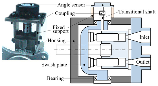
In contrast to the swash plate design, the stroke movement of the pistons is achieved by the inclined position of the cylinder drum to the drive shaft.
In contrast to the axial piston pump, the working pistons of the Radial Piston Pump are arranged radially and star-shaped to the drive shaft. The conveying or lifting movement of each individual working piston/displacer is caused by an eccentric located on the pump shaft or an external eccentric.
There are two types of construction: A radial piston pump pressurized from the outside when the working chamber is filled from "the outside" and the radial piston pump pressurized from "the inside" when the cylinders are filled from the inside (via a hollow shaft).
An axial piston pump is a positive displacement pump that has a number of pistons in a circular array within a hydraulic motor or an automotive air conditioning compressor.
An axial piston pump has a number of pistons (usually an odd number) arranged in a circular array within a housing which is commonly referred to as a cylinder block, barrel. This cylinder block is driven to rotate about its axis of symmetry by an integral shaft that is, more or less, aligned with the pumping pistons (usually parallel but not necessarily).
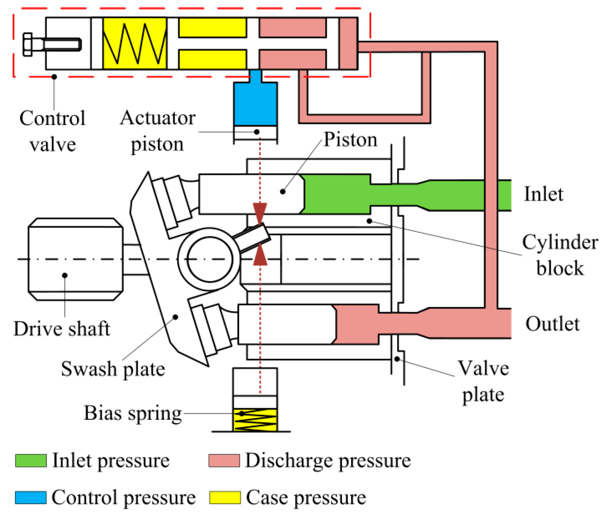
Mating surfaces. One end of the cylinder block is convex and wears against a mating surface on a stationary valve plate. The inlet and outlet fluid of the pump pass through different parts of the sliding interface between the cylinder block and valve plate. The valve plate has two semi-circular ports that allow inlet of the operating fluid and exhaust of the outlet fluid respectively.
Protruding pistons. The pumping pistons protrude from the opposite end of the cylinder block. There are numerous configurations used for the exposed ends of the pistons but in all cases they bear against a cam. In variable displacement units, the cam is movable and commonly referred to as a yoke or hanger. For conceptual purposes, the cam can be represented by a plane, the orientation of which, in combination with shaft rotation, provides the cam action that leads to piston reciprocation and thus pumping. The angle between a vector normal to the cam plane and the cylinder block axis of rotation, called the cam angle, is one variable that determines the displacement of the pump or the amount of fluid pumped per shaft revolution. Variable displacement units have the ability to vary the cam angle during operation whereas fixed displacement units do not.
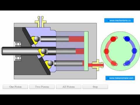
Reciprocating pistons. As the cylinder block rotates, the exposed ends of the pistons are constrained to follow the surface of the cam plane. Since the cam plane is at an angle to the axis of rotation, the pistons must reciprocate axially as they precess about the cylinder block axis. The axial motion of the pistons is sinusoidal. During the rising portion of the piston"s reciprocation cycle, the piston moves toward the valve plate. Also, during this time, the fluid trapped between the buried end of the piston and the valve plate is vented to the pump"s discharge port through one of the valve plate"s semi-circular ports - the discharge port. As the piston moves toward the valve plate, fluid is pushed or displaced through the discharge port of the valve plate.
Effect of precession. When the piston is at the top of the reciprocation cycle (commonly referred to as top-dead-center or just TDC), the connection between the trapped fluid chamber and the pump"s discharge port is closed. Shortly thereafter, that same chamber becomes open to the pump"s inlet port. As the piston continues to precess about the cylinder block axis, it moves away from the valve plate thereby increasing the volume of the trapped chamber. As this occurs, fluid enters the chamber from the pump"s inlet to fill the void. This process continues until the piston reaches the bottom of the reciprocation cylinder - commonly referred to as bottom-dead-center or BDC. At BDC, the connection between the pumping chamber and inlet port is closed. Shortly thereafter, the chamber becomes open to the discharge port again and the pumping cycle starts over.
Variable displacement. In a variable displacement pump, if the vector normal to the cam plane (swash plate) is set parallel to the axis of rotation, there is no movement of the pistons in their cylinders. Thus there is no output. Movement of the swash plate controls pump output from zero to maximum. There are two kinds of variable-displacement axial piston pumps:
direct displacement control pump, a kind of axial piston pump with a direct displacement control. A direct displacement control uses a mechanical lever attached to the swashplate of the axial piston pump. Higher system pressures require more force to move that lever, making direct displacement control only suitable for light or medium duty pumps. Heavy duty pumps require servo control.linkages and springs and in some cases magnets rather than a shaft to a motor located outside of the pump (thereby reducing the number of moving parts), keeping parts protected and lubricated and reducing the resistance against the flow of liquid.
Pressure. In a typical pressure-compensated pump, the swash plate angle is adjusted through the action of a valve which uses pressure feedback so that the instantaneous pump output flow is exactly enough to maintain a designated pressure. If the load flow increases, pressure will momentarily decrease but the pressure-compensation valve will sense the decrease and then increase the swash plate angle to increase pump output flow so that the desired pressure is restored. In reality most systems use pressure as a control for this type of pump. The operating pressure reaches, say, 200 bar (20 MPa or 2900 psi) and the swash plate is driven towards zero angle (piston stroke nearly zero) and with the inherent leaks in the system allows the pump to stabilise at the delivery volume that maintains the set pressure. As demand increases the swash plate is moved to a greater angle, piston stroke increases and the volume of fluid increases; if the demand slackens the pressure will rise, and the pumped volume diminishes as the pressure rises. At maximum system pressure the output is once again almost zero. If the fluid demand increases beyond the capacity of the pump to deliver, the system pressure will drop to near zero. The swash plate angle will remain at the maximum allowed, and the pistons will operate at full stroke. This continues until system flow-demand eases and the pump"s capacity is greater than demand. As the pressure rises the swash-plate angle modulates to try to not exceed the maximum pressure while meeting the flow demand.
Designers have a number of problems to overcome in designing axial piston pumps. One is managing to be able to manufacture a pump with the fine tolerances necessary for efficient operation. The mating faces between the rotary piston-cylinder assembly and the stationary pump body have to be almost a perfect seal while the rotary part turns at perhaps 3000 rpm. The pistons are usually less than half an inch (13 mm) in diameter with similar stroke lengths. Keeping the wall to piston seal tight means that very small clearances are involved and that materials have to be closely matched for similar coefficient of expansion.
The pistons have to be drawn outwards in their cylinder by some means. On small pumps this can be done by means of a spring inside the cylinder that forces the piston up the cylinder. Inlet fluid pressure can also be arranged so that the fluid pushes the pistons up the cylinder. Often a vane pump is located on the same drive shaft to provide this pressure and it also allows the pump assembly to draw fluid against some suction head from the reservoir, which is not an attribute of the unaided axial piston pump.
Another method of drawing pistons up the cylinder is to attach the cylinder heads to the surface of the swash plate. In that way the piston stroke is totally mechanical. However, the designer"s problem of lubricating the swash plate face (a sliding contact) is made even more difficult.
Internal lubrication of the pump is achieved by use of the operating fluid—normally called operating temperature, limited by the fluid, of about 120 °C (250 °F) so that using that fluid as a lubricant brings its own problems. In this type of pump the leakage from the face between the cylinder housing and the body block is used to cool and lubricate the exterior of the rotating parts. The leakage is then carried off to the reservoir or to the inlet side of the pump again. Hydraulic fluid that has been used is always cooled and passed through micrometre-sized filters before recirculating through the pump.
Despite the problems indicated above this type of pump can contain most of the necessary circuit controls integrally (the swash-plate angle control) to regulate flow and pressure, be very reliable and allow the rest of the hydraulic system to be very simple and inexpensive.
Axial piston pumps are used to power the hydraulic systems of jet aircraft, being gear-driven off of the turbine engine"s main shaft, The system used on the F-14 used a 9-piston pump that produced a standard system operating pressure of 3000 psi and a maximum flow of 84 gallons per minute.
Automotive air conditioning compressors for cabin cooling are nowadays mostly based around the axial piston pump design (others are based on the scroll compressor or rotary vane pump ones instead) in order to contain their weight and space requirement in the vehicle"s engine bay and reduce vibrations. They"re available in fixed displacement and dynamically adjusted variable displacement variants.
Piston design - Solid, hollow, or with piston rings. The design and weight of the pistons will have a major effect on pump efficiency. The Parker F11 design with its lightweight head and retained balls can reach significantly higher speeds than swashplate pumps with their longer, heavier pistons.
Some pumps and motors can run over-centre, which means they can provide flow or rotate their drive shaft in both directions. These are commonly used in closed circuit, mobile vehicle drives systems.
Bent axis designs tend to have much heavier duty shaft bearings than swashplate pumps. This is because they are more commonly used as motor drive units and have to take the wheel loads against their shaft. Swashplate pumps, on the other hand, tend to be driven through flexible couplings that will remove any side loads, so the internal bearing is sized just to take the internal loads from the dynamic and pressure loading forces.
Noise level can be an issue with piston pumps. The noise is generated by the discontinuities in the flow e.g. as the pistons move forward and backward they create a pulsating flow that passes into the complete hydraulic system and vibrates or radiates from other components further down the circuit. This flow discontinuity is further complicated by the supply port which connects and disconnects each piston as it rotates. The timing of the opening and closing can create other, higher frequency flow discontinuities. Often different timing plates are available for different operating conditions e.g. fixed speed or variable speed applications.
Case leakage line pressures are critical for controlling the pressure balance of the slipper against the suction pressure. Care should be taken with some pump controllers as the valves exhaust into the pump casing and can create dangerous pressure spikes. Make sure case drain lines are sufficiently sized. One possible solution may be to use a more compliant, clear plastic hose for the case leakage line which will have the effect of damping out these peaks before damage the slippers. Case leakage line temperatures are also a good way of monitoring the health of the pump as discussed in the vane pump section.
If you are in doubt about the most appropriate pump to use in your application then always talk to manufacture or distributor who should be able to offer the most appropriate pump range and advise the expected service life.


 8613371530291