
swash plate hydraulic pump animation brands

Axial piston pumps are a common part throughout construction machines and across construction equipment brands. Their design allows them to be used from the cooling system to the steering system to a multitude of places throughout a machine. Anyone who has worked in construction equipment has certainly come across an axial piston pump, but one might still wonder, “What exactly is going on in this little box?” That’s why we’re here to help.
Whether you’re researching an axial piston pump problem or you’re just inquisitive about this widely-used part, read on for a short explainer on how they work and what they do.
At its most basic, an axial piston pump turns mechanical energy (the turning of a shaft) into hydraulic output (the moving of fluid). The use cases for an axial piston pump are wide-ranging, leading to the adoption of this pump design throughout construction equipment types and across construction equipment brands. An axial piston pump provides advantages in dependability, simplicity, and efficiency leading to its use in handling a wide range of tasks on a machine.
The basic mechanics and design of an axial piston pump are also commonly combined with gearing designs to create axial piston motors. An example is the swing motor commonly found in excavators which combines the design with planetary gears to power the rotation of the house at the point where it spins relative to the tracks.
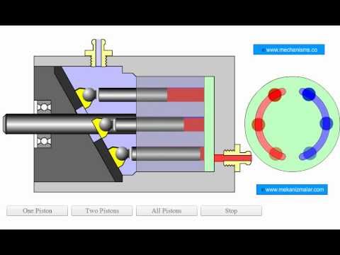
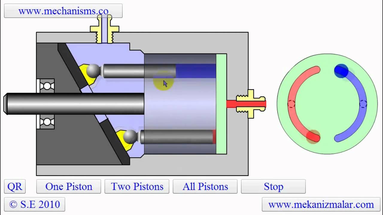
Seeing the rotation of the piston barrel and the back and forth action of the pistons clearly illustrates how the axial piston pump works. » Click video to play/pause animation.
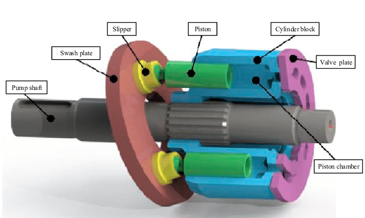
To convert mechanical energy into hydraulic output, an axial piston pump utilizes a rotating, splined drive shaft that connects to and turns a piston barrel. To create the pumping mechanism of the pump, piston pumps can use either a swash plate design (featured in video) or a bent axis design.
In both designs, as the pistons rotate they are repeatedly drawn away from a valve plate and then pushed closer to the valve plate. This variation in distance alters the size of the chamber available to hold hydraulic fluid. At times when the gap between the end of a specific piston and the valve plate is decreasing, the chamber will shorten, and hydraulic fluid will be expelled through the valve plate. As the piston rotates, it will eventually reach a point where the gap is increasing, leading to a longer chamber. This vacuum will cause hydraulic fluid to be drawn into the chamber through the valve plate.
Since the valve plate acts as a divider between the input and output sides of the pump, as the pistons and piston barrel rotate, hydraulic fluid will be continuously cycled through the pump as it is drawn from one connection and directed with force into another.
Since the rotating of the pistons and piston barrel is determined by the rotation of the shaft, the pump"s output can be controlled by increasing and decreasing the speed of the shaft. In the swash plate design, further control of the pump is possible by adjusting the angle of the swash plate, changing the distance of the pistons from the valve plate, and, in turn, increasing or decreasing the size of the chamber available to hold hydraulic fluid.
The shaft distributes mechanical, rotational force to the pump. Splines on the shaft interconnect with splines in the piston barrel to turn the barrel and pistons while splines on the part of the shaft that extends from the housing connect to the machine.
Pistons inside the pump rotate around the center shaft. Since the plane at which one end of the piston is attached is set at an angle determined by the swash plate, the pistons also vary their distance from the valve plate as they rotate. This variation causes a continuous alternation in the depth of the cavity available to hold hydraulic fluid inside the piston barrel and leads to their continuous looping through the pumping process.
In an axial piston pump utilizing a swash plate design, the swash plate is responsible for setting the angle of the piston’s container and, in turn, the amount of variation in depth the pistons will move through. Altering the angle of the swash plate allows the action of the axial piston pump to be further controlled.
The valve plate sits on the end of the piston barrel opposite the pistons. Slots in the valve plate allow fluid to be directed to specific connections for intake and discharge.
Axial piston pumps feature a number of moving parts which always require lubrication and other techniques to decrease friction between moving surfaces. Because of the often rapid speed at which they operate, if an axial piston pump operates in an environment with less than ideal lubrication wear can happen rapidly and even lead to catastrophic failure.
An axial piston pump is often subject to repetitive, long-lasting, and high-pressure work, and with any part subject to those conditions, the buildup of heat over time is always a possibility. Overheating of the pump can be further amplified through inefficiencies developing inside the pump and issues with the overall hydraulic system with which the pump is connected. Examples of each would be: a bearing failure that forces the pump to work harder to maintain expected output and bubbles in the hydraulic fluid inside the pump (cavitation) from operating in a system low in fluid.
Like any part in the hydraulic system, containing hydraulic fluid and directing it in very specific ways is necessary for consistent and expected functioning. If fluid is allowed to flow in unintended ways, the pump will lose efficiency or even lose the ability to provide adequate output. Seals and gaskets are used in axial piston pumps to ensure proper operation, but over time (or due to neglect) seals and gaskets can reach a state of failure that will affect the working ability of the pump.
While a full determination of why an axial piston pump failed can involve a removal and disassembly of the part, often there are simple signs to watch for when one suggests an issue with an axial piston pump, namely:
If the pump begins underperforming during operation and other issues that could affect output like loose hydraulic connections are eliminated, a lack of power can be a sign of internal problems in the pump.
Most axial piston pumps can be expected to create some level of noise, depending on size and design. A pump that has suddenly become louder or begins broadcasting an erratic noise can be a sign that internal parts of the pump are operating outside of proper conditions.
Friction is almost always a byproduct of moving parts and, if unchecked inside the part, it will often show its effects on the outside of the part through heat and/or vibrations. While some heat and vibration is to be expected, especially if the pump is called upon to work for an extended period of time, excess vibration and heating are both a symptom of a problem and a possible escalation of issues.
Most hydraulic systems connect a number of parts in a machine and contamination from failure can often come from any of them. The discovery of fluid contamination can be combined with the previously mentioned signs to narrow issues to the pump.
An H&R tech is at work in the shop rebuilding an axial piston pump, a fairly common sight in the shop because of the wide use of axial piston pumps in construction equipment.
Here’s to hoping you read this article on axial piston pumps because of a pure curiosity about how they work and function. If though, you’ve arrived here in search of a diagnosis for axial piston pump problems, hopefully, with this information in hand you’re closer to solving your troubles.
As a top dismantler and parts rebuilder for construction equipment, axial piston pumps are a frequent rebuild project in the H&R Recon and Rebuild shops. Big parts to small, our parts technicians brings decades of experience to our rebuild project and we take pride in knowing that experience leads to a part that will outlast and outperform the competition. If you’re in search of a replacement axial piston pump, our Parts Specialist are here to help in your search. Just give them a call.
The displacement of a pump is defined by the volume of fluid that the gears, vanes or pistons will pump in one rotation. If a pump has a capacity of 30 cm3, it should treat 30 ml of fluid in one rotation.
In axial piston variable pumps, the flow is proportional to the drive speed and the displacement. The flow can be steplessly changed by adjusting the swivel angle. Axial piston variable ...
... axial piston pump type V60N is designed for open circuits in mobile hydraulics and operate according to the swash plate principle. They are available with the option of a thru-shaft for operating additional ...
Variable displacement axial piston pumps operate according to the bent axis principle. They adjust the geometric output volume from maximum to zero. As a result they vary the flow rate ...
... piston pump type V30D is designed for open circuits in industrial hydraulics and operate according to the swash plate principle. They are available with the option of a thru-shaft for operating additional ...
... circuit axial piston pumps are used as hydrostatic transmission components in self-propelled machines and for rotary drives in both fixed and mobile equipment of all kinds.
... rev. displacements, these pumps are designed to operate in both directions of rotation (clockwise or counter-clockwise). Only one reference regardless of direction of rotation. The TXV indexable pumps ...
... needs of truck hydraulics, the TXV variable displacement pumps with LS (Load Sensing) control allow flow regulation to suit the application requirements. The pump ...
Axial piston twin flow pump. With a very high performance in all job conditions. Due to its twin flow configuration this pump allows a great variety of solutions in different job applications.
Air hydraulic pump, double pneumatic motor, double effect, foot operated with lock-up function, lever distributor valve (4/3), 10L tank, oil flow 8.5 / 0.26 l / min
... customer system options for mechanical, hydraulic and electric input solutions are available. Further special regulating features like torque control and pressure cut-off are also available. The reliable ...
... PVG is a variable-displacement axial-piston pump designed to take on your most demanding applications. It offers high-pressure, superior performance in a compact design ...
Variable displacement pumps in closed loop; 3 basic design units and 8 max. displacement sizes of 14, 18, 21, 28, 35, 46, 56, 64 cc/rev; various control options; max. ...
Parker P2/P3 High Pressure Axial Piston Pumps are variable displacement, swashplate piston pumps designed for operation in open circuit, mobile hydraulic ...
... Series pump offers variable displacement axial piston pumps for open-circuit applications. Featuring a compact footprint and continuous operating pressure ...

Another option is to utilize a load sense compensator. With a load sense compensator, this compensator will include a lighter spring setting to control the swash plate. Upstream pressure is ported into a load sense port on the pump, as the pressure requirement increases, the pressure acts against the load sense piston. Once the pressure requirement is higher than the offset, the pump swash plate angle changes and the pump begins to increase flow, by increasing the swash plate angle, until we have enough pressure to balance the piston. Once balanced, the flow remains steady until the load changes.
The offset pressure is normally 200-300 PSI. With a load sense compensator, the pump produces what the load requires plus the spring offset, normally 200-300 PSI.
This system will also utilize a standard compensator so if the system pressure increases enough, the pressure compensator will take control and reduce the swash plate angle to reduce the pressure.
With a standard pressure compensator, you would have to set the pump at 2600 PSI to accomplish the work. When the work only requires 1500 PSI, the pump will be trying to produce 2600 PSI. Fifty percent of the time, your system will be operating at 1100 PSI of inefficiency, which means heat. With a load sense compensator, when the load requires 1500 PSI, the pump will actually produce about 17-1800 PSI. Yes, this is 300 PSI inefficient, but that is much better than 1100 PSI inefficient.
With a varying load, the load sense is a much better system. For additional control, you can utilize an electronic proportional flow control or throttle. You can use an electrical signal to vary the hydraulic signal which is received by the pump’s load sense line. This would give you full electronic control of the amount of flow the pump produces.
There are additional control options which allow you to remotely control the pressure compensator. With this remote compensator control, you can set 2 or more different system pressures. With the ability of a variable piston pump to build 5,000 or more PSI; the additional setting can be used when operating components with a much lower pressure requirement.
The next control is a torque limiting or HP limiting control. By adding an additional spring and piston, you can set a pump to always maximize its allowable input torque, therefore, maximizing output flow and pressure at a defined setting.
Our pump has an output of 15 CIR, a maximum flow of about 113 gallons at 1750 RPM. Our prime mover is an electric motor, 75HP with a 1.15 service factor. I want to keep my cylinder moving as fast as possible, but I also want to ensure that I never exceed a power demand 82 HP.
At 82 HP, the pump can produce 1254 PSI at full output, 113 GPM. As the load requires more pressure, the pump will begin to reduce flow and increase pressure. At 90 GPM flow, the system will produce about 1560 PSI; at 60 GPM we can get almost 2350 PSI. At 4500 PSI, the pump flow will be reduced to about 31 GPM. The advantage of this pump is that the internal controls of the pump are adjusting to maximize flow and pressure at all times without exceeding the available HP.
If I wanted to use a pump which could produce 113 gallons of flow at 4500 PSI, I would need 296 HP. If I choose a 75 HP motor with a pressure compensated variable piston pump, the motor would stall before the pressure compensator could kick in and reduce the pump flow. Depending on the load, a load sense pump could also stall the 75 HP motor if the load pressure is high enough to use up the HP before the pressure compensator kicks in. With a torque limiting (HP) control, we utilize the full limits of the prime mover and maximize power usage.

In the parts tables below you may select the hydraulic parts you need. All PVplus parts we sell are genuine Parker Hannifin and originate in Germany. We highly recommend to use genuine OEM parts only to ensure smooth operation and longer service life.
The Parker PVplus hydraulic pumps are produced in Chemnitz, Germany and manufactured by Parker Hannifin Manufacturing Germany GmbH & Co. KG. The PV360R1E1T1NMM1 is an axial piston pump of variable displacement with a maximum displacement volume of 360.0 ml/rev. The mounting interface is according to SAE (ISO 3019-1) and the pump control group is hydromechanical control. Further details are listed in the Parker PV360 Datasheet and pump control options.
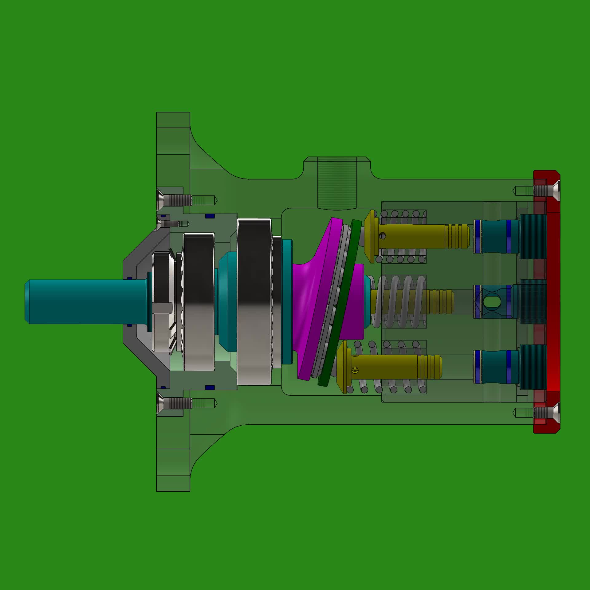
All pump repair kits listed on this page are for Parker PVplus axial piston pumps of latest design series. Current design of Parker PVplus PV360 is 46 Design (hydraulic pump) and 45 Design (pump controller). The item numbers listed in these tables refer to the PV360 exploded view drawing of the Parker PV360 Spare Sparts List PVplus Design 46. Should you require spare parts for an older design PVplus pump, please contact us for further information (do not forget to include pump name plate information).
Be sure to operate the hydraulic pump under optimum oil viscosity (not too low) since a thinner lubrication film causes more direct metal to metal contact resulting in increased wear in glide and roller bearings. The PVplus bearing kit contains both the front and rear roller bearing of the drive shaft and are also included in the pump shaft repair kit. The PVplus trunnion bearing unit contains the two glide bearings of the pump swash plate (trunnion bearings are not included in swash plate kit).
A busted piston pump within your company’s hydraulic system is nothing short of frustrating. Instead of stressing about downtime and replacing the entire unit, choose Global Electronic Services. Our technicians ensure quick hydraulic piston repair services to increase your operation’s uptime and keep everything working at a smooth pace.
After understanding the issues your hydraulic pistons are facing, we replace broken, damaged or worn components and repair failed parts as necessary. Once we make crucial repairs and replacements, we test the hydraulic system to ensure it runs at its highest operating level.
While some faults are more accessible to detect than others, our specialists use top-of-the-line tools in combination with their extensive line of experience to recognize a variety of piston pump complications. Delivering fast, effective and efficient piston pump repair services allows us to provide top-quality solutions.
Hydraulic piston pump repairs from Global Electronic Services help you feel confident in your company’s operations. We pinpoint the hydraulic system’s issues and make fast turnaround times to keep you moving.
Quick turnarounds:Using efficient methods with our years of experience, Global Electronic Services experts can repair your hydraulic piston issues within one to five days. We help ensure your company’s uptime and productivity remain high.
Top-notch repairs:Global Electronic Services offers an 18-month, in-service warranty — giving you peace of mind that you can rely on the equipment. We can tackle any piston faults and other hydraulic concerns.
The first step of repairing your hydraulic piston pump is disassembly. We take apart the axial piston pump for inspection and measurement, recording the dimensions of each part. Once we look through the entire unit and determine its issues, we prepare a quotation to give you an idea of what to expect.
When we get the go-ahead to move on with our repairs, we start by cleaning the unit. We lap the rotary parts and end cover, then make sure the bearing and shaft fit. Our technicians also ensure the pump’s play is within tolerance.
We make the appropriate repairs and replacements of critical parts, then reinstall the rotary components. After we complete the entire process, our specialists test the hydraulic piston pump. If it’s working at peak levels, we calibrate it, then send it off to painting and finishing. If it’s still not up to par, we go back and make corrections.
Repairing and replacing these essential hydraulic piston pump parts is a more economical solution than replacing the entire unit. Although the source of a pump’s failure can come from a multitude of sources, many fall into a few areas, such as:
In many cases, wear and tear cause problems. However, excessive heat, cavitation, extreme pressure and contamination can also cause premature failure of your piston pump. Another reason for failure is from incorrect installation — all of which we can fix on the spot.
We use sophisticated software, digital controls and integrated electronics to restore your company’s piston pumps. Global Electronics Services works with the increasing complexity of hydraulic systems. Our technicians can inspect, repair, test and calibrate a range of piston pump issues.
Global Electronic Services can answer any questions you have about hydraulic piston pumps as well as our services. Here are some commonly asked questions about piston pump repair and maintenance:
Check to make sure the piston pump hasn’t lost grease lubrication in the plunger slot. A contaminated environment and water hitting the pump can also cause it to be noisy. Even inlet plumbing that results in air leaks can create a loud noise.
Hydraulic pump upkeep depends on your company’s application, so check the unit’s manual to see how long specific parts can last before needing replacement. Regular and preventative maintenance can help increase the lifespan of the pump and decrease massive overhauls down the road.
Many factors can cause a hydraulic piston pump to pulse. For example, abnormal inlet conditions, fixed outlet plumbing and an undersized bypass hose can contribute to the fault. Other reasons can include a non-working regulating valve or stuck/damaged pump valves.
Global Electronic Services is your go-to for hydraulic and pneumatic maintenance service and repair. We offer superior solutions at competitive prices to ensure you receive valuable and dependable repairs.
Receive a free quote online or call us at 877-249-1701 to see how we can support your company. Our experts can handle whatever’s going on with your hydraulic piston pump unit to maximize uptime.
ARadial piston pumpis an element of the. At this pump the working pistons are in radial direction and symmetrical arranged around the drive shaft - in contrast to the. The stroke of each piston is caused by an eccentric drive shaft or an external eccentric tappet (e. g. stroke ring).
When filling the workspace of the pumping pistons from "inside" (e. g. over a hollow shaft) so it`s called ainside impinged(but outside braced) Radial piston pump(picture 1). If the workspace is filled from „outside“ it`s called anoutside impingedRadial piston pump (but inside braced)(picture 2).
The outer ring for bracing of the pumping pistons is in eccentrical position to the hollow shaft in the center. This eccentricity determines the stroke of the pumping piston.
The piston starts in the inner dead center (IDC) with suction process. After an rotation angle of 180° it`s finished and the workspace of the piston is filled with the to moved medium. The piston is now in the outer dead center (ODC). From this point on the piston displaces the previously sucked medium in the pressure channel of the pump.
Due to the hydrostatically balanced parts it`s possible to use the pump with various hydraulic fluids like mineral oil, biodregadable oil, HFA (oil in water), HFC (water-glycol), HFD (synthetic ester) or cutting emulsion.
Avariable displacement pumpis a device that convertsto. The displacement, or amount of fluid pumpedper revolution of the pump"s input shaftcan be varied while the pump is running.
A common variable displacement pump used in vehicle technology is the. This pump has severalinarranged parallel to each other and rotating around a central shaft. Aat one end is connected to the pistons. As the pistons rotate, the angle of the plate causes them to move in and out of their cylinders. Aat the opposite end from the swash plate alternately connects each cylinder to the fluid supply and delivery lines. By changing the angle of the swash plate, the stroke of the pistons can be varied continuously. If the swash plate is perpendicular to the axis of rotation, no fluid will flow. If it is at a sharp angle, a large volume of fluid will be pumped. Some pumps allow the swash plate to be moved in both directions from the zero position, pumping fluid in either direction without reversing the rotation of the pump.
Piston pumps can be made variable-displacement by inserting springs in line with the pistons. The displacement is not positively controlled, but decreases as back-pressure increases.
Anaxial piston pumpis a positive displacement pump that has a number ofin a circular array within a. It can be used as a stand-alone pump, aor an automotivecompressor.
An axial piston pump has a number of pistons (usually an odd number) arranged in a circular array within ahousingwhich is commonly referred to as acylinder block,orbarrel. This cylinder block is driven to rotate about its axis of symmetry by an integral shaft that is, more or less, aligned with the pumping pistons (usuallybut not necessarily).
·Mating surfaces. One end of the cylinder block is convex and wears against a mating surface on a stationaryplate. The inlet and outlet fluid of the pump pass through different parts of the sliding interface between the cylinder block and valve plate. The valve plate has two semi-circular ports that allow inlet of the operating fluid and exhaust of the outlet fluid respectively.
·Protruding pistons. The pumping pistons protrude from the opposite end of the cylinder block. There are numerous configurations used for the exposed ends of the pistons but in all cases they bear against a cam. In variable displacement units, the cam is movable and commonly referred to as aswash plate,yokeorhanger. For conceptual purposes, the cam can be represented by a plane, the orientation of which, in combination with shaft rotation, provides the cam action that leads to piston reciprocation and thus pumping. The angle between a vector normal to the cam plane and the cylinder block axis of rotation, called thecam angle, is one variable that determines the displacement of the pump or the amount of fluid pumped per shaft revolution. Variable displacement units have the ability to vary the cam angle during operation whereas fixed displacement units do not.
·Reciprocating pistons. As the cylinder block rotates, the exposed ends of the pistons are constrained to follow the surface of the cam plane. Since the cam plane is at an angle to the axis of rotation, the pistons must reciprocate axially as they precess about the cylinder block axis. The axial motion of the pistons is. During therisingportion of the piston"s reciprocation cycle, the piston moves toward the valve plate. Also, during this time, the fluid trapped between theburiedend of the piston and the valve plate is vented to the pump"s discharge port through one of the valve plate"s semi-circular ports - thedischargeport. As the piston moves toward the valve plate, fluid is pushed ordisplacedthrough the discharge port of the valve plate.
·Effect of precession. When the piston is at thetopof the reciprocation cycle (commonly referred to as top-dead-center or just TDC), theconnectionbetween the trapped fluid chamber and the pump"s discharge port is closed. Shortly thereafter, that same chamber becomes open to the pump"s inlet port. As the piston continues toabout the cylinder block axis, it moves away from the valve plate thereby increasing the volume of the trapped chamber. As this occurs, fluid enters the chamber from the pump"s inlet to fill the void. This process continues until the piston reaches thebottomof the reciprocation cycle - commonly referred to as bottom-dead-center or BDC. At BDC, the connection between the pumping chamber and inlet port is closed. Shortly thereafter, the chamber becomes open to the discharge port again and the pumping cycle starts over.
·Variable displacement. In a variable displacement unit, if the vector normal to the cam plane (swash plate) is set parallel to the axis of rotation, there is no movement of the pistons in their cylinders. Thus there is no output. Movement of the swash plate controls pump output from zero to maximum.
·Pressure. In a typical pressure-compensated pump, the swash plate angle is adjusted through the action of a valve which uses pressure feedback so that the instantaneous pump output flow is exactly enough to maintain a designated pressure. If the load flow increases, pressure will momentarily decrease but the pressure-compensation valve will sense the decrease and then increase the swash plate angle to increase pump output flow so that the desired pressure is restored. In reality most systems use pressure as a control for this type of pump. The operating pressure reaches, say, 200 bar (2 MPa or 3000 psi) and the swash plate is driven towards zero angle (piston stroke nearly zero) and with the inherent leaks in the system allows the pump to stabilise at the delivery volume that maintains the set pressure. As demand increases the swash plate is moved to a greater angle, piston stroke increases and the volume of fluid increases, if the demand slackens the pressure will rise and the pumped volume diminishes as the pressure rises. At maximum system pressure the output is almost zero again. If the fluid demand increases, beyond the capacity of the pump"s delivery, the system pressure will drop near to zero. The swash plate angle will remain at the maximum allowed and the pistons will operate at full stroke. This continues until system flow-demand eases and the pump"s capacity is greater than demand. As the pressure rises the swash-plate angle modulates to try to not exceed the maximum pressure while meeting the flow demand.
Designers have a number of problems to overcome in designing axial piston pumps. One is managing to be able to manufacture a pump with the fine tolerances necessary for efficient operation. The mating faces between the rotary piston-cylinder assembly and the stationary pump body have to be almost a perfect seal while the rotary part turns at, maybe, 3000. The pistons are usually less than half an inch (13 mm) in diameter with similar stroke lengths. Keeping the wall to piston seal tight means that very small clearances are involved and that materials have to be closely matched for similar.
The pistons have to be drawn outwards in their cylinder by some means. On small pumps this can be done by means of a spring inside the cylinder that forces the piston up the cylinder. Inlet fluid pressure can also be arranged so that the fluid pushes the pistons up the cylinder. Often ais located on the same drive shaft to provide this pressure and it also allows the pump assembly to draw fluid against some suctionfrom the, which is not an attribute of the unaided axial piston pump.
Another method of drawing pistons up the cylinder is to attach the cylinder heads to the surface of the swash plate. In that way the piston stroke is totally mechanical. However, the designer"s problem of lubricating the swash plate face (a sliding contact) is made even more difficult.
Internal lubrication of the pump is achieved by use of the operating fluid—normally calledhydraulic fluid. Most hydraulic systems have a maximum operating temperature, limited by the fluid, of about 120 °C (250 °F) so that using that fluid as a lubricant brings its own problems. In this type of pump the leakage from the face between the cylinder housing and the body block is used to cool and lubricate the exterior of the rotating parts. The leakage is then carried off to the reservoir or to the inlet side of the pump again. Hydraulic fluid that has been used is always cooled and passed through micrometre-sized filters before recirculating through the pump.
Despite the problems indicated above this type of pump can contain most of the necessary circuit controls integrally (the swash-plate angle control) to regulate flow and pressure, be very reliable and allow the rest of the hydraulic system to be very simple and inexpensive.
Variable-Displacement Pump: The illustration below, shows a closed-center system with a variable-displacement pump in the neutral mode. When in neutral, oil is pumped until the pressure rises to a predetermined level. A pressure-regulating valve allows the pump to shut off by itself and maintain this pressure to the valve. When the control valve is operating, oil is diverted from the pump to the bottom of a cylinder. The drop in pressure caused by connecting the pump’s pressure line to the bottom of the cylinder causes the pump to go back to work, pumping oil to the bottom of the piston and raising the load. When the valve moves, the top of the piston connects to a return line, which allows the return oil that was forced from the piston to return to the reservoir or pump. When the valve returns to neutral, oil is trapped on both sides of the cylinder, and the pressure passage from the pump is dead-ended. After this sequence, the pump rests. Moving the spool in the downward position directs oil to the top of the piston, moving the load downward. The oil from the bottom of the piston is sent into the return line.
The piston pump is a rotary unit which uses the principle of the reciprocating pump to produce fluid flow. Instead of using a single piston, these pumps have many piston-cylinder combinations. Part of the pump mechanism rotates about a drive shaft to generate the reciprocating motions, which draw fluid into each cylinder and then expels it, producing flow. There are two basic types, axial and radial piston; both area available as fixed and variable displacement pumps. The second variety often is capable of variable reversible (overcenter) displacement.
Most axial and radial piston pumps lend themselves to variable as well as fixed displacement designs. Variable displacement pumps tend to be somewhat larger and heavier, because they have added internal controls, such as hand wheel, electric motor, hydraulic cylinder, servo, and mechanical stem.
The pistons in an axial piston pump reciprocate parallel to the centerline of the drive shaft of the piston block. That is, rotary shaft motion is converted into axial reciprocating motion. Most axial piston pumps are multi-piston and use check valves or port plates to direct liquid flow from inlet to discharge.
The simplest type of axial piston pump is the swash plate design in which a cylinder block is turned by the drive shaft. Pistons fitted to bores in the cylinder block are connected through piston shoes and a retracting ring, so that the shoes bear against an angled swash plate.
As the block turns, the piston shoes follow the swash plate, causing the pistons to reciprocate. The ports are arranged in the valve plate so that the pistons pass the inlet as they are pulled out and the outlet as they are forced back in. In these pumps, displacement is determined by the size and number of pistons as well as their stroke length, which varies with the swash plate angle.
In variable displacement models of the inline pump, the swash plate swings in a movable yoke. Pivoting the yoke on a pintle changes the swash plate angle to increase or decrease the piston stroke. The yoke can be positioned with a variety of controls,i.e., manual, servo, compensator, hand wheel, etc.
This pump consists of a drive shaft which rotates the pistons, a cylinder block, and a stationary valving surface facing the cylinder block bores which ports the inlet and outlet flow. The drive shaft axis is angular in relation to the cylinder block axis. Rotation of the drive shaft causes rotation of the pistons and the cylinder block.
The valving surface is so ported that its inlet passage is open to the cylinder bores in that part of the revolution where the pistons move away. Its outlet passage is open to the cylinder bores in the part of the revolution where the pistons move toward the valving surface. Therefore, during pump rotation the pistons draw liquid into their respective cylinder bores through the inlet chamber and force it out through the outlet chamber. Bent axis pumps come in fixed and variable displacement configurations, but cannot be reversed.
In these pumps, the pistons are arranged radially in a cylinder block; they move perpendicularly to the shaft centerline. Two basic types are available: one uses cylindrically shaped pistons, the other ball pistons. They may also be classified according to the porting arrangement: check valve or pintle valve. They are available in fixed and variable displacement, and variable reversible (over-center) displacement.
In pintle-ported radial piston pump, the cylinder block rotates on a stationary pintle and inside a circular reacting ring or rotor. As the block rotates, centrifugal force, charging pressure, or some form of mechanical action causes the pistons to follow the inner surface of the ring, which is offset from the centerline of the cylinder block. As the pistons reciprocate in their bores, porting in the pintle permits them to take in fluid as they move outward and discharge it as they move in.
The size and number of pistons and the length of their stroke determine pump displacement. Displacement can be varied by moving the reaction ring to increase or decrease piston travel, varying eccentricity. Several controls are available for this purpose.
These reciprocating pumps are somewhat similar to rotary piston types, in that pumping is the result of pistons reciprocating in cylinder bores. However, the cylinders are fixed in these pumps; they do not rotate around the drive shaft. Pistons may be reciprocated by a crankshaft, by eccentrics on a shaft, or by a wobble plate. When eccentrics are used, return stroke is by springs. Because valving cannot be supplied by covering and uncovering ports as rotation occurs, inlet and outlet check valves may be used in these pumps.
Because of their construction, these pumps offer two features other pumps do not have: one has a more positive sealing between inlet and outlet, permitting higher pressures without excessive leakage of slip. The other is that in many pumps, lubrication of moving parts other than the piston and cylindrical bore may be independent of the liquid being pumped. Therefore, liquids with poor lubricating properties can be pumped. Volumetric and overall efficiencies are close to those of axial and radial piston pumps.
Volume of fluid pumped per revolution is calculated from the geometry of the oil-carrying chambers. A pump never quite delivers the calculated, or theoretical, amount of fluid. How close it comes is called volumetric efficiency. Volumetric efficiency is found by comparing the calculated delivery with actual delivery. Volumetric efficiency varies with speed, pressure, and the construction of the pump.
A pump"s mechanical efficiency is also less than perfect, because some of the input energy is wasted in friction. Overall efficiency of a hydraulic pump is the product of its volumetric efficiency and the mechanical efficiency.
Pressure compensation and load sensing are terms often used to describe pump features that improve the efficiency of pump operation. Sometimes these terms are used interchangeably, a misconception that is cleared up once you understand the differences in how the two enhancements operate.
To investigate these differences, consider a simple circuit using a fixed-displacement pump running at constant speed. This circuit is efficient only when the load demands maximum power because the pump puts out full pressure and flow regardless of load demand. A relief valve prevents excessive pressure buildup by routing high-pressure fluid to tank when the system reaches the relief setting. Power is wasted whenever the load requires less than full flow or full pressure. The unused fluid energy produced by the pump becomes heat that must be dissipated. Overall system efficiency may be 25% or lower.
Variable displacement pumps, equipped with displacement controls, can save most of this wasted hydraulic horsepower when moving a single load. Control variations include hand wheel, lever, cylinder, stem servo, and electro hydraulic servo controls. Examples of displacement control applications are the lever-controlled hydrostatic transmissions used to propel windrowers, skid-steer loaders, and road rollers.
While matching the exact flow and pressure needs of a single load, these controls have no inherent pressure or power-limiting capabilities. And so, other provisions must be made to limit maximum system pressure, and the prime mover still must have corner horsepower capability. Moreover, when a pump supplies a circuit with multiple loads, the flow and pressure-matching characteristics are compromised.
A design approach to the system in which one pump powers multiple loads is to use a pump equipped with a proportional pressure compensator, A yoke spring biases the pump swash plate toward full displacement. When load pressure exceeds the compensator setting, pressure force acts on the compensator spool to overcome the force exerted by the spring.
The spool then shifts toward the compensator-spring chamber, ports pump output fluid to the stroking piston, and decreases pump displacement. The compensator spool returns to neutral when pump pressure matches the compensator spring setting. If a load blocks the actuators, pump flow drops to zero.
Using a variable-displacement, pressure-compensated pump rather than a fixed-displacement pump reduces circuit horsepower requirements dramatically, Output flow of this type of pump varies according to a predetermined discharge pressure as sensed by an orifice in the pump"s compensator. Because the compensator itself operates from pressurized fluid, the discharge pressure must be set higher - say, 200 psi higher - than the maximum load-pressure setting. So if the load-pressure setting of a pressure-compensated pump is 1,100 psi, the pump will increase or decrease its displacement (and output flow) based on a 1,300-psi discharge pressure.
A two-stage pressure-compensator control, uses pilot flow at load pressure across an orifice in the main stage compensator spool to create a pressure drop of 300 psi. This pressure drop generates a force on the spool which is opposed by the main spool spring. Pilot fluid flows to tank through a small relief valve. A spring chamber pressure of 4,700 psi provides a compensator control setting of 5,000 psi. An increase in pressure over the compensator setting shifts the main stage spool to the right, porting pump output fluid to the stroking piston, which overcomes bias piston force and reduces pump displacement to match load requirements.
The earlier stated misconception stems from an observation that output pressure from a pressure-compensated pump can fall below the compensator setting while an actuator is moving. This does not happen because the pump is sensing the load, it happens because the pump is undersized for the application. Pressure drops because the pump cannot generate enough flow to keep up with the load. When properly sized, a pressure-compensated pump should always force enough fluid through the compensator orifice to operate the compensator.
VANE PUMP Vane-type hydraulic pumps generally have circularly or elliptically shaped interior and flat end plates. (Figure 4-9 illustrates a vane pump with a circular interior.) A slotted rotor is fixed to a shaft that enters the housing cavity through one of the end plates. A number of small rectangular plates or vanes are set into the slots of the rotor. As the rotor turns, centrifugal force causes the outer edge of each vane to slide along the surface of the housing cavity as the vanes slide in and out of the rotor slots. The numerous cavities, formed by the vanes, the end plates, the housing, and the rotor, enlarge and shrink as the rotor and vane assembly rotates. An inlet port is installed in the housing so fluid may flow into the cavities as they enlarge. An outlet port is provided to allow the fluid to flow out of the cavities as they become small. The pump shown in figure 4-9 is referred to as an unbalanced pump because all of the pumping action takes place on one side of the rotor. This causes a side load on the rotor. Some vane pumps are constructed with an elliptically shaped housing that forms two separate pumping areas on opposite sides of the rotor. This cancels out the side loads; such pumps are referred to as balanced vane. Usually vane pumps are fixed displacement and pump only in one direction. There are, however, some designs of vane pumps that provide variable flow. Vane pumps are generally restricted to service where pressure demand does not exceed 2000 psi. Wear rates, vibration, and noise levels increase rapidly in vane pumps as pressure demands exceed 2000 psi.
Radial Piston PumpsFigure 4-11 illustrates the operation of the radial piston pump. The pump consists of a pintle, which remains stationary and acts as a valve; a Figure 4-11.—Principles of operation of the radial piston pump. cylinder block, which revolves around the pintle and contains the cylinders in which the pistons operate; a rotor, which houses the reaction ring of hardened steel against which the piston heads press; and a slide block, which is used to control the length of the piston strokes. The slide block does not revolve but houses and supports the rotor, which does revolve due to the friction set up by the sliding action between the piston heads and the reaction ring. The cylinder block is attached to the drive shaft. Referring to view A of figure 4-11, assume that space X in one of the cylinders of the cylinder block contains liquid and that the respective piston of this cylinder is at position 1. When the cylinder block and piston are rotated in a clockwise direction, the piston is forced into its cylinder as it approaches position 2. This action reduces the volumetric size of the cylinder and forces a quantity of liquid out of the cylinder and into the outlet port above the pintle. This pumping action is due to the rotor being off-center in relation to the center of the cylinder block. In figure 4-11 view B, the piston has reached position 2 and has forced the liquid out of the open end of the cylinder through the outlet above the pintle and into the system. While the piston moves from position 2 to position 3, the open end of the cylinder passes over the solid part of the pintle; therefore, there is no intake or discharge of liquid during this time. As the piston and cylinder move from position 3 to position 4, centrifugal force causes the piston to move outward against the reaction ring of the rotor. During this time the open end of the cylinder is open to the intake side of the pintle and, therefore, fills with liquid. As the piston moves from position 4 to position 1, the open end of the cylinder is against the solid side of the pintle and no intake or discharge of liquid takes place. After the piston has passed the pintle and starts toward position 2, another discharge of liquid takes place. Alternate intake and discharge continues as the rotor revolves about its axis-intake on one side of the pintle and discharge on the other, as the piston slides in and out. Notice in views A and B of figure 4-11 that the center point of the rotor is different from the center point of the cylinder block. The difference of these centers produces the pumping action. If the rotor is moved so that its center point is the same as that of the cylinder block, as shown in figure 4-11, view C, there is no pumping action, since the piston does not move back and forth in the cylinder as it rotates with the cylinder block. 4-10.
The flow in this pump can be reversed by moving the slide block, and therefore the rotor, to the right so the relation of the centers of the rotor and the cylinder block is reversed from the position shown in views A and B of figure 4-11. View D shows this arrangement. Liquid enters the cylinder as the piston travels from position 1 to position 2 and is discharged from the cylinder as the piston travels from position 3 to 4. In the illustrations the rotor is shown in the center, the extreme right, or the extreme left in relation to the cylinder block. The amount of adjustment in distance between the two centers determines the length of the piston stroke, which controls the amount of liquid flow in and out of the cylinder. Thus, this adjustment determines the displacement of the pump; that is, the volume of liquid the pump delivers per revolution. This adjustment may be controlled in different ways. Manual control by a handwheel is the simplest. The pump illustrated in figure 4-11 is controlled in this way. For automatic control of delivery to accommodate varying volume requirements during the operating cycle, a hydraulically controlled cylinder may be used to position the slide block. A gear-motor controlled by a push button or a limit switch is sometimes used for this purpose. Figure 4-11 is shown with four pistons for the sake of simplicity. Radial pumps are actually designed with an odd number of pistons (fig. 4-12). This is to ensure that no more than one cylinder is completely blocked by the pintle at any one time. If there were an even number of pistons spaced evenly around the cylinder block (for example, eight), there would be occasions when two of the cylinders would be blocked by the pintle, while at other times none would be blocked. This would cause three cylinders to dis- charge at one time and four at one time, causing pulsations in flow. With an odd number of pistons spaced evenly around the cylinder block, only one cylinder is completely blocked by the pintle at any one time. This reduces pulsations of flow

Pressure washing requires a pump capable of producing high pressure with low flow compared to other common pumping applications (sump pumps require high flow at low pressure). The pump also needs to be light, compact and economical.
All pressure washer pumps are in the reciprocating group and use pistons or plungers to add energy to the water. There are two main differences between the piston and plunger pump.
The piston pump has the cylinder seal attached to the piston so it moves with it on each stroke. The plunger pump has the cylinder seal at a stationary point that the piston moves through with each stroke.
Entry level pump that uses a wobble plate connected to the drive shaft to push pistons back and forth creating suction and then pushing the water out.
There is a large spring for each piston to allow the wobble plate to push against them. This causes the pump to be only 70% efficient because it has to push against the water and the springs. Wobble pumps are not economically repaired as they have many intricate parts in tough to get to places and are sealed shut before leaving the factory.
Intermediate level pump that offers many advantages over the wobble and is capable of higher PSI and GPM. You can see in the animation below it is similar to the wobble but slightly different in that the pistons actually rotate around the swash plate. The swash plate angle causes the pistons to stroke as they go from one side to suck up the water and then the other to push out the water. The operation allows for a larger oil reservoir and larger bearings, extending life. It rotates in the same axis as the drive shaft as it is directly connected.
Cons: Runs at engine speed (read: high speed) and can’t be as easily cooled as triplex pump since the cylinders are rotating. The cylinder seal is on the piston head and moves with each stroke causing it to wear. Rotating mass can cause excess vibration if not properly balanced.
Fixed vs Variable Displacement – You can adjust the angle of the swash plate in the variable displacement piston pump to vary the flow. The fixed version you can not.
Professional level pumps use triplex pumps because it allows very high pressure and can run for thousands of hours before any maintenance. You can see in the animation below it uses a similar setup to your car engine (crankshaft, connecting rods) to drive positive action pistons to suck in water and then push out water with each stroke. They are nearly 90% efficient and run cooler as they run at less rpm than the engine. In a triplex (3 pistons) plunger pump the pistons stroke 120 degrees apart to offer smooth flow over the entire revolution of the crankshaft.
Their life span is basically limited only by how well you maintain them. The easy to access pump head and easy to replace valves make repair and maintenance economical. (~10x lifespan of axial).
This list is not exhaustive. Companies don’t seem to like putting what brand pump they use in their pressure washers. They prefer to just say, “axial cam” or “triplex plunger” in their literature. Let me know if something should be added.
AR is an Italian pump manufacturer. They also make electric motors under the Ravel brand name. They make pressure washer under the AR Blue Clean name and also sell their pressure washers under the Black & Decker and Michelin names.
Used by these brand pressure washers: AR, BE, Briggs & Stratton pressure washer pump, Campbell Hausfeld, Craftsman pressure washer pump, Generac pressure washer pump, Kranzle, Mi-T-M, Pressure-Pro.
“The pump with nine lives” first introduced a 4 GPM 700 PSI pressure washer pump in 1968. Then they moved into the carwash industry in U.S. and across Europe. Today they offer hundreds of different pump models across the range of pump types.
Comet is the U.S. distributor of another Italian pump manufacturer, Comet SpA. Their pumps are used across many industries from breweries, cement plants and oil fields to pulp and paper and pressure washers.
Based in Minnesota, General Pump is well-known in the pressure washing and vehicle wash industry for their superior triplex plunger pumps. They offer hundreds of different models.
Karcher is a german company that is the biggest pressure washer manufacturer in the world. So it makes sense that they make their own pumps. They’ve designed their pumps from the ground up using corrosion-free “N-COR” material which is a combination of polyamide and glass fiber.
Things to be mindful of. The description of the pump will often tell all you need to know about if the pump can work with your pressure washer. However, be sure that the drive shaft measurements match… And that the engine/motor has enough power for the pump. Also be sure it is the correct configuration – vertical or horizontal – for mounting.
There are many different types of hydraulic motor. Most of them can be categorised as: axial piston motors, radial piston motors, hydraulic gear motors or hydraulic vane motors.
Unlike a linear, force-moving cylinder, the hydraulic motor uses hydraulic pressure to rotate. A hydraulic motor is built very much like a pump. However, when operated, oil enters the hydraulic motor and turns the shaft. The amount of oil supplied by the hydraulic pump determines the speed of a hydraulic motor. Subsequently, the torque is dependent on the amount of pressure supplied.
The Crankshaft radial piston motor has a single cam and pistons pushing inwards. Moreover, it has an extremely high starting torque and is available in single displacements from 40 cc /rev through to about 5400 cc/rev. In addition, the Crankshaft type radial piston motors can run at “creep” speeds. And, some can run seamlessly up to 1500 rpm with virtually constant output torque. To sum up, the Crankshaft radial piston motor is the most versatile hydraulic motor.
Hydraulic vane motors are used in both industrial and mobile applications. For example, screw-drive, injection moulding and agricultural machinery. These motors tend to have less internal leaking than a gear motor. And subsequently, they are better to use in applications requiring lower speeds.
Hydraulic vane motors feature reduced noise level, low flow pulsation, high torque at low speeds and a simple design. Moreover they are easy to service and suitable for vertical installation. To function correctly, the rotor vanes must be pressed against the inside of the motor housing. This can be done through spiral or leaf springs. But rods are also suitable.
Axial piston motors use a bent axis design or a swash plate principle. The fixed displacement type works as a hydraulic motor and can be used in open and closed circuits. In contrast to this, the variable displacement type operates like a hydraulic pump.
In the bent axis design, pistons move to and fro within the cylinder block bores. This movement is converted into rotary movement via the piston ball joint at the driving flange. In the swash plate design, pistons move to and fro in the cylinder block. Subsequently it revolves and turns the drive shaft via the connected cotter pin.
Low speed, high torque (LSHT) hydraulic Gerotor motors feature a high starting torque and large range of speeds with a continuous output torque. In addition, the motor has a good power-to-weight ratio and a smooth operation, even at low speeds. The Gerotor motor’s design is furthermore very robust and built for harsh working conditions.

SH5V 50 pump series are designed for operation in open circuit. The axial piston swash plate design is for mobile and industrial applications. The pump features patented piston shoes resulting in minimal leaks and high volumetric efficiency. Controls options are designed to provide high accuracy and repeatability of operation. SH5V pump operates at a level of quietness that meets the requirements of today"s demanding industrial conditions.
Hystar Open Circuit Piston Pump :Hystar open circuit variable volume piston pumps are available with an adjustable pressure compensator and a maximum flow volume control:
Metaris Piston Open LoopMetaris MA10V0(VS0) are a premium medium duty range of open loop piston pumps interchangeable with Rexroth* and other manufactures.

Hydraulic pumps come in many shapes and sizes, but one of the most versatile is the axial piston pump, which can be arranged as a pump or a motor, depending on the application. Coupled with a choice of control mechanisms, the axial piston pump can be applied to many tasks. The basic design provides an efficient delivery of power which has led to an increasing number being specified in favour of fixed displacement gear or vane pumps.
At the heart of the axial piston pump is a group of finely machined pistons that are fitted inside a round cylinder barrel which rotates. In a fixed displacement pump the cylinder barrel is inclined at an angle to the drive shaft so that as the cylinder rotates one revolution, the pistons complete a full stroke. The total displacement of the pump is determined by the size and number of pistons as well as the length of the stroke, which is determined by the angle of inclination.
In a variable displacement pump, the pistons are attached to an angled plate, known as the swash plate, so that as the assembly rotates the pistons reciprocate, parallel to the driveshaft. By changing the angle of the swash plate, the displacement is adjusted. In both cases the oil flow is controlled by the valve plate which directs low-pressure oil to the pistons on the suction stroke and the pressurised oil to the discharge port.
As a hydraulic pump, these components are used to provide the flow which in turn can actuate hydraulic cylinders, valves, motors and brakes. However, the principle action of the pump can also be reversed with the flow being fed into the component which in turn will rotate the driveshaft; the pump has then become a hydraulic motor.
While the essential principles are very similar in all hydraulic axial piston pumps, the finer details, such as the precise construction, materials, tolerances and control features are what make each pump design unique and influence the suitability of the component for a particular application.
One example would be the use of a hydrodynamic bearing, which is a feature of all Oilgear"s axial piston pumps. This allows the rotating barrel to ride on a thin film of oil, without the need for conventional bearings, which limit the operational cycle of many other pumps. In fact, because the input shaft bearing in Oilgear pumps does not have to support any of the load induced by the pressure, it will last many times longer. When it finally does require replacement, it can be changed without taking the pump apart, saving time and improving productivity.
Flow rate, maximum operating pressure and control options are key factors in selecting the suitability and efficiency of a hydraulic pump in an application. Usually the pump can be paired with a choice of control features to deliver the required combination.
Pressure compensation control uses a cylinder connected to the swashplate to adjust the displacement of the pump as the pressure in the output line approaches a set value. In some cases it may be necessary to combine pressure compensator control with load sensing or with a horsepower limiter depending on the application. Hydraulic systems that employ more than one pump can also have different control types on each pump which, allow different application requirements to be met by the most suitable method without needing separate electric motors.
Identifying the most appropriate control method is just part of the pump selection process when developing a hydraulic system. In many cases the pump selection will use an existing configuration which has been developed to suit a number of common applications. Maximum flow rates and operating pressures are used to determine a specific model while the control characteristics are selected to give the best operation while keeping power input within available limits.
However, certain situations may require a very specific approach, such as a recent development that was created by the Oilgear engineers in Leeds, UK. Having been approached to deliver a hydraulic pump for a steering system on a ship, Oilgear realised that the very specific flowrate required for this application fell between two models of its PVV range of pumps.
While the majority of hydraulic applications involve pressurised mineral oil, there is a growing requirement for systems that operate with other fluids, especially low-viscosity fluids with high water content and fire-resistant fluids. Designing pumps for these applications raises a number of issues, with lubrication, or rather the lack of it, being a key issue. Without the natural lubricating properties of oil, issues such as bearing design, piston wear and pump sealing have to be reassessed.
Each industry faces its own challenges in terms of hydraulic operation, but all have the common goals of improved performance and minimal downtime. These can be achieved by combining design expertise and experience to identify the most appropriate design combination of pump and control system with the application in question, even if that means a new design.


 8613371530291