
torque hydraulic pump free sample

Enerpac ZU4T-Series pumps are built to power small to large torque wrenches. Choosing the right ZU4T-Series torque wrench pump for your application is easy.
The Enerpac Z-Class Pumps can be supplied with a multi-tool manifold allowing up to four tools to be used simultaneously ensuring equal parallel closure of flanges and joints, alternatively the pump can be supplied with a single tool manifold.
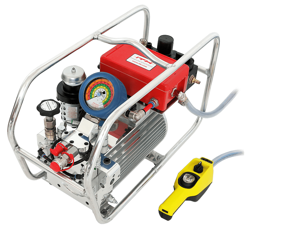
The HTL Hydraulic Torque Pump is a lightweight and portable solution which has been designed to be user-friendly ensuring ease of use for the operator whilst offering maximum efficiency.
With a maximum operating pressure of 10,000 psi / 700 bar and a precision pressure regulating valve HTLs range of torque pumps can be used with most leading brands of hydraulic torque tools.
Incorporating a compact solenoid valve system, protective frame and precision calibrated pressure gauge the HTL Hydraulic Torque Pump can be supplied with a multi-tool manifold allowing up to four tools to be used simultaneously ensuring equal parallel closure of flanges and joints, alternatively the pump can be supplied with a single tool manifold.
User Friendly and Portable Each pump is user friendly and portable, incorporating an ergonomically designed carrying frame and four quick connect ports to enable up to 4 torque wrenches to be operated simultaneously, even in the harshest environments.

High performance two-stage pump provides higher cross-over pressure for faster cycle times and tool operation; 46 cubic inches / minute @ 10,000 psi (753,8 cm3 / minute @ 700 bar).

Simplex torque wrench pumps are available in both electric and air power. Simplex electric hydraulic pumps are smooth running, continuous duty pumps with permanent magnet motors that will start and run under full load on as little as 60VAC. An integrated auto shut-off switch, along with a steel reservoir, keeps the oil and pump cool and helps prevent pump breakdown.

The many types of hydraulic pumps available today mean there’s one to suit just about any hydraulic application imaginable. But with so many features to consider, for anyone choosing a pump for the first time the choices may seem overwhelming.
Before you can select the right pump, first of all, you should understand the basics, and also the features that can be configured. Answering a few key questions about your intended applications will help you narrow the options.
A key consideration is how you want the pump to be powered. What drives this decision is the location where you will be carrying out the work. For example, if you are working in a hazardous environment, a ‘spark free’ (ATEX certified) air-driven hydraulic pump will offer a safer solution.
If working at a remote location without access to compressed air or electric power, a battery-powered pump is the way to go. Manually powered pumps, such as foot pumps and hand pumps, offer a simple solution for smaller jobs. Especially those where the operation doesn’t need to be repeated many times or when a very slow level of force is needed in a testing environment.
Most hydraulic pump manufacturers categorize their pumps by the intended pairing to the hydraulic tool and application. It’s worth noting there are key differences that make them suited to each hydraulic application.
Do you plan to use a pump with a hydraulic cylinder? The major consideration is whether you need a pump designed for a single or double-acting application. If the cylinder is double-acting, the pump will need at least two ports. One for the advance line – to extend the cylinder, the other for the return line – to retract it.
Pumps for hydraulic torque wrenches include a user-adjustable relief valve that allows the operator to easily set the correct torque pressure. They usually also include an onboard pressure gauge which can be either analog or digital.
By nature, pumps are generally very heavy, but lighter models are available which are easier to lift and carry to the work location. Roll cages are also a good feature to provide extra durability.
Hydraulic tensioner pumps are available in manual, air, and electric powered configurations. What makes a tensioner pump different is the capacity to work at very high pressures up to 21,750 psi (1500 bar). Pro Tip: Because these pumps operate at very high pressures you must always use fittings and hoses designed for these pressures.
Machinery used in manufacturing plants often include built-in hydraulics to operate workholding setups. However, where there isn’t such a system, (or if the hydraulic pressure needs increasing), a separate pump can be added.
These types of fixed bench application types of hydraulic pumps are powered by compressed air or electricity. Air-operated hydraulic pumps are powered by workshop air and are best suited to low or medium-duty cycles. Electric powered pumps are recommended for high-duty cycle applications and automation. They offer great versatility, low noise and provide the highest level of performance and durability.
For multi-point lifts, a controlled lifting pump offers a better solution than independently operated pumps. High precision movement of large objects requires synchronization of multiple lifting points. This can be achieved using a controlled lifting pump. By regulating the oil flow to each cylinder, these pumps provide incredibly accurate positional control. Manual intervention is minimized, the structural integrity of the load is maintained, and productivity and safety is assured.
Controlled lifting pumps feature both single and synchronized multiple outlet control either through joystick or pendant operation. More sophisticated models such as the EVO Synchronous Lifting System use stroke sensors. These can provide accuracy of up to 0.040 in (1 mm) between leading and lagging cylinders.
Technical and performance considerations can be examined in great detail and will be covered in a pump series of blog posts. But for overview purposes consider the following checklist to match your intended use.
For specifications of all types of hydraulic pumps visit the Enerpac website. If you need guidance get in touch with your nearest Enerpac distributor.

Hand Torque ToolsHand Torque Tools Our range of hand torque tools covers a wide selection of high-quality torque wrenches, torque screwdrivers and manual torque multipliers. The manufacturers we represent have decades of experience in torque tools and their models are trusted worldwide by both assembly industry professionals and hobbyist using torque tools. Our selection includes torque wrenches with click-type, break-back, electronic, slipping-type and dial-measuring mechanisms. The wrenches and screwdrivers can be divided into two basic types: scale and pre-set. Scale torque wrenches and screwdrivers can be adjusted to different torque values and their model-specific torque range is based on the requirements of EN ISO 6789: 2017. In pre-set models, the torque value of the torque tool is calibrated and set to a specified value that is not intended to be changed by the user during operation. In our versatile series of torque multipliers, you will find the right solutions for applications where extremely high torque values must be reached by hand. Torque multipliers are a great choice for example for less frequent maintenance needs where, for example cost reasons, switching to hydraulic, pneumatic or electronic methods has not been yet desired. In addition, torque multipliers allow reaching significantly higher torque values than…

The hydraulic torque wrenches type CX fit into radially limited spaces. For applications with varying reaction points the reaction arm can be easily adjusted, no extra parts or tools required. The dual-hose and TWIN-swivel connection offers various options to position the hydraulic hoses and fast operation with the ITH hydraulic pumps type DAX.
The high degree of adjustment possible with the reaction arm allows for positioning to get the best leverage on each bolt. The fine-tooth socket of the patented ratchet system guarantees a steady transfer of torque. The TWIN-swivel connection and dual-hose system offers a high amount of flexibility in tight places. The TWIN-swivel connection offers various options to position the hydraulic hoses. The component design (hydraulic cylinder, ratchet system, housing, and reaction arm) allows for quick replacement of worn parts.
Hydraulic motors are rotary or mechanical actuators that operate by converting hydraulic pressure or fluid energy into torque and angular displacement.
Motor displacement is the volume of fluid required to turn on the motor’s motor output shaft through one revolution. Cubic inches and cubic centimeters per revolution are the common units that are used for motor displacement. Depending on the type of motor used and application, the displacement may be a fixed or variable quantity. In a fixed displacement motor the torque is constant. The speed of the motor can be varied when controlling the amount of input flow that gets into the motor. Variable torque and speed can be obtained if the motor used is a variable displacement motor.
The torque output of a motor can be expressed either in foot-pounds or inch-pounds. It’s a function of the pressure in a system and the motor displacement. The specific pressure drops in a motor can be evaluated based on motor torque ratings given by the manufacturer.
Starting torque is the ability of a hydraulic motor to make a load start moving. The starting torque indicates the amount of torque that a hydraulic motor can develop to make a load start turning. It can be expressed as a fraction or percentage of the theoretical torque. The starting torque for piston, vane, and common gear motors is usually between 70% to 80% of the theoretical value.
Braking torque is the torque required to make a stationary load start rotating or turning. It requires more torque to make a load start moving than to keep the load moving.
Running torque is the torque associated with either the motor or the motor’s load. When referring to the load, it shows the torque that keeps rotating. When referring to a motor it shows the actual torque a motor creates to keep the load turning. For common vane, piston, and gear motors, the running torque is approximately 90% of the theoretical value.
Mechanical efficiency measures the effectiveness found in a machine or a mechanical system. This can be obtained from different variables and in hydraulic motors, torque usually is used. In hydraulic motors, mechanical efficiency refers to the ratio of the actual torque to be delivered to the theoretical torque.
Hydraulic motors work by converting hydraulic pressure or fluid energy into torque and angular displacement. Some components operate inside these motors to develop the required. Below is a list of the key components that are used in most hydraulic motors and their corresponding functions
In hydraulic motors, the rotor is the part that rotates after being triggered by a mechanism inside the motor. These mechanisms differ depending on the type of motor, for example in a gear-type hydraulic motor, the rotor starts rotating after meshing of the gears and fluid flow. In a vane type hydraulic motor, the rotor is triggered by the pressing of the vanes.
A driveshaft (also known as a propeller) is part of a hydraulic motor that is responsible for delivering or transferring the torque created inside the motor to the outside environment where it can be used for lifting loads and other applications. Most driveshafts are made of metals and have gear teeth on their ends.
Hydraulic motors operate by manipulation of the flow of fluid inside the motor. Directional control valves are designed to control fluid flow inside the motor. In most hydraulic and pneumatic systems these valves allow the fluids such as oil, water, air to flow from into different parts according to the control patterns and mechanisms of the system.
Hydraulic motors have a casing that protects and contains the components. They are made of different materials such as stainless steel, titanium, cast iron, low carbon steel, nickel, etc. Cases come in various shapes according to the arrangements of the components inside the motor.
A piston rod is a bar that is machined precisely and used to transmit a force created in a hydraulic or pneumatic system to a machine’s component performing the work. In hydraulic motors, piston rods are mainly used in piston-type motors to produce a turning movement.
Hydraulic motors use fluids to transmit energy from one point to another. Most hydraulic motors use water-based, petroleum-based, and synthetic fluids. The widely used is petroleum-based which is also known as mineral-based. This mineral-based product comes in many forms depending on the additives used and the quality of the crude oil used. Common fluid additives include anti-corrosion agents, demulsifiers, extreme pressure agents, rust, oxidation inhibitors, and defoamants.
Bearings are mechanical components that enable the rotation of parts by reducing friction and holding the load. In hydraulic motors the bearing is mainly used on the driveshaft to enable smooth and efficient rotation of the shaft. Many types of bearings are used on rotating shafts and the choice of one depends on many factors such as shaft speed, amount of load, the direction of the load, type of fluid used, etc.
It is important to know and understand how hydraulic pumps and motors differ from each other. Hydraulic pumps and motors operate similarly to each other to such an extent that some people do not know the differences. Some use the word pump when in effect they are talking about a motor and vice versa.
Hydraulic motors can operate in either direction. Hydraulic motors have mechanisms that allow them to rotate in either direction (negative or positive rotation) are required to have positive and negative rotation, which is why their internal structure is symmetrical, and hydraulic pumps generally rotate in a single direction, so that requirement is not necessary.
For example, in a vane motor, the blades can only be arranged in a radial manner. It can not be inclined like a vane pump, because this will cause the blades to be broken when reversing. The distribution plate in the axial plunger motor is supposed to have a symmetrical design, in that case, the axial plunger of the pump is not; the gear motor should have a separate leakage tube.
Hydraulic pumps are mainly used when they are connected with a prime mover and motors are connected with loads. The pump in essence has no radial loads such as pulleys, sprockets, belts which can be found in hydraulic motors.
Low-speed high torque (LSHT) motors are sometimes called high torque low RPM (revs per minute) motors and are designed to cater to heavy loads and equipment moving at a slower speed. These motors are characterized by speeds ranging from 0.1rpm to about 1000rpm. They provide high torque or power which operates at a slower speed. Some of the applications of LSHT motors include moving of gates, doors, lifts, etc. LSHT motors are used in environments and systems where the machinery is supposed to lift considerable weight in an environment that is smooth, controlled, and safe.
High-speed low torque (HSLT) hydraulic motors are sometimes referred to as high revs per minute (RPM) motors are designed to operate at high speeds ranging from 1 000 rpm to 14 000 rpm. They are used when the load is light because they have a low torque range. They can be used for applications in the utility, earthmoving, forestry, material handling etc.
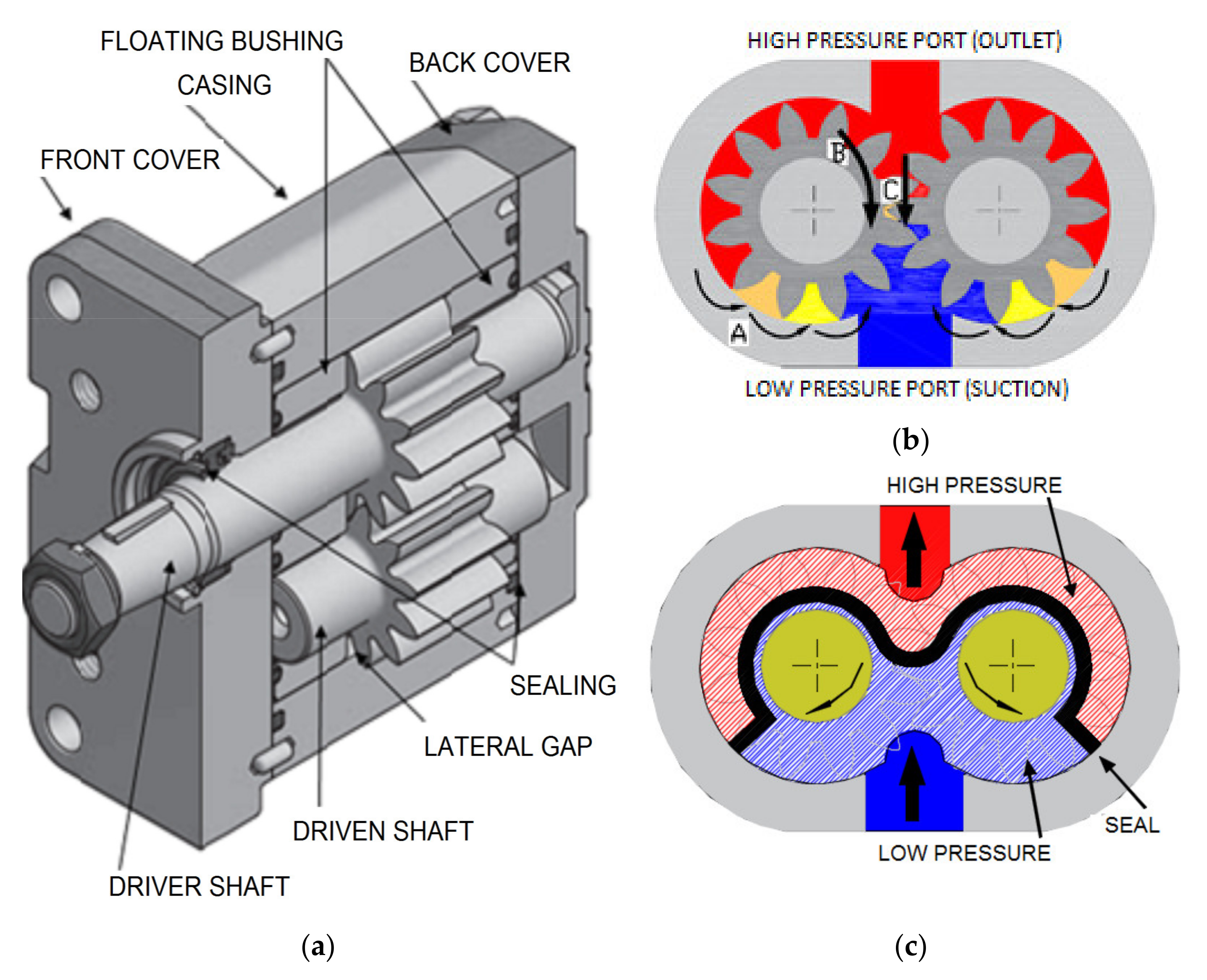
In this gear type, the hydraulic motor is made of two gears which are called the driven gear and the idle gear. The driven gear is connected to the output shaft usually by means of a key. Inside the motor is high pressure oil which flows into the sides around the gear tips and flows into the motor housing exiting through the outlet port. In the process, the gears mesh, and this will not allow oil coming from the outlet to flow back into the inlet side.
A small amount of this oil is used for lubrication of the gears. This oil is bled through the bearings (hydrodynamic), and the oil enters through the pressure side of the gears. The spur gears are popularly used in these types of hydraulic motors. If the gears are not manufactured to standards, they may become subject to vibration and may be noisy during the operation of the motor.
Internal gear motors have similar features and characteristics to external gear motors. The smooth operation of the gears characterizes the motors as compared to external gears where they are subjected to vibration causing noisy situations. They have one external gear that is used to mesh with the circumference of a larger gear. Internal gears are found in two versions namely the gerotor motor (mainly used in mobile systems and hydraulic technologies) and the gerotor motor.
In these gear motors a crescent vane is used to separate the discharge volume from the inlet volume between the two gears. When the hydraulic fluid enters through the inlet volume it causes the pressure to increase causing the volume to expand and this results in the gears rotating. The fluid will be forced out as the gears continue to rotate.
Hydraulic motors operate by creating an imbalance due to pressure which results in the rotation of the shaft. In vane motors, this imbalance is a result of the difference when the vane area is exposed to hydraulic pressure. Vane motors have a hydraulic balance which prevents the rotor from sideloading the shaft. The pressure difference develops the torque as the oil from the pump is forced to go through the motor.
Vane motors are usually made of a cartridge configuration of a motor housing. Their design is like that of a vane pump. They are characterized by two-port plates that separate the outlet and inlet ports as they put in between them the cam and rotor ring. Inside the cylindrical case of a vane motor is a ring mounted. This ring is made up of radial slots where there are sliding vanes. The vanes operate by pressing inside, against the wall of the cylindrical case. The ring rotates when the vanes are spring forced against the wall due to centrifugal force.
The radial-piston type hydraulic motor operates by transforming the energy created by the fluid pressure into mechanical energy (rotation). There is a directional valve, which is a fixed and central part of the configuration, it has two lines for fluid flow where one is for draining and another for fluid intake. The rotor is for turning in the directional valve which is fitted with radial bores. This will cause the free-floating pistons to operate.
The pistons which are in contact with the track that is fixed and rotated by the rotor produce a reciprocating motion with respect to the rotor. To keep the motor’s torque at a constant rate, they usually install an odd number of cylinders.
When the hydraulic fluid, that is pressurized by the pump, gets into the bores it presses the pistons against the stator usually for half a revolution. In the following half revolution, the fluid is delivered into the draining line connected to the directional valve. If the motor is operating under pressure loading on the motor piston, the stator will exert stress on the piston, and this will make the pistons and the rotor rotate. When this happens the output shaft of the motor is driven. Most of these systems are fitted with rollers which reduce the losses caused by piston friction on the track.
Axial piston-type hydraulic motors are also known as barrel motors. In these motors the plate of the drive shaft is positioned at an angle with respect to the barrel of the motor, the intake of fluid in the cylinders results in the movement of the pistons, causing the drive to rotate. In each cylinder, there is 1 phase of output and of intake per rotation. The piston operates when it is applied to the inclined plate with a force proportional to the pressure. This force reduces the angle and creates a force that makes the plate rotate.
When choosing a hydraulic motor to use there are factors that one needs to consider when designing an efficient system. The motor used should match the system requirement and if it does not this might affect the whole system. Below is a list of some of the factors and questions to consider.
There are many applications that hydraulic motors can be used for. These motors are made of different materials meaning they respond differently to operating conditions. Some are strong enough to withstand vibrations and harsh conditions and these are mainly used for industrial applications.
Knowing the expected life of a motor and the bearing to be used can help to plan with regard to application and maintenance. There are some complicated machines where it does not make sense to fit a motor type that has a short life span. There are many bearings that can be used for the rotor and shaft. These will depend on the forces and torque produced because bearings are used according to the force that acts on their surface area.
Before one can choose a type of motor to use, they need to gather installation information as well. This is because other motor types require a lot of expertise and are complicated to install. It is essential to talk with professionals about the other costs that are involved before purchasing a hydraulic motor.
A closed-loop in a hydraulic system is also known as a hydrostatic drive and is commonly found in mobile systems and industrial machines such as conveyors. In a closed-loop, the fluid flows directly from the pump to the motor and then returns to the pump without entering a reservoir. The fluid flow determined the speed of the motor. In an open loop, the fluid flows from the motor to the pump through a reservoir. Before choosing the right motor for the system it is essential to understand the loop that will operate in the specific hydraulic system.
Hydraulic motors play a vital role in the engineering and automation of many systems in our everyday lives. Although some of them are complex, most of these motors use simple operating principles which are easy to understand and are user-friendly.
Hydraulic pumps are mechanisms in hydraulic systems that move hydraulic fluid from point to point initiating the production of hydraulic power. Hydraulic pumps are sometimes incorrectly referred to as “hydrolic” pumps.
They are an important device overall in the hydraulics field, a special kind of power transmission which controls the energy which moving fluids transmit while under pressure and change into mechanical energy. Other kinds of pumps utilized to transmit hydraulic fluids could also be referred to as hydraulic pumps. There is a wide range of contexts in which hydraulic systems are applied, hence they are very important in many commercial, industrial, and consumer utilities.
“Power transmission” alludes to the complete procedure of technologically changing energy into a beneficial form for practical applications. Mechanical power, electrical power, and fluid power are the three major branches that make up the power transmission field. Fluid power covers the usage of moving gas and moving fluids for the transmission of power. Hydraulics are then considered as a sub category of fluid power that focuses on fluid use in opposition to gas use. The other fluid power field is known as pneumatics and it’s focused on the storage and release of energy with compressed gas.
"Pascal"s Law" applies to confined liquids. Thus, in order for liquids to act hydraulically, they must be contained within a system. A hydraulic power pack or hydraulic power unit is a confined mechanical system that utilizes liquid hydraulically. Despite the fact that specific operating systems vary, all hydraulic power units share the same basic components. A reservoir, valves, a piping/tubing system, a pump, and actuators are examples of these components. Similarly, despite their versatility and adaptability, these mechanisms work together in related operating processes at the heart of all hydraulic power packs.
The hydraulic reservoir"s function is to hold a volume of liquid, transfer heat from the system, permit solid pollutants to settle, and aid in releasing moisture and air from the liquid.
Mechanical energy is changed to hydraulic energy by the hydraulic pump. This is accomplished through the movement of liquid, which serves as the transmission medium. All hydraulic pumps operate on the same basic principle of dispensing fluid volume against a resistive load or pressure.
Hydraulic valves are utilized to start, stop, and direct liquid flow in a system. Hydraulic valves are made of spools or poppets and can be actuated hydraulically, pneumatically, manually, electrically, or mechanically.
The end result of Pascal"s law is hydraulic actuators. This is the point at which hydraulic energy is transformed back to mechanical energy. This can be accomplished by using a hydraulic cylinder to transform hydraulic energy into linear movement and work or a hydraulic motor to transform hydraulic energy into rotational motion and work. Hydraulic motors and hydraulic cylinders, like hydraulic pumps, have various subtypes, each meant for specific design use.
The essence of hydraulics can be found in a fundamental physical fact: fluids are incompressible. (As a result, fluids more closely resemble solids than compressible gasses) The incompressible essence of fluid allows it to transfer force and speed very efficiently. This fact is summed up by a variant of "Pascal"s Principle," which states that virtually all pressure enforced on any part of a fluid is transferred to every other part of the fluid. This scientific principle states, in other words, that pressure applied to a fluid transmits equally in all directions.
Furthermore, the force transferred through a fluid has the ability to multiply as it moves. In a slightly more abstract sense, because fluids are incompressible, pressurized fluids should keep a consistent pressure just as they move. Pressure is defined mathematically as a force acting per particular area unit (P = F/A). A simplified version of this equation shows that force is the product of area and pressure (F = P x A). Thus, by varying the size or area of various parts inside a hydraulic system, the force acting inside the pump can be adjusted accordingly (to either greater or lesser). The need for pressure to remain constant is what causes force and area to mirror each other (on the basis of either shrinking or growing). A hydraulic system with a piston five times larger than a second piston can demonstrate this force-area relationship. When a force (e.g., 50lbs) is exerted on the smaller piston, it is multiplied by five (e.g., 250 lbs) and transmitted to the larger piston via the hydraulic system.
Hydraulics is built on fluids’ chemical properties and the physical relationship between pressure, area, and force. Overall, hydraulic applications allow human operators to generate and exert immense mechanical force with little to no physical effort. Within hydraulic systems, both oil and water are used to transmit power. The use of oil, on the other hand, is far more common, owing in part to its extremely incompressible nature.
Pressure relief valves prevent excess pressure by regulating the actuators’ output and redirecting liquid back to the reservoir when necessary. Directional control valves are used to change the size and direction of hydraulic fluid flow.
While hydraulic power transmission is remarkably useful in a wide range of professional applications, relying solely on one type of power transmission is generally unwise. On the contrary, the most efficient strategy is to combine a wide range of power transmissions (pneumatic, hydraulic, mechanical, and electrical). As a result, hydraulic systems must be carefully embedded into an overall power transmission strategy for the specific commercial application. It is necessary to invest in locating trustworthy and skilled hydraulic manufacturers/suppliers who can aid in the development and implementation of an overall hydraulic strategy.
The intended use of a hydraulic pump must be considered when selecting a specific type. This is significant because some pumps may only perform one function, whereas others allow for greater flexibility.
The pump"s material composition must also be considered in the application context. The cylinders, pistons, and gears are frequently made of long-lasting materials like aluminum, stainless steel, or steel that can withstand the continuous wear of repeated pumping. The materials must be able to withstand not only the process but also the hydraulic fluids. Composite fluids frequently contain oils, polyalkylene glycols, esters, butanol, and corrosion inhibitors (though water is used in some instances). The operating temperature, flash point, and viscosity of these fluids differ.
In addition to material, manufacturers must compare hydraulic pump operating specifications to make sure that intended utilization does not exceed pump abilities. The many variables in hydraulic pump functionality include maximum operating pressure, continuous operating pressure, horsepower, operating speed, power source, pump weight, and maximum fluid flow. Standard measurements like length, rod extension, and diameter should be compared as well. Because hydraulic pumps are used in lifts, cranes, motors, and other heavy machinery, they must meet strict operating specifications.
It is critical to recall that the overall power generated by any hydraulic drive system is influenced by various inefficiencies that must be considered in order to get the most out of the system. The presence of air bubbles within a hydraulic drive, for example, is known for changing the direction of the energy flow inside the system (since energy is wasted on the way to the actuators on bubble compression). Using a hydraulic drive system requires identifying shortfalls and selecting the best parts to mitigate their effects. A hydraulic pump is the "generator" side of a hydraulic system that initiates the hydraulic procedure (as opposed to the "actuator" side that completes the hydraulic procedure). Regardless of disparities, all hydraulic pumps are responsible for displacing liquid volume and transporting it to the actuator(s) from the reservoir via the tubing system. Some form of internal combustion system typically powers pumps.
While the operation of hydraulic pumps is normally the same, these mechanisms can be split into basic categories. There are two types of hydraulic pumps to consider: gear pumps and piston pumps. Radial and axial piston pumps are types of piston pumps. Axial pumps produce linear motion, whereas radial pumps can produce rotary motion. The gear pump category is further subdivided into external gear pumps and internal gear pumps.
Each type of hydraulic pump, regardless of piston or gear, is either double-action or single-action. Single-action pumps can only pull, push, or lift in one direction, while double-action pumps can pull, push, or lift in multiple directions.
Vane pumps are positive displacement pumps that maintain a constant flow rate under varying pressures. It is a pump that self-primes. It is referred to as a "vane pump" because the effect of the vane pressurizes the liquid.
This pump has a variable number of vanes mounted onto a rotor that rotates within the cavity. These vanes may be variable in length and tensioned to maintain contact with the wall while the pump draws power. The pump also features a pressure relief valve, which prevents pressure rise inside the pump from damaging it.
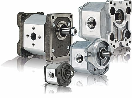
Internal gear pumps and external gear pumps are the two main types of hydraulic gear pumps. Pumps with external gears have two spur gears, the spurs of which are all externally arranged. Internal gear pumps also feature two spur gears, and the spurs of both gears are internally arranged, with one gear spinning around inside the other.
Both types of gear pumps deliver a consistent amount of liquid with each spinning of the gears. Hydraulic gear pumps are popular due to their versatility, effectiveness, and fairly simple design. Furthermore, because they are obtainable in a variety of configurations, they can be used in a wide range of consumer, industrial, and commercial product contexts.
Hydraulic ram pumps are cyclic machines that use water power, also referred to as hydropower, to transport water to a higher level than its original source. This hydraulic pump type is powered solely by the momentum of moving or falling water.
Ram pumps are a common type of hydraulic pump, especially among other types of hydraulic water pumps. Hydraulic ram pumps are utilized to move the water in the waste management, agricultural, sewage, plumbing, manufacturing, and engineering industries, though only about ten percent of the water utilized to run the pump gets to the planned end point.
Despite this disadvantage, using hydropower instead of an external energy source to power this kind of pump makes it a prominent choice in developing countries where the availability of the fuel and electricity required to energize motorized pumps is limited. The use of hydropower also reduces energy consumption for industrial factories and plants significantly. Having only two moving parts is another advantage of the hydraulic ram, making installation fairly simple in areas with free falling or flowing water. The water amount and the rate at which it falls have an important effect on the pump"s success. It is critical to keep this in mind when choosing a location for a pump and a water source. Length, size, diameter, minimum and maximum flow rates, and speed of operation are all important factors to consider.
Hydraulic water pumps are machines that move water from one location to another. Because water pumps are used in so many different applications, there are numerous hydraulic water pump variations.
Water pumps are useful in a variety of situations. Hydraulic pumps can be used to direct water where it is needed in industry, where water is often an ingredient in an industrial process or product. Water pumps are essential in supplying water to people in homes, particularly in rural residences that are not linked to a large sewage circuit. Water pumps are required in commercial settings to transport water to the upper floors of high rise buildings. Hydraulic water pumps in all of these situations could be powered by fuel, electricity, or even by hand, as is the situation with hydraulic hand pumps.
Water pumps in developed economies are typically automated and powered by electricity. Alternative pumping tools are frequently used in developing economies where dependable and cost effective sources of electricity and fuel are scarce. Hydraulic ram pumps, for example, can deliver water to remote locations without the use of electricity or fuel. These pumps rely solely on a moving stream of water’s force and a properly configured number of valves, tubes, and compression chambers.
Electric hydraulic pumps are hydraulic liquid transmission machines that use electricity to operate. They are frequently used to transfer hydraulic liquid from a reservoir to an actuator, like a hydraulic cylinder. These actuation mechanisms are an essential component of a wide range of hydraulic machinery.
There are several different types of hydraulic pumps, but the defining feature of each type is the use of pressurized fluids to accomplish a job. The natural characteristics of water, for example, are harnessed in the particular instance of hydraulic water pumps to transport water from one location to another. Hydraulic gear pumps and hydraulic piston pumps work in the same way to help actuate the motion of a piston in a mechanical system.
Despite the fact that there are numerous varieties of each of these pump mechanisms, all of them are powered by electricity. In such instances, an electric current flows through the motor, which turns impellers or other devices inside the pump system to create pressure differences; these differential pressure levels enable fluids to flow through the pump. Pump systems of this type can be utilized to direct hydraulic liquid to industrial machines such as commercial equipment like elevators or excavators.
Hydraulic hand pumps are fluid transmission machines that utilize the mechanical force generated by a manually operated actuator. A manually operated actuator could be a lever, a toggle, a handle, or any of a variety of other parts. Hydraulic hand pumps are utilized for hydraulic fluid distribution, water pumping, and various other applications.
Hydraulic hand pumps may be utilized for a variety of tasks, including hydraulic liquid direction to circuits in helicopters and other aircraft, instrument calibration, and piston actuation in hydraulic cylinders. Hydraulic hand pumps of this type use manual power to put hydraulic fluids under pressure. They can be utilized to test the pressure in a variety of devices such as hoses, pipes, valves, sprinklers, and heat exchangers systems. Hand pumps are extraordinarily simple to use.
Each hydraulic hand pump has a lever or other actuation handle linked to the pump that, when pulled and pushed, causes the hydraulic liquid in the pump"s system to be depressurized or pressurized. This action, in the instance of a hydraulic machine, provides power to the devices to which the pump is attached. The actuation of a water pump causes the liquid to be pulled from its source and transferred to another location. Hydraulic hand pumps will remain relevant as long as hydraulics are used in the commerce industry, owing to their simplicity and easy usage.
12V hydraulic pumps are hydraulic power devices that operate on 12 volts DC supplied by a battery or motor. These are specially designed processes that, like all hydraulic pumps, are applied in commercial, industrial, and consumer places to convert kinetic energy into beneficial mechanical energy through pressurized viscous liquids. This converted energy is put to use in a variety of industries.
Hydraulic pumps are commonly used to pull, push, and lift heavy loads in motorized and vehicle machines. Hydraulic water pumps may also be powered by 12V batteries and are used to move water out of or into the desired location. These electric hydraulic pumps are common since they run on small batteries, allowing for ease of portability. Such portability is sometimes required in waste removal systems and vehiclies. In addition to portable and compact models, options include variable amp hour productions, rechargeable battery pumps, and variable weights.
While non rechargeable alkaline 12V hydraulic pumps are used, rechargeable ones are much more common because they enable a continuous flow. More considerations include minimum discharge flow, maximum discharge pressure, discharge size, and inlet size. As 12V batteries are able to pump up to 150 feet from the ground, it is imperative to choose the right pump for a given use.
Air hydraulic pumps are hydraulic power devices that use compressed air to stimulate a pump mechanism, generating useful energy from a pressurized liquid. These devices are also known as pneumatic hydraulic pumps and are applied in a variety of industries to assist in the lifting of heavy loads and transportation of materials with minimal initial force.
Air pumps, like all hydraulic pumps, begin with the same components. The hydraulic liquids, which are typically oil or water-based composites, require the use of a reservoir. The fluid is moved from the storage tank to the hydraulic cylinder via hoses or tubes connected to this reservoir. The hydraulic cylinder houses a piston system and two valves. A hydraulic fluid intake valve allows hydraulic liquid to enter and then traps it by closing. The discharge valve is the point at which the high pressure fluid stream is released. Air hydraulic pumps have a linked air cylinder in addition to the hydraulic cylinder enclosing one end of the piston.
The protruding end of the piston is acted upon by a compressed air compressor or air in the cylinder. When the air cylinder is empty, a spring system in the hydraulic cylinder pushes the piston out. This makes a vacuum, which sucks fluid from the reservoir into the hydraulic cylinder. When the air compressor is under pressure, it engages the piston and pushes it deeper into the hydraulic cylinder and compresses the liquids. This pumping action is repeated until the hydraulic cylinder pressure is high enough to forcibly push fluid out through the discharge check valve. In some instances, this is connected to a nozzle and hoses, with the important part being the pressurized stream. Other uses apply the energy of this stream to pull, lift, and push heavy loads.
Hydraulic piston pumps transfer hydraulic liquids through a cylinder using plunger-like equipment to successfully raise the pressure for a machine, enabling it to pull, lift, and push heavy loads. This type of hydraulic pump is the power source for heavy-duty machines like excavators, backhoes, loaders, diggers, and cranes. Piston pumps are used in a variety of industries, including automotive, aeronautics, power generation, military, marine, and manufacturing, to mention a few.
Hydraulic piston pumps are common due to their capability to enhance energy usage productivity. A hydraulic hand pump energized by a hand or foot pedal can convert a force of 4.5 pounds into a load-moving force of 100 pounds. Electric hydraulic pumps can attain pressure reaching 4,000 PSI. Because capacities vary so much, the desired usage pump must be carefully considered. Several other factors must also be considered. Standard and custom configurations of operating speeds, task-specific power sources, pump weights, and maximum fluid flows are widely available. Measurements such as rod extension length, diameter, width, and height should also be considered, particularly when a hydraulic piston pump is to be installed in place of a current hydraulic piston pump.
Hydraulic clutch pumps are mechanisms that include a clutch assembly and a pump that enables the user to apply the necessary pressure to disengage or engage the clutch mechanism. Hydraulic clutches are crafted to either link two shafts and lock them together to rotate at the same speed or detach the shafts and allow them to rotate at different speeds as needed to decelerate or shift gears.
Hydraulic pumps change hydraulic energy to mechanical energy. Hydraulic pumps are particularly designed machines utilized in commercial, industrial, and residential areas to generate useful energy from different viscous liquids pressurization. Hydraulic pumps are exceptionally simple yet effective machines for moving fluids. "Hydraulic" is actually often misspelled as "Hydralic". Hydraulic pumps depend on the energy provided by hydraulic cylinders to power different machines and mechanisms.
There are several different types of hydraulic pumps, and all hydraulic pumps can be split into two primary categories. The first category includes hydraulic pumps that function without the assistance of auxiliary power sources such as electric motors and gas. These hydraulic pump types can use the kinetic energy of a fluid to transfer it from one location to another. These pumps are commonly called ram pumps. Hydraulic hand pumps are never regarded as ram pumps, despite the fact that their operating principles are similar.
The construction, excavation, automotive manufacturing, agriculture, manufacturing, and defense contracting industries are just a few examples of operations that apply hydraulics power in normal, daily procedures. Since hydraulics usage is so prevalent, hydraulic pumps are unsurprisingly used in a wide range of machines and industries. Pumps serve the same basic function in all contexts where hydraulic machinery is used: they transport hydraulic fluid from one location to another in order to generate hydraulic energy and pressure (together with the actuators).
Elevators, automotive brakes, automotive lifts, cranes, airplane flaps, shock absorbers, log splitters, motorboat steering systems, garage jacks and other products use hydraulic pumps. The most common application of hydraulic pumps in construction sites is in big hydraulic machines and different types of "off-highway" equipment such as excavators, dumpers, diggers, and so on. Hydraulic systems are used in other settings, such as offshore work areas and factories, to power heavy machinery, cut and bend material, move heavy equipment, and so on.
Fluid’s incompressible nature in hydraulic systems allows an operator to make and apply mechanical power in an effective and efficient way. Practically all force created in a hydraulic system is applied to the intended target.
Because of the relationship between area, pressure, and force (F = P x A), modifying the force of a hydraulic system is as simple as changing the size of its components.
Hydraulic systems can transfer energy on an equal level with many mechanical and electrical systems while being significantly simpler in general. A hydraulic system, for example, can easily generate linear motion. On the contrary, most electrical and mechanical power systems need an intermediate mechanical step to convert rotational motion to linear motion.
Hydraulic systems are typically smaller than their mechanical and electrical counterparts while producing equivalents amounts of power, providing the benefit of saving physical space.
Hydraulic systems can be used in a wide range of physical settings due to their basic design (a pump attached to actuators via some kind of piping system). Hydraulic systems could also be utilized in environments where electrical systems would be impractical (for example underwater).
By removing electrical safety hazards, using hydraulic systems instead of electrical power transmission improves relative safety (for example explosions, electric shock).
The amount of power that hydraulic pumps can generate is a significant, distinct advantage. In certain cases, a hydraulic pump could generate ten times the power of an electrical counterpart. Some hydraulic pumps (for example, piston pumps) cost more than the ordinary hydraulic component. These drawbacks, however, can be mitigated by the pump"s power and efficiency. Despite their relatively high cost, piston pumps are treasured for their strength and capability to transmit very viscous fluids.
Handling hydraulic liquids is messy, and repairing leaks in a hydraulic pump can be difficult. Hydraulic liquid that leaks in hot areas may catch fire. Hydraulic lines that burst may cause serious injuries. Hydraulic liquids are corrosive as well, though some are less so than others. Hydraulic systems need frequent and intense maintenance. Parts with a high factor of precision are frequently required in systems. If the power is very high and the pipeline cannot handle the power transferred by the liquid, the high pressure received by the liquid may also cause work accidents.
Even though hydraulic systems are less complex than electrical or mechanical systems, they are still complex systems that should be handled with caution. Avoiding physical contact with hydraulic systems is an essential safety precaution when engaging with them. Even when a hydraulic machine is not in use, active liquid pressure within the system can be a hazard.
Inadequate pumps can cause mechanical failure in the place of work that can have serious and costly consequences. Although pump failure has historically been unpredictable, new diagnostic technology continues to improve on detecting methods that previously relied solely on vibration signals. Measuring discharge pressures enables manufacturers to forecast pump wear more accurately. Discharge sensors are simple to integrate into existing systems, increasing the hydraulic pump"s safety and versatility.
Hydraulic pumps are devices in hydraulic systems that move hydraulic fluid from point to point, initiating hydraulic power production. They are an important device overall in the hydraulics field, a special kind of power transmission that controls the energy which moving fluids transmit while under pressure and change into mechanical energy. Hydraulic pumps are divided into two categories namely gear pumps and piston pumps. Radial and axial piston pumps are types of piston pumps. Axial pumps produce linear motion, whereas radial pumps can produce rotary motion. The construction, excavation, automotive manufacturing, agriculture, manufacturing, and defense contracting industries are just a few examples of operations that apply hydraulics power in normal, daily procedures.

Despite recent advances in predictive maintenance technologies, the maintenance professional’s ability to determine the remaining bearing life of a pump or motor, with a high degree of accuracy, remains elusive.
Deteriorating efficiency on the other hand is easy to detect. Because it typically shows itself through increased cycle times. In other words, the machine slows down. When this occurs, quantification of the efficiency loss is not always necessary. Reason being, if the machine slows to the point where its cycle time in unacceptably slow, the pump or motor is changed out. End of story.
In certain situations however, it can be helpful, even necessary, to quantify the pump or motor’s actual efficiency and compare it to the component’s native efficiency. And for this, an understanding of hydraulic pump and motor efficiency ratings is essential.
There are three categories of efficiency used to describe hydraulic pumps (and motors). Volumetric efficiency, mechanical/hydraulic efficiency and overall efficiency.
Volumetric efficiency is determined by dividing the actual flow delivered by a pump at a given pressure by its theoretical flow. Theoretical flow is calculated by multiplying the pump’s displacement per revolution by its driven speed. So if the pump has a displacement of 100 cc/rev and is being driven at 1000 RPM its theoretical flow is 100 liters/minute.
Actual flow has to be measured using a flow meter. If when tested, the above pump had an actual flow of 90 liters/minute at 207 bar (3000 PSI), we can say the pump has a volumetric efficiency of 90% at 207 bar (90 / 100 x 100 = 90%).
It’s volumetric efficiency we use most in the field to determine the condition of a hydraulic pump – based on its increase in internal leakage through wear or damage. But without reference to theoretical flow, the actual flow measured by the flow meter would be meaningless.
A pump’s mechanical/hydraulic efficiency is determined by dividing the theoretical torque required to drive it by the actual torque required to drive it. A mechanical/hydraulic efficiency of 100% would mean if the pump was delivering flow at zero pressure, no force or torque would be required to drive it. Intuitively, we know this is not possible – due to mechanical and fluid friction.
Like theoretical flow, theoretical drive torque can be calculated. For the above pump, in SI units: 100 cc/rev x 207 bar / 20 x pi = 329 Newton meters. But like actual flow, actual drive torque must be measured and this requires the use of a dynamometer. Not something we can-or need-to do in the field. For the purposes of this example though, let’s assume the actual drive torque was 360 Nm. Mechanical/hydraulic efficiency would be 91% (329 / 360 x 100 = 91%).
Overall efficiency is simply the product of volumetric and mechanical/hydraulic efficiency. So continuing with the above example, the overall efficiency of the pump is 0.9 x 0.91 x 100 = 82%. Typical overall efficiencies for different types of hydraulic pumps are shown in the table below (source: Bosch Rexroth):
Overall efficiency is used to calculate the drive power required by a pump at a given flow and pressure. For example, using the overall efficiencies from the table above, let us calculate, in SI units, the required drive power for an external gear pump and a bent axis piston pump at a flow of 90 liters/minute at 207 bar:
As you’d expect, the more efficient pump requires less drive power for the same output flow and pressure. With a little more math, we can quickly calculate the heat load of each pump:
No surprise then, that a system with gear pumps and motors requires a bigger heat exchanger than an equivalent (all other things equal) system with piston pumps and motors. And to discover six other costly mistakes you want to be sure to avoid with your hydraulic equipment, get “Six Costly Mistakes Most Hydraulics Users Make… And How You Can Avoid Them!” available for FREE download here.

In significant industrial segments across the globe, there continues to be major investment in large-scale equipment that incorporates heavy-duty material movement and handling systems. In mining applications such as bucket wheel excavators and conveyors, to metal shredders in recycling operations, as well as winch systems and drilling equipment in offshore applications, powerful low-speed drives that can deliver high torque and reliably function in rugged demanding environments are in high demand.
There are several kinds of drive platforms that are suitable for this. However, a growing number of operations are finding that the hydraulic direct drive (HDD) provides the performance these systems require. HDD systems offer significant performance advantages for applications where a heavy mass needs to be moved under variable speeds using a system that can handle “shock loads” (sudden increases in the weight and mass of loads being moved), combined with the ability to deliver energy-efficient and reliable performance — often operating 24 hours a day, seven days a week.
The most common use of HDD systems is for industrial applications moving heavy masses on a continuous basis with low speed and high torque, and especially high starting torque for operations with frequent stops and starts. The materials being moved can be done at low speeds, typically in a range from zero to 200 rotations per minute (RPMs).
HDDs provide that performance because of their unique design — most specifically because they are “direct drives” that deliver the full energy of their operation to the shaft they are driving. An HDD is a closed system with a low-speed hydraulic motor at its heart. Able to sustain high torque even at minimum speed, the hydraulic motor is mounted directly on the drive shaft — there is no need for a gear reducer, belts, chains, or sprockets.
Power is supplied to the hydraulic motor by a separate drive unit, which can be positioned almost anywhere in relation to the installation. The drive unit contains at least one standard AC induction motor, which runs at a fixed speed and drives a variable-displacement axial piston pump. It is the variable flow of oil from the pump that determines the speed and direction of the drive.
The complete HDD system also includes the intelligent pump controller, hydraulic fluid supply, and connecting hoses and wiring. The power unit is connected to the hydraulic motor on the shaft via cabling and hosing; this lets system designers position the pump, electric motor, and controllers in an enclosure away from the operational axis. This allows for greater design flexibility and protects these components from harsh operating conditions.
HDD systems are being more widely used in heavy equipment applications; nevertheless, there are other drive systems in use to provide the same function. More traditional industrial drives are generally available in two platforms: a medium-or high-speed drive motor, which can be either hydromechanical or electromechanical, combined with a gear reducer to provide the low-speed, high-torque operation.
Hydromechanical drives (HMDs) have basic torque and speed that are similar to those of an HDD, but the drive is connected to the drive shaft of the system through a gear reducer. This configuration creates mechanical losses that reduce the output torque. Exactly how much torque is lost depends on the type of gear reducer used, the number of gear stages it has, and the factor by which it has been overdimensioned.
There are several inherent advantages that HDD systems offer compared to other systems. With a geared drive solution, the electric motor, gear reducer, and coupling are mechanically connected to the driven shaft, often requiring considerable space around the machine. A direct drive is much more compact. Equally important is that close to 97 percent of the full power of the HDD system is applied directly to turn the driven shaft. A geared drive solution will also generate high additional torque in case of sudden speed changes caused by heavy shock loads. Failure to compensate for these can lead to considerable costs from breakdowns and resulting downtime. A direct drive eliminates this risk.
In contrast, an HDD will provide the full torque at zero speed immediately upon start-up. This lets mining operators slowly advance the speed from one RPM through very tight increments so that the belt is not strained yet the material is transported efficiently.
The simple, rugged design of hydraulic motors also enables them to start, stop, and reverse repeatedly without taxing the interior cams and other motor elements. This enables an operator to design the motion sequences to fit the load or work requirements of the machine the HDD is driving, stopping and starting as many times as is needed. With an ACD or HMD that uses a gear reducer, to perform the same number of starts and stops, the gearbox would need to be overdimensioned to handle those conditions without quickly wearing out the drive — and overdimensioning a gearbox can be an expensive solution.
HDD systems also offer superior speed and directional control compared to gearbox-couple drive solutions. Since the variable flow of oil from the pump determines the speed and direction of the drive, speed and directional control are not compromised by the limitations of the electric motor. And due to the hydraulic motor’s low moment of inertia, the response is almost instantaneous.
Along with the shock load resistance inherent in the technology, HDD technology also provides overload protection to safeguard machines and ensure maximum uptime. HDDs provide an adjustable pressure-limiting function, which prevents maximum torque from being exceeded in overload conditions. Maximum torque is prevented from being exceeded by destroking the pump as necessary during lengthy acceleration cycles and in overload conditions.
There are a few ways heavy equipment end users can implement HDD systems in their operations. There are some hydraulic motor suppliers who can provide the motor that mounts on the drive shaft; it would then be up to the end user or a hydraulics system integrator to obtain the variable-speed drive, hydraulic pump, controller, and other drive components and program the system to start-up.
Some hydraulics suppliers offer complete solutions in turnkey packages. Some suppliers also provide expert recommendations, installation support and effective repair services. Partnering with an expert supplier helps ensure that the right set of drives is engineered and installed on each piece of heavy-duty equipment to deliver the full advantages of HDD technology for the full system life cycle.
This article was written by Brian Howell, Large Hydraulic Drives Sales and Operations Manager, Bosch Rexroth (Bethlehem, PA). For more information, visit here.

Corey is the Managing Director of the Mentored Engineer and owner of Rasmussen Designs. He received his BSME from Baylor University and holds a professional engineering license in North Carolina and Texas. He has been an engineer since 2002 with extensive experience in engineering design, fabrication and troubleshooting. He specializes in mobile equipment, hydraulic systems and machine design. He has two patents


 8613371530291