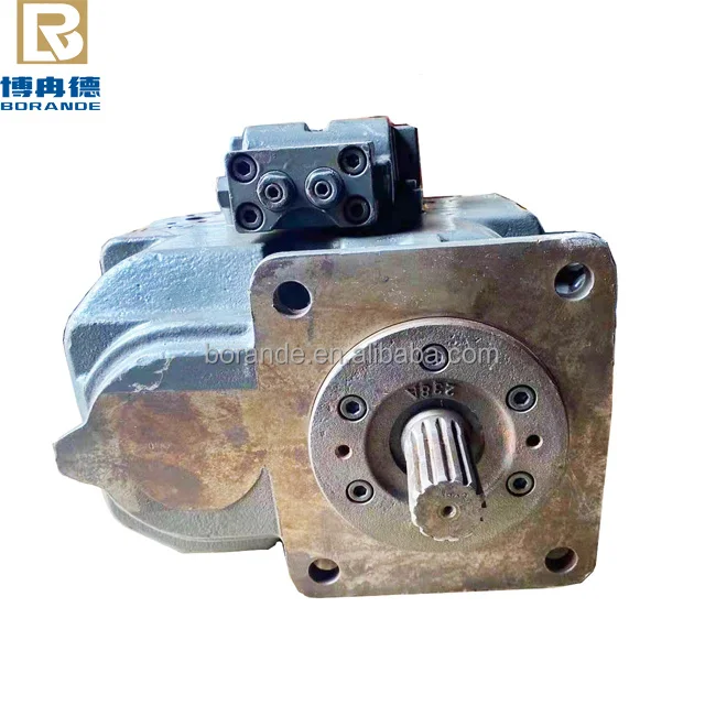
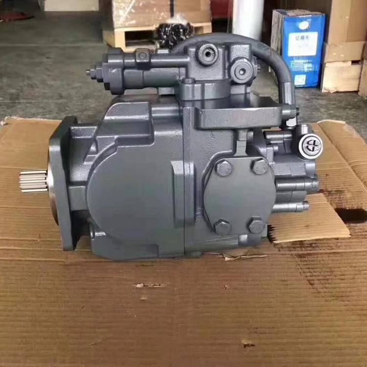
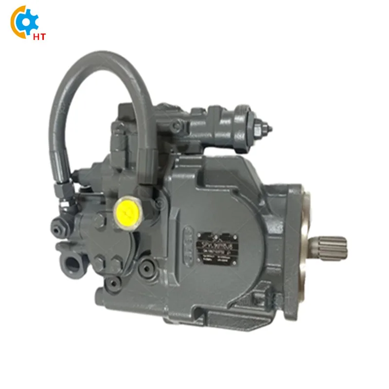
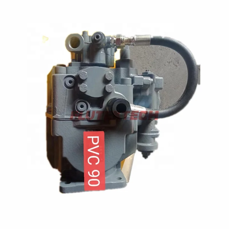
toshiba hydraulic pump free sample

1598 toshiba hydraulic pump products are offered for sale by suppliers on Alibaba.comAbout 11% % of these are construction machinery parts, 4%% are hydraulic pumps, and 2%% are other hydraulic parts.
A wide variety of toshiba hydraulic pump options are available to you, such as new, used.You can also choose from piston pump, gear pump and vane pump toshiba hydraulic pump,as well as from 1 year, 6 months, and 1.5 years toshiba hydraulic pump,And whether toshiba hydraulic pump is fittings, {2}, or {3}.

If you are supplying pump supplies, you can find the most favorable prices at Alibaba.com. Whether you will be working with piston type or diaphragm type systems, reciprocating or centrifugal, Alibaba.com has everything you need. You can also shop for different sizes hydraulic pump toshiba wholesale for your metering applications. If you operate a construction site, then you could need to find some concrete pump solutions that you can find at affordable rates at Alibaba.com. Visit the platform and browse through the collection of submersible and inline pump system, among other replaceable models.
A hydraulic pump toshiba comes in different makes and sizes, and you buy the tool depending on the application. The pump used by a filling station is not the one you use to fill up your tanks. There are high flow rate low pressure systems used to transfer fluids axially. On the other hand, you can go with radial ones dealing with a low flow rate and high-pressure fluid. The mixed flow pump variety combines radial and axial transfer mechanisms and works with medium flow and pressure fluids. Depending on what it will be pumping, you can then choose the hydraulic pump toshiba of choice from the collection at Alibaba.com.
Alibaba.com has been an excellent wholesale supplier of hydraulic pump toshiba for years. The supply consists of a vast number of brands to choose from, comes in different sizes, operations, and power sources. You can get a pump for residential and large commercial applications from the collection. Whether you want a water pump for your home, or run a repair and maintenance business, and need a supply of hyd pump to shiba, you can find the product you want from the vast collection at Alibcom.comther Whether it is for refrigeration, air conditioning, transfer, or a simple car wash business, anything you want, Alibaba.com has it.

In a global sense, the Hydraulic Pumps market is divided into segregated segments and dividers. Hydraulic Pumps The report provides the most up-to-date and specific information on crop production used in the Hydraulic Pumps field survey. All information points and data included in the Hydraulic Pumps market are digitally displayed in the form of bar graphs, pie charts, tables, and product numbers to provide a better understanding of users. The report represents the complete Hydraulic Pumps market situation in front of key people such as leaders, managers, industries, and managers. The author of the Hydraulic Pumpsmarket report has been very careful and has done extensive research on the Hydraulic Pumps market to compile all relevant and important information.
For Better Understanding, Download Free Sample PDF of Hydraulic Pumps Market Research Report @ https://marketresearch.biz/report/hydraulic-pumps-market/request-sample
The various sections on regional segmentation provide regional aspects of the global Hydraulic Pumps market. This section portrays the administrative construction that will doubtlessly affect the whole market. It highlights the political landscape in the market and predicts its influence on the Hydraulic Pumps market globally.
This report explains and provides detailed information about energy, cost structure, price, revenue share, sales, growth rate, company profile, imports, and technological advances, etc. It also defines the global size of the Hydraulic Pumps market in terms of production level, regions by region, average consumption, total limit, demand, and sales revenue.
Chapter 2- This section focuses on industry trends where market drivers are driven and high market patterns. It also provides developmental steps for key developers working within the Global Market Hydraulic Pumps. In addition, it provides the creation and limitation of testing when developing patterns of measurement, limit, creativity, and creative predictions of the Hydraulic Pumps Market
Chapter 3- This clip focuses on the types of items where the creation looks at the overall business size, cost, and overall business structure by the type of item being discussed, providing an in-depth global Hydraulic Pumps Market application.
Chapter 6- Organizational Profiles: Many players who drive the entire Hydraulic Pumps Market are printed during this section. The auditors provided data on their ongoing development within the Global Market Hydraulic Pumps, materials, income, creativity, business, and friends.
Chapter 7- The estimates of collection and construction estimates included in this section are in addition to the Hydraulic Pumps Market value in addition to key business categories.
Chapter 9- Worth Chain and Sales Analysis: An in-depth analysis of clients, retailers, deals channels, and key Market Series Hydraulic Pumps in general.

The present invention relates to a hydraulic control system for an injection molding machine, particularly to a hydraulic control system including a driving motor for a fixed delivery pump which is capable of supplying a hydraulic fluid at a rate corresponding to the driving speed of an hydraulic actuator included in the injection molding machine, and reducing a power consumption.
FIG. 4 shows a conventional hydraulic control system for an infection molding machine. A fixed delivery pump 1, which is driven by an induction motor 2, draws the hydraulic fluid from a reservoir 3 and delivers it through a proportional flow control valve 4 to actuators included in the injection molding machine. The actuators are ones such as a clamping cylinder 5, an injection cylinder 7 for driving a screw 6 to move forward and backward and a charging hydraulic motor 8 for driving the screw 6 for rotation. A solenoid valve 9 is operated to control the claimping cylinder 5 for a closing and opening operation for the mold. A solenoid valve 10 is operated to control the injection cylinder 7, which advances the screw 6 for an injection operation and to retract the screw 6 for a charging operation. A flow control valve 11 regulates a hydraulic fluid supplied to the charging hydraulic motor 8. A solenoid valve 12 is closed to suspend the supply of the hydraulic fluid to the hydraulic motor 8. The hydraulic pressure in the hydraulic system is determined by a pressure relief valve 13 as desired. The proportional flow control valve 4 controlls the flow of the hydraulic fluid on the basis of an electric signal S given thereto by a main controller 14 for the injection molding machine so as to supply the hydraulic fluid at a flow rate necessary for driving each of the actuators at a desired speed.
When clamping the mold in a clamping process, the proportional flow control valve 4 regulates the hydraulic fluid discharged from the fixed delivery pump 1 to flow through the solenoid valve 9 to the clamping cylinder 5 at a low flow rate which is predetermined by the controller 14. Initially, a movable platen, not shown, starts closing the mold at a low speed. Then, the proportional flow control valve 4 is controlled so as to supply the hydraulic fluid at a predetermined high flow rate to the mold clamping cylinder 5. In a final stage of the mold clamping operation, the hydraulic fluid is regulated to a predetermined low flow rate to close the mold gradually. After the mold has been fully closed, the hydraulic pressure in the clamping cylinder 5 is maintained to keep the mold clamped by a clamping force.
In a subsequent injection process, when the hydraulic fluid is supplied at a high flow rate to the injection cylinder 7, the screw 6 advances to inject a quantity of a molten polymer charged in front of the screw 6 into a cavity in the mold. After the injection process has been completed, a dwelling process is executed to prevent against a defect such as a sinkmark that occurs in a cooled polymer in the mold. In the dwelling process, the hydraulic pressure in the injection cylinder 7 is maintained until the polymer in the mold is cooled and solidified.
FIG. 5 shows another example of a conventional hydraulic control system for an injection molding machine. This hydraulic control system is provided with a large-capacity fixed delivery pump 17 and a small-capacity fixed delivery pump 18 with pressure relief valves 15 and 16, respectively, instead of the fixed delivery pump 1 as shown in FIG. 4. A solenoid valve 19 is controlled properly according to a desired flow rate. For example, when the clamping cylinder 5 is driven at a high speed, the solenoid valve 19 is opened so as to supply the hydraulic fluid with the clamping cylinder 5 from the both fixed delivery pump 17 and 18.
In the hydraulic control system shown in FIG. 4, the fixed delivery pump 1 is running so as to discharge continuously the hydraulic fluid at a maximum flow rate necessary to advance the screw 6. That leads to a power loss. For example, in the dwelling and cooling process in which a low flow rate should be supplied with the injection cylinder 7, surplus hydraulic fluid is returned through the pressure relief valve 13 into the reservoir 3. Thus, the fixed delivery pump 1, which is loaded continuously at the pressure set by the pressure relief valve 13, wastes a lot of power uselessly.
In the hydraulic control system shown in FIG. 5, a large flow of the hydraulic fluid is supplied with the clamping cylinder 5 through solenoid valve 19 by combining the delivery of pump 17 and 18. In a case that a small hydraulic flow should be delivered, the solenoid valve 19 is closed, and hydraulic fluid is delivered by the pump 18 with small capacity. However, the large capacity pump 17 is running continuously while the surplus hydraulic fluid is bent through the pressure relief valve 15. That is undesirable from the viewpoint of energy economy.
Accordingly, it is an object of the present invention to provide a hydraulic system for an injection molding machine, capable of operating at a low power consumption and of preventing wasting power, and including a pump driving motor for driving an oil pump to supply a hydraulic oil efficiently at a flow rate corresponding to the operating speed of a hydraulic actuator.
According to one aspect of the present invention, a hydraulic control system for an injection molding machine comprises a plurality of hydraulic actuators assigned respectively for driving functional units included in the injection molding machine; an hydraulic pump for supplying a hydraulic fluid to drive the hydraulic actuators; a pump driving motor for driving the hydraulic pump; a hydraulic circuit including solenoid valves for serving to direct the hydraulic fluid to the optional hydraulic actuators to drive the hydraulic actuators selectively; a controller that provides flow control signals for instructing flow rates corresponding to predetermined operating speeds at which the hydraulic actuators is driven according to respective stages of an injection molding cycle; a speed control valve, disposed in the hydraulic circuit at a position downstrean of the hydraulic pump, for controlling the flow rate of the hydraulic fluid to be supplied to the hydraulic actuators on the basis of the flow control signals; a motor controller using an inverter to control the pump driving motor for rotation at a desired rotational speed; and a pump speed setting means, connected between the controller and the motor controller, for determining rotational speeds of the hydraulic pump on the basis of the flow control signals provided by the controller.
The hydraulic control system of the present invention controls the pump driving motor for operation at operating speeds necessary for supplying the hydraulic fluid at flow rates respectively corresponding to the operating speeds of the hydraulic actuators, so that the hydraulic fluid can efficiently be supplied to the hydraulic actuators, the useless operation of the motor can be avoided to save power consumption.
The flow control signals to be given to the motor controller may include a motor stop signal to stop the pump driving motor, and the pump driving motor may be stopped while the hydraulic pump need not operate.
The operation of the pump driving motor may be controlled in a sequence control mode by the motor controller according to selected process of the injection molding cycle.
A hydraulic control system in a preferred embodiment according to the present invention will be described with reference to FIGS. 1 to 3, in which parts like or corresponding to those of the conventional hydraulic control systems previously described with reference to FIGS. 4 and 5 are designated by the same reference characters and the description thereof will be omitted. The hydraulic control system of the present invention differs from the conventional hydraulic systems in a pump driving motor and a control system thereof.
Referring to FIGS. 1 and 2A and 2B, a main controller 14 for controlling an injection molding machine gives an electric signal S which instructs a flow rate to a proportional flow control valve 4. The signal S is also fed into a signal converter 21. The signal converter 21 is connected between the main controller 14 and a inverter controller 22 provided with a transformer 24 for converting the electric signal S into a corresponding control voltage for controlling the inverter controller 22. The inverter controller 22 controls the rotational speed of a pump driving induction motor 23 which drives the fixed delivery pump 1. Accordingly, the rotational speed of the induction motor 23 is regulated according to the voltage of the electric signal S provided by the main controller 14 so that the induction motor 23 operates at an rotational speed corresponding to a predetermined flow rate at which the hydraulic fluid is to flow through the proportional flow control valve 4.
Since the induction motor 23 operates at an desired rotational speed corresponding to the required flow rate of the hydraulic fluid, the fixed delivery pump 1 delivers the necessary hydraulic fluid, power is not consumed uselessly.
The operation of the hydraulic system in a cooling process and a charging process included in one injection molding cycle will be described hereinafter with reference to FIGS. 1 and 2.
Upon the completion of injecting a molten polymer into the mold, a charging process for the next injection molding cycle is started. In the charging process, a charging relay R1 is actuated so that a screw 6 is driven for rotation by a hydraulic motor 8. Then, an A contact R1a included in the voltage setting circuit 25 closes to actuate a relay R4. A B contact R4b included in the voltage setting circuit 25 opens so that a voltage set by the voltage setting circuit 25 dose not apply to the induction motor 23 during the charging process. As a result, an output voltage provided by the transformer 24 is applied to the inverter controller 22. Consequently, the induction motor 23 operates at an rotational speed capable of driving the fixed delivery pump 1 so that the hydraulic fluid flows through the proportional flow control valve 4 at a flow rate sufficient to drive the hydraulic motor 8 at a predetermined speed.
Control operations similar to those controlled by the inverter for the cooling process and the charging process may be carried out in other processes including an injection process in which sequential control operations are executed to vary the flow rate of the hydraulic oil in a wide range.
FIG. 3 shows measured values of power consumption obtained by the experimental operation of an injection molding machine provided with the conventional hydraulic system (continuous lines) and an injection molding machine provided with the hydraulic system of the present invention (broken lines). The power consumption in one injection molding cycle of the injection molding machine provided with the hydraulic system of the present invention was 17.0 kWH, whereas that of the injection molding machine provided with the conventional hydraulic system was 24.5 kwH. The present invention reduced the power consumption about 30%. In the hydraulic system of the present invention, the pump driving motor was stopped in the cooling process and hence noise was not generated in the cooling process.

In the economics of hydropower projects, the cost of facilities for the water intake, pipelines and other equipment looms larger than that of the actual power generation facilities, the hydro turbines and generators. This high cost is a major disincentive, one that Toshiba is working to overcome through various development measures. Most notable of these is combining hydro turbines and generators in Toshiba micro hydropower generating equipment, an easily installed, ultra-compact hydro turbine-generator unit suitable for virtually any site. The telling feature is that a hydraulic head of only two meters is enough for it to generate electricity.
Toshiba micro hydropower generating equipment has a long history: the first unit was delivered in 2001 for a project on Lombok in Indonesia. It was initially positioned as a power generator for non-electrified areas.
Toshiba has also used the compactness of the equipment to explore real innovations in application. One example is the use of water circulating in an air-conditioning system at a school in Tokyo, where electricity is generated by mounting equipment on existing piping. A pump circulates water between a heat exchanger installed on the roof of the school building and a tank installed under the building, producing chilled water in summer and hot water in winter. Although the circulating pump runs on late-night power, the system generates electricity by using the hydraulic head created by the drop from the rooftop heat exchanger to the underground tank. The electricity generated is used to illuminate the school lobby.
Toshiba micro hydropower generating equipment is uniquely suited to such initiatives to use modest amounts of water power to generate electricity. In the case of the school, in addition to the practical utility of the system, the adoption of renewable energy in an educational setting helps to impart an informed awareness of environmental issues in young people who will exercise leadership in the future.
Since locations with the potential for micro hydropower generation include sites with large variations in the head and flow rates of water, Toshiba has also developed a variable speed power generation system that allows the turbine rotation speed to be adjusted over a wide range. This is expected to further expand the range of application.
Toshiba envisions a society where electricity produced using local water power is utilized in the community and powers the local economy, in short, locally generated electricity for local consumption. The key is small-scale, convenient and community-based.
Many locations where hydroelectric power facilities could be installed lack power transmission lines and other equipment, and construction proposals are sometimes abandoned because construction of transmission facilities would not be cost-effective. In cases like this, Toshiba is considering power supply involving hydrogen instead of power transmission lines.
Toshiba’s objective is to realize reliable systems that generate sufficient electricity in ways that are attuned to the needs and aspirations of users. Enhancement of a diverse line-up of power systems capable of satisfying the full spectrum of needs will contribute to the realization of a more convenient and secure society.

TLCS is a prefix applied to microcontrollers made by Toshiba. The product line includes multiple families of CISC and RISC architectures. Individual components generally have a part number beginning with "TMP". E.g. the TMP8048AP is a member of the TLCS-48 family.: 11
The TLCS-12 was a 12-bit microprocessor and central processing unit manufactured by Toshiba. It began development in 1971, and was completed in 1973. It was a 32mm² MOS integrated circuit chip with about 2,800 silicon gates, fabricated on a 6 µm process with NMOS logic. It was used in the Ford EEC engine control unit system, which began production in 1974 and went into mass production in 1975. The system memory included 512-bit RAM, 2kb ROM and 2kb EPROM.


 8613371530291