
tractor front mount hydraulic pump free sample
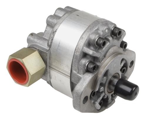
The unit is designed to look like front-mounted tractor weights but actually adds less than 150 lbs. to the front of the tractor. The unit holds a little over 5 gal. of hydraulic oil. A 9 gpm vane pump is embedded inside the reservoir.
Once installed, the tractor has hydraulic power whether or not the clutch is engaged. Most older model tractors have low or limited internal pump flow the hydraulics only work as long as the clutch is engaged.
"The 9gpm pump has enough flow to run most any combination of hydraulic applications, independent of the tractor"s internal hydraulics. A side benefit is having the reservoir on the front of the tractor to give added weight to the front. The unit is as wide as the tractor hood and extends about 8 in. past the grill," says Jackson.
He offers a wide range of hydraulic valves and remotes to match the system, which can be used for log splitters, dump trailers, grain augers, stump grinders, and even add-on power steering.
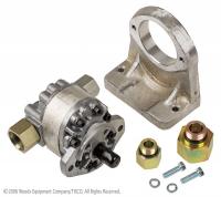
Inventor Roland Jackson is starting out with Fords (9N, 8N, 2N, NAA, 600 Series, 800 Series and early 1000 Series). However, he will soon be adding other models since the hydraulics are the same. Only the mounting brackets are different.
Add-On "Live Hydraulics" For Older Model Tractors TRACTORS Hydraulics 30-1-32 This new front-mounted hydraulic system, recently introduced by Jackson Power Steering, is designed to give older tractors a "live hydraulics" system that"s reliable, strong and trouble-free. The unit is designed to look like front-mounted tractor weights but actually adds less than 150 lbs. to the front of the tractor. The unit holds a little over 5 gal. of hydraulic oil. A 9 gpm vane pump is embedded inside the reservoir. Once installed, the tractor has hydraulic power whether or not the clutch is engaged. Most older model tractors have low or limited internal pump flow the hydraulics only work as long as the clutch is engaged. "The 9gpm pump has enough flow to run most any combination of hydraulic applications, independent of the tractor"s internal hydraulics. A side benefit is having the reservoir on the front of the tractor to give added weight to the front. The unit is as wide as the tractor hood and extends about 8 in. past the grill," says Jackson.He offers a wide range of hydraulic valves and remotes to match the system, which can be used for log splitters, dump trailers, grain augers, stump grinders, and even add-on power steering.Inventor Roland Jackson is starting out with Fords (9N, 8N, 2N, NAA, 600 Series, 800 Series and early 1000 Series). However, he will soon be adding other models since the hydraulics are the same. Only the mounting brackets are different.The kit includes the reservoir, embedded pump, mounting brackets, crankshaft drive kit, and instructions. Sells for $1,495 plus shipping.Contact: FARM SHOW Followup, Jackson Power Steering, Rt. 2, Box 220, Jetmore, Kan. 67854 (ph 620 357-6546; sales@jacksonpowersteering.com).

The present invention relates to utility vehicles, such as industrial or agricultural tractors. Particularly, the invention relates to tractors having one or more hydraulically powered attachments.
Utility vehicles typically include an internal combustion engine, which delivers power to a transmission and ultimately to a wheel for traction, and also delivers power to pressurize hydraulic fluid, via one or more pumps, to operate hydraulic tools or implements.
For example, a tractor may have three hydraulic pumps driven from the engine. A first pump may provide pressurized hydraulic fluid to charge a steering cylinder of the vehicle. A second or “main” pump is usually fixed directly to the crankshaft of the engine and may be used to charge pressurized hydraulic fluid to the loader and the backhoe hydraulic cylinders.
A third or “auxiliary” pump may generate pressurized hydraulic fluid to charge a power takeoff clutch pack and at least one hydraulic cylinder which operates a three point hitch or “rockshaft.” The power takeoff is a shaft that is rotated by the vehicle transmission and is used for supplying rotational power to tools, such as mower decks, where rotation is required.
In small utility tractors, the first or steering pump typically requires about 1.4 to about 8 horsepower, depending on steering demand, and about 22 L/min (about 6 gallons per minute) of hydraulic fluid. The second or “main” pump typically requires about 3.2 to about 21.3 horsepower, depending on demand from loader or backhoe hydraulic systems, and about 46 L/min (about 12 gallons per minute) of hydraulic fluid. The third or “auxiliary” pump typically requires about 1 to about 9.5 horsepower, depending on demand from the rockshaft circuit, and about 20 L/min (about 5 gallons per minute) of hydraulic fluid. The engine for a small utility tractor typically delivers about 25 to 50 horsepower.
When a hydraulically powered attachment such as a sweeper, snow thrower, breaker, auger or cold planer is attached to a utility vehicle, the rockshaft may not be needed, nor is it practically operable. The present inventors have recognized the desirability of diverting hydraulic fluid that would otherwise supply the rockshaft when an attachment such as a sweeper, snow thrower, breaker, auger or cold planer is used. Furthermore, the present inventors have recognized the desirability of using the circulating hydraulic fluid otherwise available to the rockshaft to improve the effectiveness and efficiency of the utility vehicle.
Hydraulically powered attachments such as a sweeper, snow thrower, breaker, auger or cold planer are typically attached to the utility vehicle loader in place of the loader bucket. These attachments may be raised and positioned using the boom and bucket hydraulic cylinders.
The present inventors have recognized that a proper balance of available engine horsepower directed to the various tractor functions at the proper time is required for best operation of the machine. For example, U.S. Pat. No. 6,672,399 assigned to Deere and Company of Moline, Ill. relates to a method and apparatus for diverting pressurized hydraulic fluid, otherwise available to a utility vehicle rockshaft system, to be used by a backhoe hydraulic system.
While the loader is in use, the transmission must necessarily also be in use simultaneously. As such, it is desirable to limit the available horsepower consumed in the operation of the loader while demands are placed on the transmission, to prevent the engine from stalling. Furthermore, it is desirable to limit the hydraulic flow to the boom and bucket circuits so that the boom and bucket do not move too fast, but move at an appropriate rate.
The inventors also have recognized that hydraulically powered attachments such as a sweeper, snow thrower, breaker, auger or cold planer are used without high demand on the transmission, backhoe, rockshaft, or steering circuits. Furthermore, the inventors have recognized that it would be desirable to utilize additional flow from tractor hydraulic systems which are sitting idle while such an attachment is in use.
The present invention provides an apparatus for diverting pressurized hydraulic fluid, otherwise available to a utility vehicle rockshaft, to be used by a hydraulically powered attachment such as a sweeper, snow thrower, breaker, auger or cold planer. Particularly, the invention provides a method and apparatus for diverting pressurized hydraulic fluid from the rockshaft system to be available to a hydraulically powered attachment. Additionally, the invention provides a method and apparatus to divert pressurized hydraulic fluid for an attachment without reducing tractive horsepower the loader needs when it is in use.
The apparatus of the invention may be advantageously accomplished by use of an auxiliary diverter valve connected to the auxiliary pump. The auxiliary diverter valve can direct pressurized hydraulic fluid from the auxiliary pump to either the backhoe system, the rockshaft system, or the auxiliary circuit of the loader hydraulic system.
The auxiliary diverter valve may be connected to a mid-inlet position of the loader hydraulic system. Pressurized hydraulic fluid from the auxiliary pump may be available to the auxiliary circuit of the loader hydraulic system, and not to the boom and bucket circuits. Additional hydraulic flow is made available to an attachment such as a sweeper, snow thrower, breaker, auger or cold planer, allowing for faster movement of the operating cylinders or other hydraulic devices of the attachment, and thus faster and/or more efficient operation of the attachment.
FIG. 1 illustrates utility vehicle 20 such as a tractor with an attachable rear-mounted implement, such as backhoe 24, and a front mounted loader assembly 48. Utility vehicle 20 may include cab or operator"s station 28 including seat 32, steering wheel 34, and loader controls 36. The loader controls may include a selective control valve which may serve a single function or several functions. The cab may be supported on chassis 42 which is supported on front wheels 44 and larger rear wheels 46. The invention may be used with any size and type utility tractor, but is particularly useful for small utility tractors of the general size and type shown in FIG. 1.
The loader assembly may include bucket 81 and boom 82. Hydraulic cylinder 83 may raise and lower the boom, and hydraulic cylinder 84 may actuate the bucket between load holding and dumping positions. Cylinders 83, 84 may be double-acting.
Various hydraulically powered auxiliary attachments such as a sweeper, snow thrower, breaker, auger or cold planer may be attached to the vehicle loader. For example, as shown in FIG. 2, the loader bucket may be removed so that snow thrower 61 may be attached to the boom 81 at the front end of tractor 20 in place of the bucket. The hydraulically powered attachment may have a hydraulic motor connected by fluid lines to the auxiliary circuit of the loader hydraulic system.
The auxiliary circuit of the loader hydraulic system may be served by a third or auxiliary control valve 179 shown in FIG. 3. The third or auxiliary control valve also may be a spool or cartridge valve in a mono block or bolted together with the boom and bucket control valves 177 and 178, and also may be controlled using loader controls 36. Alternatively, the auxiliary attachment may be served by an auxiliary control valve that is a separate or “add-on” device, not in a mono body with the boom and bucket control valves.
FIG. 3 illustrates hydraulic system 120 in one embodiment of the invention. Hydraulic system 120 may be charged by three pumps. Steering pump 124 and auxiliary pump 126 may be driven by the auxiliary drive of engine 130. Main pump 134 may be driven by the crankshaft of engine 130.
In one embodiment, steering pump 124 may charge power steering system 142 and ultimately powers steering cylinder 144. Hydraulic fluid out of steering system 142 may charge hydrostatic transmission 148 which transfers power from the engine to the utility vehicle gear train.
In one embodiment, main pump 134 may charge loader hydraulic system 166 which may include a loader selective control valve, and backhoe hydraulic system 168 which may include a backhoe selective control valve. The loader selective control valve may include a lever which operates the first or boom control valve 177 and the second or bucket control valve 178. The first or boom control valve 177 is part of the boom circuit which may include one or more double acting hydraulic cylinders used to raise or lower the boom. The second or bucket control valve is part of the bucket circuit which may include hydraulic cylinders to control movements of the bucket. Similarly, the backhoe selective control valve may include a lever which operates control valves connected to hydraulic cylinders which control movements of the backhoe, including cylinders for the bucket, dipper, stabilizer, boom and swing.
In one embodiment, auxiliary pump 126 may charge power takeoff system clutch pack 156, and either rockshaft hydraulic system 162, backhoe hydraulic system 168, or the auxiliary circuit of loader hydraulic system 166.
In one embodiment, when the auxiliary pump is connected to rockshaft hydraulic system 162, the pump may direct hydraulic fluid through a rockshaft selective control valve which powers at least one rockshaft hydraulic cylinder. The hydraulic cylinder(s) may control vertical and/or attitude and/or pitch adjustment of the three point hitch. When the auxiliary pump is connected to backhoe hydraulic system 168, the pump may direct hydraulic fluid through a backhoe selective control valve which may include control valves that power several hydraulic cylinders.
When the auxiliary pump is connected to auxiliary control valve 179, the pump may direct hydraulic fluid through an auxiliary hydraulic circuit of the loader hydraulic system. The auxiliary circuit include auxiliary control vale 179 and one or more valves 202, 203 that may be coupled to hydraulically powered attachments such as a sweeper, snow thrower, breaker, auger or cold planer. The attachment may have a hydraulic motor. In one embodiment, the attachment may be operated by use of a loader selective control valve.
In one embodiment, an auxiliary diverter valve in the form of spool or cartridge valve 200 may be hydraulically connected to pressurized hydraulic fluid from auxiliary pump 126. The auxiliary diverter valve may have several positions including a first position to deliver pressurized hydraulic fluid to rockshaft hydraulic system 162, a second position to deliver pressurized hydraulic fluid to backhoe hydraulic system 168, and a third position to deliver pressurized hydraulic fluid to auxiliary control valve 179 of the loader hydraulic system.
By diverting hydraulic fluid to the auxiliary circuit of the loader hydraulic system, the auxiliary pump may be used to increase total pump capacity to a hydraulically powered attachment such as a sweeper, snow thrower, breaker, auger or cold planer. The auxiliary pump previously represented unused capacity during operation of those hydraulically powered attachments.
The size of pump 134 is typically selected to correspond to the total horsepower demand of the front loader, via loader hydraulic system 166. The engine is typically sized to provide reserve horsepower over the demand of the loader to power the hydrostatic transmission during loader work, when the backhoe or other attachments are not in use. Thus, according to one embodiment of the invention, sufficient engine horsepower is available to drive both pumps 126, 134 to supply an attachment such as a sweeper, snow thrower, breaker, auger or cold planer with increased hydraulic capacity. By diverting flow from the auxiliary pump to the auxiliary circuit, the overall horsepower required by the vehicle may be reduced. The invention may therefore be particularly advantageous to retrofit existing utility vehicles or existing designs for utility vehicles.
In one embodiment, the auxiliary diverter valve may have a mid-inlet connection position to the loader hydraulic system so that hydraulic flow from the auxiliary pump is available only to the third or auxiliary control valve, and not to the first or boom control valve or to the second or bucket control valve of the loader hydraulic system. Attachments such as a sweeper, snow thrower, breaker, auger or cold planer typically do not use high hydraulic pressures, and do not require high tractive horsepower from the vehicle hydrostatic transmission. In contrast, the loader boom and bucket circuits require high pressures and, during loader operation, high tractive horsepower is needed from the vehicle.
Thus, hydraulic flow from the auxiliary pump may be diverted to the auxiliary circuit of the loader hydraulic system when an attachment is used. With additional flow from the auxiliary pump, total hydraulic flow available to the attachment may be at least about 20% higher than the hydraulic flow from the main pump alone. For example, in one embodiment, with additional flow from the auxiliary pump, total hydraulic flow available to an attachment may be about 60 L/min (about 16 gallons per minute), compared to about 46 L/min (12 gallons per minute) from the main pump alone.
In accordance with one embodiment of the invention, hydraulic flow from the auxiliary pump is not diverted to the boom or bucket control valves of the loader hydraulic system. As a result, sufficiently high tractive horsepower remains available when the loader is used so that the vehicle"s engine will not stall out.
In one embodiment, auxiliary diverter valve 200 may be connected via fluid line 201 to a mid-inlet position of the loader hydraulic system. In this embodiment, fluid line 201 is connected downstream of boom and bucket control valves 177, 178. For example, fluid line 201 may be connected to a neutral core line between the bucket or boom control valves and auxiliary control valve 179. In this embodiment, hydraulic flow from the auxiliary pump through the auxiliary diverter valve may be available to the auxiliary control valve and auxiliary circuit only.
In an alternative embodiment, hydraulic flow from the auxiliary pump through the auxiliary diverter valve also may be available to the backhoe hydraulic system. For example, the auxiliary diverter valve may have only two positions, i.e., a first position directing hydraulic fluid to the rockshaft hydraulic system, and a second position directing hydraulic fluid to either the backhoe hydraulic system or the auxiliary circuit of the loader hydraulic system. In this alternative embodiment, the auxiliary control valve may be used to select either the backhoe and the auxiliary circuit of the loader hydraulic system. As a result, fluid line 204 may not be needed for this alternative embodiment.
In one embodiment, sufficient flow from the auxiliary pump may be diverted to the auxiliary control valve and auxiliary circuit so that most of the engine power is provided to the hydraulically powered attachment. For example, in one embodiment, about 75 percent of the available engine horsepower may be available for the main and auxiliary hydraulic pumps when a hydraulically powered attachment is used. In contrast, when the loader is being used, only about 50 percent of the available engine horsepower may be available to the main hydraulic pump, with the remainder may be available as tractive horsepower. When the rockshaft is in use, the auxiliary pump uses only about 25 percent of the available engine horsepower. These examples are representative for a small utility tractor that are capable of reducing tractive power if the engine slows excessively due to the loader hydraulic circuits.

Check that the pump shaft is rotating. Even though coupling guards and C-face mounts can make this difficult to confirm, it is important to establish if your pump shaft is rotating. If it isn’t, this could be an indication of a more severe issue, and this should be investigated immediately.
Check the oil level. This one tends to be the more obvious check, as it is often one of the only factors inspected before the pump is changed. The oil level should be three inches above the pump suction. Otherwise, a vortex can form in the reservoir, allowing air into the pump.
What does the pump sound like when it is operating normally? Vane pumps generally are quieter than piston and gear pumps. If the pump has a high-pitched whining sound, it most likely is cavitating. If it has a knocking sound, like marbles rattling around, then aeration is the likely cause.
Cavitation is the formation and collapse of air cavities in the liquid. When the pump cannot get the total volume of oil it needs, cavitation occurs. Hydraulic oil contains approximately nine percent dissolved air. When the pump does not receive adequate oil volume at its suction port, high vacuum pressure occurs.
This dissolved air is pulled out of the oil on the suction side and then collapses or implodes on the pressure side. The implosions produce a very steady, high-pitched sound. As the air bubbles collapse, the inside of the pump is damaged.
While cavitation is a devastating development, with proper preventative maintenance practices and a quality monitoring system, early detection and deterrence remain attainable goals. UE System’s UltraTrak 850S CD pump cavitation sensor is a Smart Analog Sensor designed and optimized to detect cavitation on pumps earlier by measuring the ultrasound produced as cavitation starts to develop early-onset bubbles in the pump. By continuously monitoring the impact caused by cavitation, the system provides a simple, single value to trend and alert when cavitation is occurring.
The oil viscosity is too high. Low oil temperature increases the oil viscosity, making it harder for the oil to reach the pump. Most hydraulic systems should not be started with the oil any colder than 40°F and should not be put under load until the oil is at least 70°F.
Many reservoirs do not have heaters, particularly in the South. Even when heaters are available, they are often disconnected. While the damage may not be immediate, if a pump is continually started up when the oil is too cold, the pump will fail prematurely.
The suction filter or strainer is contaminated. A strainer is typically 74 or 149 microns in size and is used to keep “large” particles out of the pump. The strainer may be located inside or outside the reservoir. Strainers located inside the reservoir are out of sight and out of mind. Many times, maintenance personnel are not even aware that there is a strainer in the reservoir.
The suction strainer should be removed from the line or reservoir and cleaned a minimum of once a year. Years ago, a plant sought out help to troubleshoot a system that had already had five pumps changed within a single week. Upon closer inspection, it was discovered that the breather cap was missing, allowing dirty air to flow directly into the reservoir.
A check of the hydraulic schematic showed a strainer in the suction line inside the tank. When the strainer was removed, a shop rag was found wrapped around the screen mesh. Apparently, someone had used the rag to plug the breather cap opening, and it had then fallen into the tank. Contamination can come from a variety of different sources, so it pays to be vigilant and responsible with our practices and reliability measures.
The electric motor is driving the hydraulic pump at a speed that is higher than the pump’s rating. All pumps have a recommended maximum drive speed. If the speed is too high, a higher volume of oil will be needed at the suction port.
Due to the size of the suction port, adequate oil cannot fill the suction cavity in the pump, resulting in cavitation. Although this rarely happens, some pumps are rated at a maximum drive speed of 1,200 revolutions per minute (RPM), while others have a maximum speed of 3,600 RPM. The drive speed should be checked any time a pump is replaced with a different brand or model.
Every one of these devastating causes of cavitation threatens to cause major, irreversible damage to your equipment. Therefore, it’s not only critical to have proper, proactive practices in place, but also a monitoring system that can continuously protect your valuable assets, such as UE System’s UltraTrak 850S CD pump cavitation senor. These sensors regularly monitor the health of your pumps and alert you immediately if cavitation symptoms are present, allowing you to take corrective action before it’s too late.
Aeration is sometimes known as pseudo cavitation because air is entering the pump suction cavity. However, the causes of aeration are entirely different than that of cavitation. While cavitation pulls air out of the oil, aeration is the result of outside air entering the pump’s suction line.
Several factors can cause aeration, including an air leak in the suction line. This could be in the form of a loose connection, a cracked line, or an improper fitting seal. One method of finding the leak is to squirt oil around the suction line fittings. The fluid will be momentarily drawn into the suction line, and the knocking sound inside the pump will stop for a short period of time once the airflow path is found.
A bad shaft seal can also cause aeration if the system is supplied by one or more fixed displacement pumps. Oil that bypasses inside a fixed displacement pump is ported back to the suction port. If the shaft seal is worn or damaged, air can flow through the seal and into the pump’s suction cavity.
As mentioned previously, if the oil level is too low, oil can enter the suction line and flow into the pump. Therefore, always check the oil level with all cylinders in the retracted position.
If a new pump is installed and pressure will not build, the shaft may be rotating in the wrong direction. Some gear pumps can be rotated in either direction, but most have an arrow on the housing indicating the direction of rotation, as depicted in Figure 2.
Pump rotation should always be viewed from the shaft end. If the pump is rotated in the wrong direction, adequate fluid will not fill the suction port due to the pump’s internal design.
A fixed displacement pump delivers a constant volume of oil for a given shaft speed. A relief valve must be included downstream of the pump to limit the maximum pressure in the system.
After the visual and sound checks are made, the next step is to determine whether you have a volume or pressure problem. If the pressure will not build to the desired level, isolate the pump and relief valve from the system. This can be done by closing a valve, plugging the line downstream, or blocking the relief valve. If the pressure builds when this is done, there is a component downstream of the isolation point that is bypassing. If the pressure does not build up, the pump or relief valve is bad.
If the system is operating at a slower speed, a volume problem exists. Pumps wear over time, which results in less oil being delivered. While a flow meter can be installed in the pump’s outlet line, this is not always practical, as the proper fittings and adapters may not be available. To determine if the pump is badly worn and bypassing, first check the current to the electric motor. If possible, this test should be made when the pump is new to establish a reference. Electric motor horsepower is relative to the hydraulic horsepower required by the system.
For example, if a 50-GPM pump is used and the maximum pressure is 1,500 psi, a 50-hp motor will be required. If the pump is delivering less oil than when it was new, the current to drive the pump will drop. A 230-volt, 50-hp motor has an average full load rating of 130 amps. If the amperage is considerably lower, the pump is most likely bypassing and should be changed.
Figure 4.To isolate a fixed displacement pump and relief valve from the system, close a valve or plug the line downstream (left). If pressure builds, a component downstream of the isolation point is bypassing (right).
The most common type of variable displacement pump is the pressure-compensating design. The compensator setting limits the maximum pressure at the pump’s outlet port. The pump should be isolated as described for the fixed displacement pump.
If pressure does not build up, the relief valve or pump compensator may be bad. Prior to checking either component, perform the necessary lockout procedures and verify that the pressure at the outlet port is zero psi. The relief valve and compensator can then be taken apart and checked for contamination, wear, and broken springs.
Install a flow meter in the case drain line and check the flow rate. Most variable displacement pumps bypass one to three percent of the maximum pump volume through the case drain line. If the flow rate reaches 10 percent, the pump should be changed. Permanently installing a flow meter in the case drain line is an excellent reliability and troubleshooting tool.
Ensure the compensator is 200 psi above the maximum load pressure. If set too low, the compensator spool will shift and start reducing the pump volume when the system is calling for maximum volume.
Performing these recommended tests should help you make good decisions about the condition of your pumps or the cause of pump failures. If you change a pump, have a reason for changing it. Don’t just do it because you have a spare one in stock.
Conduct a reliability assessment on each of your hydraulic systems so when an issue occurs, you will have current pressure and temperature readings to consult.
Al Smiley is the president of GPM Hydraulic Consulting Inc., located in Monroe, Georgia. Since 1994, GPM has provided hydraulic training, consulting and reliability assessments to companies in t...

The MT7 tractor delivers peak performance to get the job done, no matter how severe the conditions. Whether clearing sidewalks, mowing grass with one of our large commercial mowers, cutting ditches with our boom flail mower, grinding sidewalk concrete or performing any one of the many other maintenance duties assigned, you can count on the tough, rugged and powerful MT7 to meet the challenge.
Another reason for choosing this engine was to be ahead of the mandated regulations from EPA, CARB, and NRC. Since the Tier 4 Interim engines are only short lived engines, which many if not most manufacturers decided just to skip past and go straight to the Tier 4 Final, it did not make sense to produce a small number of tractors with a Tier 4I (Interim) engine, for obvious reasons. Today, the MT7’s engine has been further updated to a Stage 5.
For decades Trackless has stayed with the most rugged and efficient drivetrain design which consists of a hydrostatic transmission that drives a mechanical transmission. The mechanical transmission has a low gear, high gear and neutral. The mechanical transmission drives the front and rear axles by way of driveshafts. The result is constant, high torque 4 wheel drive. A 10:1 deep reduction planetary is available as an option. With this option, the operator can select any one of four speed ranges, the slowest being 0 to 10 feet per minute, ideal for the cold planers and leaf loader.
The MT7 hydrostatic transmission is a Sauer Danfoss. It is electronically controlled by depressing the electronic foot pedal. There are multiple ramps programmed into the system so that the tractor operates smoothly and maintains traction under all circumstances. There are also multiple ramps programmed for braking when the operator lets off on the foot peddle so that no matter what gear range you are in or how fast you are moving, the dynamic braking from the hydrostatic is just right. However, if an operator wants to stop very quickly, simply touch the service brake pedal and all of the brake ramps become very aggressive and the braking motion feels like that of a high-performance automobile.
The Twin Disc PTO clutch is rated at 200 hp which means it will easily last the life of the tractor. When coupled to any one of our snowblowers the combination of the MT7’s large displacement, high torque engine, oversized PTO clutch and superior traction is unstoppable. No matter how deep, heavy, or contaminated with salt or frozen the snow is, the MT7 and snowblower will chew its way through.
The front and rear axle are Dana 60 type with track lock differentials. The axles are extremely tough and have extra heavy wall tubing and oversized axle shafts. As an option, we offer an electric locking differential for the front axle.
In addition to the front PTO and optional rear PTO, the MT7 also comes standard with two auxiliary hydraulic power circuits. One circuit can power an attachment on the front while the second circuit can independently power a different attachment on the rear: For example, a sweeper on the front and a sand spreader on the rear. The two circuits can also power two independent functions on the front, such as the left wing and right wing on one of our large commercial mowers.
When the weather turns cold and the snow starts to fly, people start to warm up their compact tractors. That’s because the dependability, versatility and affordability of this machine help to make it ideal for a wide variety of tasks, including snow removal. However, to get the most work out of this winter workhorse, many people consider purchasing a snowblower attachment. This addition helps move large volumes of snow quicker than a standard loader bucket. Unfortunately, many people have trouble finding the right unit to meet their needs. The tractor wasn’t originally designed with snowblower attachments in mind and, as a result, some of the available solutions can be awkward for people to operate. Thankfully, manufacturers have made some design improvements over the years, and today there are a wide variety of smart snowblower solutions to accommodate any operator.
The most common and traditional way to mount a snowblower on a tractor is the three-point hitch. This universal hitching system is easy to hook up, and it allows direct access to the tractor’s rear power take-off (PTO) shaft. The PTO transfers full engine horsepower to the snowblower, resulting in reliable, high-performance operation. The rear mount is also the simplest setup available, making it the most cost-effective solution on the market.
Additionally, a rear-mount snowblower allows full use of the tractor’s front loader bucket (if one is equipped). Therefore, the operator can use the front bucket to scrape ice, scoop snow or drag it away from buildings, while using the rear blower to throw the snow. Despite the proven performance of the rear-mount design, there are limitations. The three-point hitch is unable to tip or rotate the snowblower on the go, nor can it raise the blower more than a couple feet off the ground. This makes it difficult to maneuver or chip away at extremely tall drifts. The three-point hitch can’t apply down pressure, so the snowblower always operates in “float” mode, eliminating the ability to scrape ice and hard pack.
Beyond operational issues, most people will agree that it is inconvenient and unnatural to operate a rear-mounted snowblower. Ask anyone if he or she prefers to drive a car forward or in reverse … the answer, of course, will be forward. The same goes for driving a tractor. Even though there may be no roads to follow when blowing snow, it is easier and more comfortable to drive the tractor when facing the direction of operation, rather than looking backward. Obviously, it is uncomfortable to turn around 180 degrees and drive in reverse for extended amounts of time, but it is even more so for people with back or neck problems.
Due to the shortfalls of the rear-mounting system, manufacturers have developed new designs for front-mounted snowblowers, which have become increasingly popular in recent years. With options for mechanical and hydraulic drives, there are units available to meet any need. The very first front-mounted snowblowers to be introduced were mechanically driven. Looking to take advantage of the PTO system, engineers developed a special framework to run driveshafts underneath the tractor, extending from the rear PTO to the front of the tractor, where the blower was mounted.
Through this system, operators enjoy the enhanced visibility and ease of use of a front-mounted unit, while benefiting from the reliability and full engine power provided by the PTO drive. However, this approach comes with drawbacks of its own. The first drawback is price. The complex design of this setup requires a lot of parts to route the mechanical drive and mount the snowblower on the front of the tractor. Understandably, this drives up the cost, making it the most expensive option available for a front-mounted unit.
When installing a mechanically driven front-mounted snowblower, the loader assembly must be removed from the tractor. And if the tractor is equipped with a grill guard, that must also be removed in order to accommodate the blower. In this case, switching between the loader and snowblower is such a time-consuming task that it isn’t feasible to do often. Next, the movement of the snowblower is restricted by the PTO drive. The unit can’t be tipped up or down, and it can only be raised a foot or less off the ground. The ground clearance of the tractor is also compromised, due to the added framework that can easily hang up on uneven terrain.
The main issue with the compact tractors is getting full hydraulic power to the front of the tractor. Unlike skid steers, tractors don’t have an accessible hydraulic system at the front of the machine. Therefore, some manufacturers have developed special kits that contain a standalone hydraulic pump, filter, relief valve, reservoir and cooler. The kits attach to the rear of the tractor, and the PTO powers the system. Hydraulic hoses are then routed from the kit to the front of the tractor and hooked up to the snowblower.
Unfortunately, the extra kit hangs off the back end of the tractor, giving it a longer footprint and hindering the ability to hook up other implements at the rear. It’s fairly common for operators to forget about the added length, so many people damage the hydraulic kit by backing into trees, buildings or other obstacles.
The latest option is to tie into the tractor’s hydraulic system, so the operator does not need to purchase a separate standalone hydraulic kit. The snowblower borrows a small percentage of hydraulic oil from the loader circuit, and the oil is then filtered and cooled through the tractor’s hydraulic system. By taking advantage of the tractor’s hydraulics, this maximizes simplicity and helps ensure the oil is kept at proper operating temperature.
The ideal method of powering this system is to couple a hydraulic pump to the mid-mount PTO shaft located underneath the tractor, between the front and rear axles. Unlike the rear PTO shaft, which turns at 540 rpm, the mid-mount PTO turns at approximately 2,000 rpm — a more appropriate speed to power the hydraulic pump. If a mid-mount shaft is unavailable, a step-up gearbox and pump can be mounted on the rear 540-rpm PTO.
If purchasing a hydraulically powered snowblower, ensure the manufacturer offers a properly rated pump that will produce full engine horsepower. For example, if the tractor’s engine has 35 hp, make sure the pump provided with the snowblower is rated for at least 35 hp. If not, the hydraulic system will operate at less power than the engine is capable of producing.
A major benefit to loader-mounted hydraulically powered snowblowers is that they typically use the universal skid steer quick-attach system. This allows full articulation of the loader arms. Because of this loader-mounted feature, the operator can tilt the angle of the snowblower, or he can raise the unit as high as the tractor allows.
Some of the front-mounted snowblowers on the market, however, are not adapted for use on the loader, and they have the same configuration as a rear-mounted blower. For instance, some front-mounted blowers contain a gearbox located directly behind the auger and impeller (the same design as a rear-mounted one). However, this significantly extends the length of the unit beyond the loader arms. Better suited designs are compact with inline auger and impeller drives. This keeps the snowblower’s weight closer to the tractor for maximum leverage and maneuverability.

When a hydraulic system fails, finding the source of the problem can be a challenge. Though hydraulic systems primarily consist of a sump, motor, pump, valves, actuators and hydraulic fluid, any of these parts could be the source of failure. That"s not to mention the additional potential for failure through human error and faulty maintenance practices. If your system fails, you need to know why it fails, how to find the failure and how to keep it running smoothly in the future, all while keeping personnel safe.
It"s often easy to tell when a hydraulic system fails — symptoms can include high temperatures, low pressure readings and slow or erratic operation are glaring problems. But what are the most common causes of hydraulic systems failures? We can trace most hydraulic issues back to a few common causes, listed below.
Air and water contamination are the leading causes of hydraulic failure, accounting for 80 to 90% of hydraulic failures. Faulty pumps, system breaches or temperature issues often cause both types of contamination.
Air contamination is the entrance of air into a hydraulic system and consists of two types — aeration and cavitation. Both can cause severe damage to the hydraulic system over time by wearing down the pump and surrounding components, contaminating hydraulic fluids and even overheating the system. Although we are not pump manufacturers, we know it is essential to be aware of these types of contamination and how to identify their symptoms.
Cavitation:Hydraulic oil consists of about 9% dissolved air, which the pump can pull out and implode, causing pump problems and damage to the pump and to other components in a hydraulic system over time. You can identify this problem if your hydraulic pump is making a whining noise.
Aeration:Aeration occurs when air enters the pump cavity from an outside source. Usually, loose connections or leaks in the system cause this issue. Aeration also creates a sound when the pump is running, which sounds like knocking.
Water contamination is also a common problem in hydraulic systems, often caused by system leaks or condensation due to temperature changes. Water can degrade hydraulic components over time through oxidation and freeze damage. A milky appearance in hydraulic fluid can help you identify water contamination.
Fluid oxidization: Extreme heat can cause hydraulic fluid to oxidize and thicken. This fluid thickening can cause buildups in the system that restrict flow, but can also further reduce the ability of the system to dissipate heat.
Fluid thickening:Low temperatures increase the viscosity of hydraulic oil, making it harder for the oil to reach the pump. Putting systems under load before the oil reaches 70 degrees or more can damage the system through cavitation.
Fluid levels and quality can affect hydraulic system performance. Low fluid levels and inappropriate filtration can result in air contamination, while fluid contamination can cause temperature problems. Leaks can further exacerbate both issues.
Using the correct type of fluid is also essential, as certain hydraulic oils are compatible with specific applications. There are even oil options that offer higher resistance to temperature-related problems. Some oils even offer anti-wear and anti-foam additives to help prevent against wear and air contamination, respectively.
Human error is the base cause of many hydraulic system problems. Some of the most common errors that may result in your hydraulic pump not building pressure include the following.
Faulty installations: Improper installation of any component in a hydraulic system can result in severe errors. For example, the pump shaft may be rotating in the wrong direction, negatively affecting pressure buildup, or pipes may be incorrectly fitted, resulting in leaks.
Incompatible parts: An inexperienced installer may put mismatched components together, resulting in functional failures. For example, a pump may have a motor that runs beyond its maximum drive speed.
Improper maintenance or usage:Using systems outside their operational capabilities or failing to perform regular maintenance are some of the most common causes of hydraulic system damage, but are easy to rectify through updated maintenance policies and training.
The sources of system failures can be tricky to identify, but some hydraulic troubleshooting steps can help narrow down the options. So how do you troubleshoot a hydraulic system? Here are some of the fundamentals.
Check the pump: Take the pump assembly apart and assess all parts to ensure that they are functional and installed correctly. The most common problem areas include the pump shaft, coupling and filter.
Check the fluids:Check the level, color and viscosity of the hydraulic oil to ensure it meets specifications and has not become contaminated. Low hydraulic fluid symptoms include pressure or power loss. When in doubt, drain and replace the fluids.
Check the seals: Look for evidence of any fluid leakage around your hydraulic system"s seals, especially the shaft seal. Leakage can indicate worn-out or blown seals that can cause malfunctions with pumps, motors and control valves.
Check the filters: Ensure filters are clear of plugs and blockages. Common clogged hydraulic filter symptoms include sluggish operation and noisy operation.
Hydraulic system issues are inevitable at some point. However, simple steps can help you avoid these issues and increase the longevity of your hydraulic system. On top of effective troubleshooting, you can prevent hydraulic system failure by taking the following steps.
Follow specifications: We can trace the most common hydraulic system issues back to fundamental system problems like incompatible or improperly installed parts. For this reason, it"s essential to always double-check specifications to ensure your purchased parts can work together seamlessly.
On top of these steps, look into hydraulic system products that are specifically designed to help prevent failures. One such product is Bear-Loc® by York Precision. This innovative locking actuator is a safe, reliable feature for hydraulic components, automatically locking when sleeve pressure is relieved, preventing movement if a hydraulic system fails. This way, your can protect your personnel from injuries related to hydraulic failures. Even better, York Precision offers in-house design, engineering expertise and machining and manufacturing capabilities to produce a hydraulic locking device that meets your exact specifications.
Regularly review hydraulic system maintenance, always following manufacturer recommendations and industry best practices. Also, consider the storage condition, external influences, working pressure and usage frequency of your system to tailor your maintenance schedule and procedures.
Daily tasks:Take care of a few simple daily checks to avoid issues. For example, personnel should check the oil levels, hoses and connections and listen to the pump for abnormal sounds.
Be mindful of location:Do not stand at endpoints while working on hydraulic systems. This safety measure can help prevent loss of limb and life, as there is a lot of pressure built up in these areas that can release and result in life-threatening situations.
The best safety measures, however, are to perform excellent maintenance and use high-quality parts. If you"re looking for a quality hydraulic component manufacturer, York Precision Machining & Hydraulics can help.

The N Tractor Club is a place to share information about Ford N Series Tractors (9N-2N-8N-NAA) and other topics of interest. If you are new tractor owner, you will find our club to be very newbie-friendly, we have an environment that makes it easy to ask new-owner-questions and get the support you need to safely use and properly maintain your tractor and implements.


 8613371530291