
tractor hydraulic pump pressure factory
Hydraulics is a term used for the study of liquids and how they function. In engineering, the term hydraulic systems refer to those that work by using pressurized fluid to power an engine. These systems put pressure on a small amount of fluid to generate large amounts of power. The discovery of the use of hydraulics has enabled us to accomplish significant work, such as lifting heavy loads and turning huge shafts with minimum input through a mechanical linkage.
Hydraulic power systems are more flexible than mechanical and electrical systems and produce more power than systems of equal size. They also provide rapid and accurate responses to controls. As a result, hydraulic power systems are extensively used in modern aircraft, automobiles, heavy industrial machinery, and many kinds of machine tools. In this article, we will particularly discuss the hydraulic system in a tractor.
The hydraulic pump draws up oil from the oil reservoir and sends it to the control valve under high pressure. From there, the oil goes to the hydraulic cylinder to operate the piston which in turn raises the lifting arms. The hydraulic pump is operated by suitable gears that are connected with the engine.
There are two types of arrangements for storing hydraulic oil:There is a common oil reservoir for hydraulic system and the transmission system in some tractors
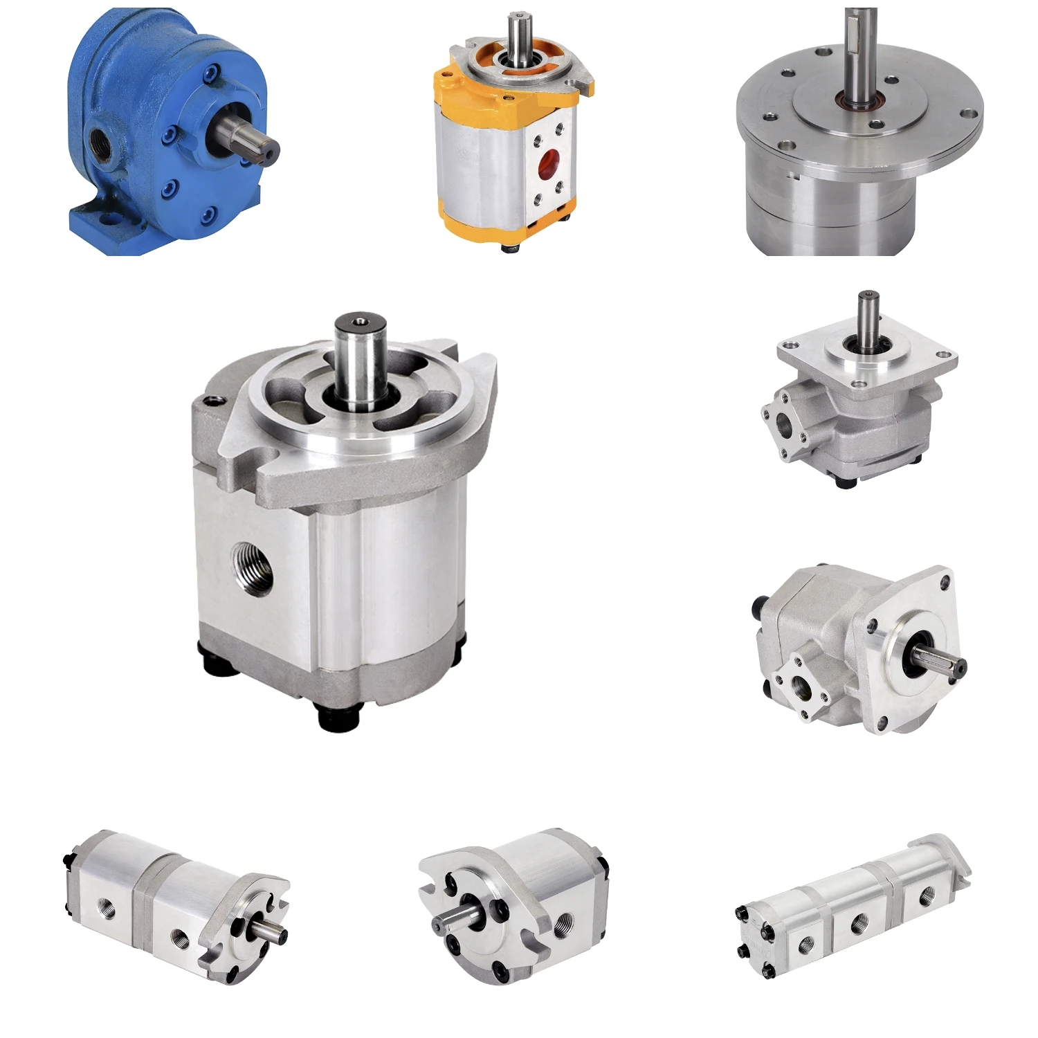
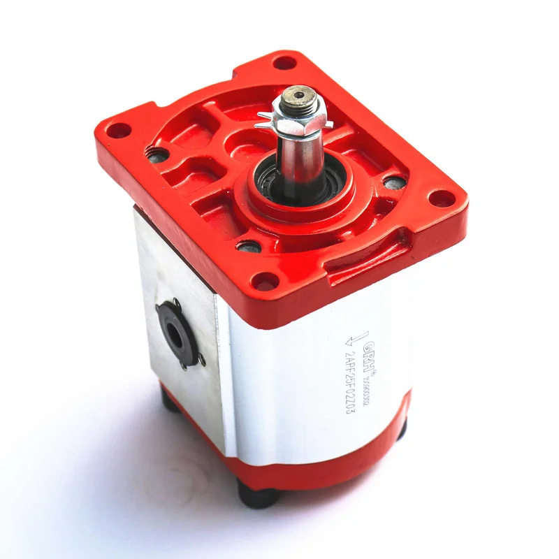
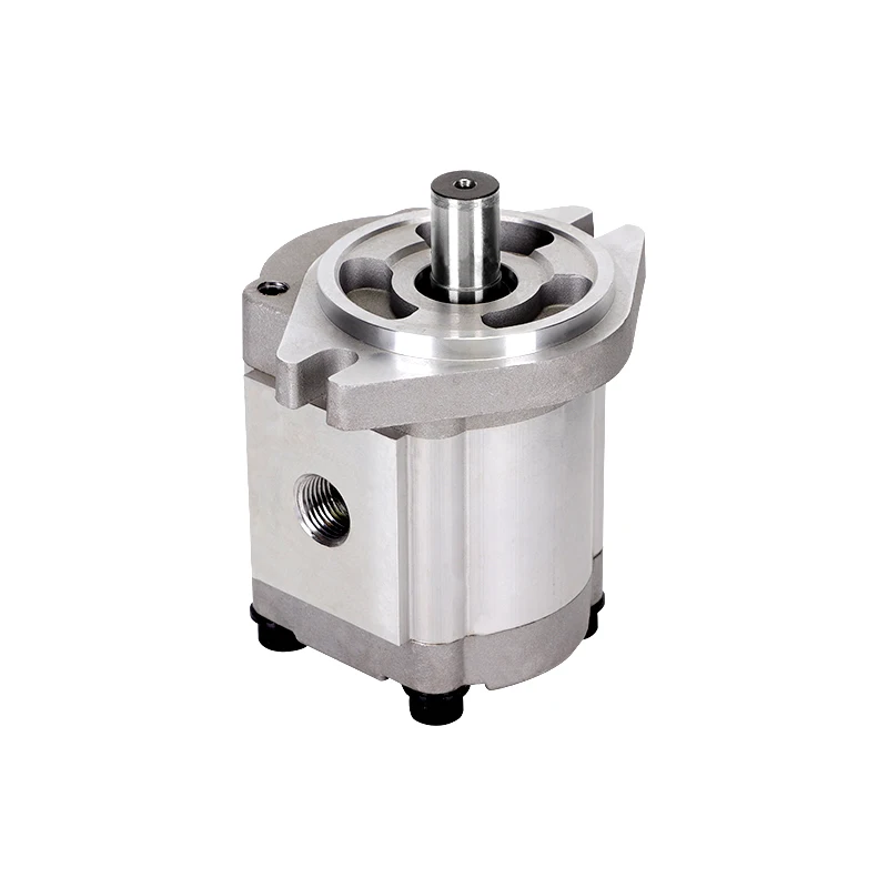
Hydraulic pump:They are of several types, such as gear pump, plunger pump, vane pump, and screw pump. Gear pumps are widely used in tractors because they can flow a large amount of oil in comparison to a plunger pump. The oil pressure in the pump varies from 150 to 200 kg/cm2.
Hydraulic cylinder: It is a bigger cylinder fitted with a piston and a connecting rod, also called a ram cylinder. The piston moves in the hydraulic cylinder and causes reciprocating motion in the cylinder. It is the connecting rod that transmits power from the piston to the lifting arms. Although the lifting arm is raised by hydraulic pressure, it is lowered by its weight.
Hydraulic tank: It is used for storing hydraulic oil. In some tractors, the transmission chamber itself works as a hydraulic tank and the same oil is used for both transmission and hydraulic systems.
Agriculture and allied activities are constantly evolving. With recent advancements in science, agro-based industries are coming up in terrains and locations that were previously unexplored. The topography of these areas has to go through various changes to meet land use standards. Heavy machinery, such as trucks and tractors, has to work in harsh climatic conditions, within a set duration to bring the sites up to speed.
These machines use heavy-duty engines as they are subject to a lot of strenuous work. The resulting friction within the engine has to be reduced to maintain performance and increase life. For engines to become more robust and advanced, hydraulic technology must be at the forefront, as these components are the ones that endure the load in driving the crankshafts and must generate a consistently high power delivery.
At Atrac, we take into account what the future holds for the agriculture and allied industry and constantly endeavor to keep up with those needs. With our state-of-the-art manufacturing and testing facility, we produce high-quality hydraulic parts such as camshafts, control arms, control valves, lift rams, and pistons, that not only meet industry standards but also meet Original Equipment Manufacturer (OEM) specifications. These parts have proved reliable on the field and have stood true to our promise of quality and assurance.

Abnormal noise in hydraulic systems is often caused by aeration or cavitation. Aeration occurs when air contaminates the hydraulic fluid. Air in the hydraulic fluid makes an alarming banging or knocking noise when it compresses and decompresses, as it circulates through the system.
Air usually enters the hydraulic system through the pump’s inlet. For this reason, it is important to make sure pump intake lines are in good condition and all clamps and fittings are tight. Flexible intake lines can become porous with age; therefore, replace old or suspect intake lines. If the fluid level in the reservoir is low, a vortex can develop, allowing air to enter the pump intake.
Check the fluid level in the reservoir, and if low, fill to the correct level. In some systems, air can enter the pump through its shaft seal. Check the condition of the pump shaft seal and if it is leaking, replace it.
Cavitation occurs when the volume of fluid demanded by any part of a hydraulic circuit exceeds the volume of fluid being supplied. This causes the absolute pressure in that part of the circuit to fall below the vapor pressure of the hydraulic fluid. This results in the formation of vapor cavities within the fluid, which implode when compressed, causing a characteristic knocking noise.
The consequences of cavitation in a hydraulic system can be serious. Cavitation causes metal erosion, which damages hydraulic components and contaminates the fluid. In extreme cases, cavitation can cause mechanical failure of system components.
While cavitation can occur just about anywhere within a hydraulic circuit, it commonly occurs at the pump. A clogged inlet strainer or restricted intake line will cause the fluid in the intake line to vaporize. If the pump has an inlet strainer or filter, it is important for it not to become clogged. If a gate-type isolation valve is fitted to the intake line, it must be fully open.
This type of isolation device is prone to vibrating closed. The intake line between the reservoir and pump should not be restricted. Flexible intake lines are prone to collapsing with age; therefore, replace old or suspect intake lines.
Fluid temperatures above 180°F (82°C) can damage seals and accelerate degradation of the fluid. This means that the operation of any hydraulic system at temperatures above 180°F is detrimental and should be avoided. Fluid temperature is too high when viscosity falls below the optimum value for the system’s components. The temperature at which this occurs is dependent on the viscosity grade of the fluid in the system and can be well below 180°F.
High fluid temperature can be caused by anything that either reduces the system’s capacity to dissipate heat or increases its heat load. Hydraulic systems dissipate heat through the reservoir. Therefore, the reservoir fluid level should be monitored and maintained at the correct level. Check that there are no obstructions to airflow around the reservoir, such as a build up of dirt or debris.
It is important to inspect the heat exchanger and ensure that the core is not blocked. The ability of the heat exchanger to dissipate heat is dependent on the flow rate of both the hydraulic fluid and the cooling air or water circulating through the exchanger. Therefore, check the performance of all cooling circuit components and replace as necessary.
When fluid moves from an area of high pressure to an area of low pressure without performing useful work (pressure drop), heat is generated. This means that any component that has abnormal internal leakage will increase the heat load on the system. This could be anything from a cylinder that is leaking high-pressure fluid past its piston seal, to an incorrectly adjusted relief valve. Identify and change-out any heat-generating components.
Air generates heat when compressed. This means that aeration increases the heat load on the hydraulic system. As already explained, cavitation is the formation of vapor cavities within the fluid. These cavities generate heat when compressed. Like aeration, cavitation increases heat load. Therefore, inspect the system for possible causes of aeration and cavitation.
In addition to damaging seals and reducing the service life of the hydraulic fluid, high fluid temperature can cause damage to system components through inadequate lubrication as a result of excessive thinning of the oil film (low viscosity). To prevent damage caused by high fluid temperature, a fluid temperature alarm should be installed in the system and all high temperature indications investigated and rectified immediately.
A reduction in machine performance is often the first indication that there is something wrong with a hydraulic system. This usually manifests itself in longer cycle times or slow operation. It is important to remember that in a hydraulic system, flow determines actuator speed and response. Therefore, a loss of speed indicates a loss of flow.
Flow can escape from a hydraulic circuit through external or internal leakage. External leakage such as a burst hose is usually obvious and therefore easy to find. Internal leakage can occur in the pump, valves or actuators, and unless you are gifted with X-ray vision, is more difficult to isolate.
As previously noted, where there is internal leakage there is a pressure drop, and where there is a pressure drop heat is generated. This makes an infrared thermometer a useful tool for identifying components with abnormal internal leakage. However, temperature measurement is not always conclusive in isolating internal leakage and in these cases the use of a hydraulic flow-tester will be required.
Proactively monitoring noise, fluid temperature and cycle times is an effective way to detect conditions that can lead to costly component failures and unscheduled downtime of hydraulic equipment. In most cases, informed observation is all that is required.

Steiner Tractor Parts proudly offers a wide selection of tractor parts for vintage, old, classic farm tractors. We strive to not only offer the best selection of affordably priced tractor restoration parts, but to preserve the American agricultural heritage by helping you keep your old tractors running.We are focused on meeting all your restoration needs while offering value and quality with every tractor part we deliver.
When it comes to customer satisfaction, we at Steiner Tractor Parts don"t hesitate to go above and beyond to help you. Our website is not just an online store. It is a resource and a community of people who refuse to let our agricultural heritage disappear. We invite you to join us by subscribing to our popular blog, reading our tractor stories and enjoying some tractor trivia.
There are many agricultural tools and machines that employ hydraulics for smooth working. And note that a tractor is among these powerful and sturdy machines that rely or depend on the sheer power of hydraulics.
Many people are familiar with hydraulics and hydraulic systems; however, how many among us really know and comprehend how hydraulics work and operate in the tractor loader? Keep in mind that the components and parts of a typical hydraulic system comprise a reservoir, many valves, and pump. And it’s worth noting that hydraulic control valves and other parts can operate in a system that accurately directs, or controls liquid flow.
Hydraulic control valves for tractor loaders are an irreplaceable part that’s used in various kinds of machines in several industries. For example, it is the basis of activity in agriculture and construction. It is hard to imagine modern excavators, tractors, and loaders without a hydraulic control valve.
We can say that a hydraulic valve is an effective mechanical device that regulates the fluid flow within a specific hydraulic system or circuit. Did you know that you can also use it to completely close a line, or redirect pressurized fluid or even control the degree of flow to specific areas?
Hydraulic valves are usually used in hydraulic power packs in order to direct the fluid either from or to a hydraulic cylinder. Hydraulic valves are important as they help control and regulate the amounts and direction of fluid power in a circuit by closely controlling and tracking the flow rate and pressure in various components of the circuit.
Keep in mind that hydraulic valves in a tractor must be capable of withstanding high degree of fluid pressure. And it’s because the nature of many contemporary hydraulic systems means high pressure values of 3,000 PSI or even more.
Remember that the hydraulic system in the machine has to lift the bale or the load of dirt and the bale fork. So, even a small tractor’s hydraulic system is usually under massive pressure.
As a result, they are usually constructed of iron, or steel. The material should have sufficient strength to withstand continuous and extreme operation under pressurized conditions. Also, the hydraulic reservoir is typically used for storing non-pressurized hydraulic fluid.
Before learning how to add a hydraulic valve to your tractor, you must know and appreciate how a hydraulic system typically works on any tractor. Note that the hydraulic system works with the help of pumps. These pumps are essential and transfer the fluid from the hydraulic system’s big reservoir to the tractor’s hydraulic system.
And this process raises the level of energy. This is done by gradually raising the pressure. And the motor inside your tractor is the primary power source for pumps. The fluid or liquid is under intense pressure and acts on both the piston and rod inside your cylinder.
You should know that each cylinder stroke is important as it converts the fluid power, also called pressure, into valuable mechanical force. The oil level in the reservoir will gradually fall while other parts, such as the piston and rods extend.
On the other hand, when these parts gradually retract and move back, you will see that all the fluid will slowly get back to the reservoir. After that, you will notice the metallic walls of this reservoir start to trigger a drop in the fluid temperature by letting all the heat energy escape. This is crucial as it reduces the total pressure in the reservoir. The operation or mechanics of a tractor’s hydraulic system works mainly based on Pascal’s law.
If you attach a remote hydraulic system in order to make your tractor more efficient, it will give you the opportunity to add many hydraulic accessories. A few of them are a log splitter, hydraulic top link, blades, and hydraulic auger motor. Note that if you used an open centered valve, then the oil will be moving along the standard route to the 3 point until someone pulls the handle on the valve.
After that, the valve may divert the oil to increase or lower your hydraulic accessory. You can reverse the oil or fluid flow to your accessory by pushing the handle in the other direction.
There is no doubt that a hydraulic valve in your tractor loader is among the most integral components in this valuable hydraulic machinery. The valve is crucial. This is because it allows fluid to flow in different directions from either one or multiple sources. It’s worth noting that hydraulic valves in tractor loaders usually have a spool. We can say that the spool is encased in a cylinder that you can control either mechanically or even electrically.
The best thing is that it is simple to turn an old tractor, such as your garden tractor, into a capable earth moving machine or convert its conventional manual lift system to hydraulic. Did you know that adding hydraulics can multiply a tractor’s engine power manifold?
⦁ You should carefully and gradually depressurize the sensitive hydraulic system. It is essential that you consult and go through your specific system documentation to make this step simple.
⦁ Now remove any electrical power or energy source from your system if electric pumps are pressurizing it. You can do this by disconnecting your pump’s power connector or simply pulling its circuit breaker. However, keep in mind that some mechanically driven pumps, like engine-driven pumps, might not have electrical connectors.
⦁ You should remove your old or current valve by removing the current electrical connector. Now place a few buckets underneath the hydraulic valve in a careful manner and then unscrew the bolts and nuts that are leading to the valve.
⦁ Carefully position your valuable hydraulic valve where it will be installed. You should plug the fittings present on it and then cap all the ends of either the tubing system or pipes it will connect to. You should plug all hydraulic lines. These lines may lead to or/and from the valve. Plugging them will minimize the risk of fluid loss. It is best to use plastic plug or aluminum plug that easily screws into the fitting.
⦁ You should supply proper electrical energy if it’s required to provide pressure and force to the hydraulic system. Keep checking for leaks in the system while it is under pressure. You have to understand and appreciate that liquids are incompressible, and they transmit pressure with equal force in nearly all directions.
Did you know that engines in tractors, even garden tractors, have sufficient power to push hydraulic oil up to 2,000 PSI or even more? The hydraulic system you will find on all major N-Series tractors was carefully designed for plowing.
Conversely, electric hydraulic valves for tractor loaders use electromechanical solenoids for carefully sliding the spool. As the uncomplicated application of electric energy offers much-needed control, now these valves are popular.
Many N-Series tractors, such as 9N, and 2N from Ford-Ferguson now use a 2-stage clutch. Some even use an efficient hydraulic pump driven directly off an engine. Keep in mind that adding these clutches to these newer models may seem almost impossible; however, few can deny that engine-driven pumps are too complex.
It is worth noting the original and renowned belly pump comes with a test port. This port offers a convenient and feasible place for supplying pressure and force to any hydraulic system.
When working with a hydraulic system, including hydraulic valves, pumps, and hydraulic hoses and cylinders, it is vital to remember all the proper safety precautions in order to avoid accidents and injuries.
When you are transporting your tractor or other machine, it is imperative to lock the cylinder stops in order to hold or secure the working units firmly in place.
⦁ Many pumps and other hydraulic devices, such as control valves are bulky. So, before removing them, you need to find a reliable support structure like a chain hoist.
For the farming and agriculture industry, a tractor is important for performing various agriculture tasks safely and precisely. And like other heavy vehicles and machinery, tractors use hydraulics for their steering and braking systems. And the hydraulic systems for tractors can be used to lower or raise heavy agricultural implements attached.
Are you looking for the best option for a hydraulic control valve? If so, you must contact the leader in all hydraulic manufacturing: Magister Hydraulics.
All hydraulic control valves and hydraulic gear pumps for tractor loaders are made with high-quality materials designed to prevent corrosion and enhance the function of this key element in the most severe working conditions. In our store, you will find hydraulic control valves, hydraulic hoses, and hydraulic cylinders for tractor loaders only of the best quality. As a result, you can be certain that you are purchasing a proven product that will always work in your business.

Water Cannon provides multiple hydraulic driven pressure washing systems for uses such as portable restroom cleaning applications, including an Annovi Reverberi washdown pump with a 5 year manufacturer’s warranty priced competitively. This unit provides a maximum flow rate of 3.5 GPM and a maximum pressure of 2500 PSI, allowing the operator to adjust flow and pressure rates to effectively avoid backsplash.
The washdown pump, model number HYD3525, can be mounted to most trucks and connected to existing hydraulic systems, as the pump’s hydraulic requirements start at 7 gallons per minute and its pressure requirements range from 800 PSI upward. Since this unit is hydraulic fluid driven, no electric power or gasoline is required; a water supply is all that is needed. Complete plumbing for easy installation is provided with this unit as well.
For more demanding applications, Water Cannon offers additional hydraulic drive pressure washer models with power up to 5.5 GPM and pressure up to 4,000 PSI. To complement its hydraulic drive pressure washers and allow operators to conserve their time and energy, Water Cannon also offers a universal spinner attachment from Mosmatic that effortlessly reaches into small nooks and crannies – all without exposing the user to the hazards of backsplash (product #81.526). Call 1-800-333-9274 or visit www.watercannon.com.
This invention relates to a hydraulic system with dual pumps for tractor brake, steering, and loader valves, and, more particularly, it relates to a hydraulic system wherein the output of both pumps can be combined for supplying hydraulic flow to the steering valve and also to the loader valves which control the loader clam and bucket arrangement.
The hydraulic system art is already aware of various arrangements for hydraulic pumps and valves for use in tractors or the like wherein there is hydraulic or power steering and hydraulic or power brakes and also loader valves for controlling the position of earth-handling buckets and clams and the like. Also, the prior art is aware of hydraulic systems which utilize two hydraulic pumps for respectively supplying hydraulic pressure to valves which in turn control hydraulic cylinders or motors or the like, and examples of this type of prior art are found in U.S. Pat. Nos. 3,847,243 and 3,910,044. However, in those examples of prior art, the hydraulic system is not arranged wherein the output of two pumps is combined for supplying the total output of the two pumps to one of the valves for operating one particular powered cylinder or motor or unit. However, the present invention does accomplish the aforementioned in that two hydraulic pumps are provided in the nature of a tandem arrangement wherein one of the pumps can supply a hydraulic valve for accomplishing one of the powered functions in the system, and the output of the two pumps can be combined to supply other valves controlling the flow of hydraulic power to other powered units in the system.
Accordingly, the present invention improves upon the prior art in that it provides a hydraulic system wherein two pumps are incorporated in the system and can be utilized for either individual powerizing of separate valves and powered units, and the system is arranged so that the combined output of the two pumps can be directed to only one of the powered units, as desired. Still further, the aforementioned function of combining the output of the two pumps is automatically achieved in the present invention, by virtue of a pressure compensating valve which is utilized in the present system.
More specifically, the present invention provides a hydraulic system wherein there are power brakes and powered steering valves and also a powered loader valve, but the powered brakes and powered steering valve has priority over the loader valve, but the loader valve has access to the combined or total flow of the dual pumps included in this system. As such, the system always has the priority arrangement wherein the powered brakes and powered steering can be operated, as necessary, and the loader valve does not bleed nor detract from the requirements of the powered brakes and powered steering, until the powered brakes or powered steering are satisfied or are not in use at the moment.
In accordance with the aforementioned functions and improvements over the prior art, the present invention provides the hydraulic system wherein automatic directing of the output of the dual pump system is accomplished, and this is actually achieved through a valve which automatically responds to the pressure conditions at the powered steering valve, such that, when the powered steering valve is in the neutral or low pressure position and thus not demanding high pressure in the system, then the output of the pumps is automatically directed to the loader valve, all as desired.
Still further, the hydraulic system of this invention accomplishes the aforementioned and also incorporates an unloading valve which is available to limit the maximum hydraulic horsepower taken from the prime mover or engine of the tractor or the like. As such, the hydraulic system is properly designed so that the combined output of the two pumps is needed for the loader valve and its speed, but that condition would not allow the tractor transmission sufficient power at a high hydraulic pressure. Accordingly, an unloading valve is incorporated in the system to dump the output of one of the pumps back to the reservoir when the output is above a certain hydraulic pressure, and this allows full hydraulic force with less speed.
The drawing shows the complete hydraulic system of the invention, and it includes the two hydraulic pumps 10 and 11 and the brake booster valve 12 and the power steering valve 13 and the loader valve unit 14. Accordingly, it will be understood that the system can be utilized in a tractor or the like where there are power brakes and power steering and buckets and backhoes and clams or the like are powered by the loader valve 14. As such, the components are readily understandable by anyone skilled in the art, and the arrangement is such that the two hydraulic pumps 10 and 11 can be used in tandem, that is together, for supplying the hydraulic flow to the loader valve 14, when the brake valve 12 passes oil through it, and the steering valve 13 does not require all of the output of the pumps 10 and 11.
In detail, it will be seen that the hydraulic pump 11 is connected with the brake valve 12 through a hydraulic line 16 such that the flow can go into the brake valve spool 17 and can flow therethrough in the passageway 18 so that the valve 12 is in the nature of an open center valve. The valve spool closure 17 is under the control of the usual brake pedal 19 which would of course be connected to the spool in the usual manner and as indicated by the dotted line 21. In the position shown in FIG. 1, flow can go from the pump 11 and through the line 16 and through the valve closure passageway 18 and to the line 22 and around through an unloading valve 23 and to a line 24 which is connected with the line 22 and joins the output of the pump 10. Further, the line 24 extends to a pressure compensating valve 26 which has a shiftable spool 27 described hereinafter. As such, the output of the pump 11 is supplied to the brake valve 12, and the pressure increases when the pedal 19 is depressed, and flow continues to the brake valve 12 and goes to the line 24 and thus joins with the pump 10 and continues to the pressure compensating valve 26, for a reason described later.
The brake valve spool 17 is shiftable, and the spool has another fluid passageway 28 which can be aligned with the incoming hydraulic line 16 to thus connect the booster cylinder 29 which in turn assists in the operation of the valve 12 and thereby operates to pressurize the brake master cylinder 31, all in the usual arrangement. Also, a pressure relief valve 32 is connected in the valve 12 by means of the fluid passageways 33, and thus the relief valve 32 can be set to relieve the excessive pressure in the valve 12, if desired, and this permits the flow to bypass the closure 17 and go to the line 22 and to the hydraulic line 24 connected with the valve 26. Further, the unloading valve 23 is connected in the line 22, and the relief closure 34 is available for sensing the pressure in the line 22, through the pilot line 36, to thus shift the relief valve 23 to the right and thus the open position and thereby connect the line 22 with a line 37 which leads to the reservoir or tank 38 through the interconnecting line 39 and the usual filter 41 and low pressure relief valve 42. At this time it will also be seen that the valve 23 has a check valve 43 which prevents reverse flow, that is flow from the pump 10 and into the line 22. Of course both pumps 10 and 11 are connected with the tank 38, such as through the line 44, and it will also be mentioned that the pump 10 may be a 16-gallon-per-minute capacity while the pump 11 can be an 8-gallon-per-minute capacity.
It will therefore be seen that the smaller capacity pump supplies the brake valve 12 which has priority with respect to the smaller capacity pump 11. Subsequently, the output of the pump 11, when it is not required for the brake 12, joins with the output of the pump 10 and is presented to the pressure compensating valve 26 which then distributes the hydraulic fluid to the steering valve 13 and to the loader valve 14, again with priority going to the steering valve 13.
The valve 26 has its spool 27 of the open center type, and thus the line 24 flow communicates with the line 46 through the spool passageway 47. Also, in the position shown in FIG. 1, the spool 27 has a passageway 48 which connects with a line 49 fluid-flow connected with the loader valve 14, as shown. The steering valve 13 is of a conventional arrangement, and it has its spool 51 which is a closed center type spool or valve, and thus the line 46 deadends in the spool 51 when the spool 51 is in the position shown in FIG. 1. However, upon moving the usual vehicle or tractor steering wheel 52 which is connected with the spool 51, the spool 51 can be shifted both to the left and to the right and thereby connect the several passageways shown on the spool 51 to thus operate the power steering valve unit 13. For instance, if the spool 51 is shifted to the left, as viewed in FIG. 1, then the fluid passageway 53 will flow connect between the line 46 and the line 54 which connects with the booster motor 56 and the line 57 to have the flow return through the spool 51 in the passageway 58 which is then flow connected with the line 59 leading back to the tank 38. Also, in the usual arrangement, the valve 13 has a passageway 61 which interconnects the passageway 53 with a pilot line 62 which is flow connected to the pressure-compensating spool 27. Further, the steering valve 13 has the conventional fluid regulator arrangement at 63. Thus, with the spool 51 shifted to the left, as described above, then the fluid will be presented to the power steering cylinder 64 through the line 66 which is connected with the spool passageway 67 which has then interconnected the lines 54 and 66. Also, the hydraulic line 68 directs the flow back to the spool 51 and then through the passageway 58 and to the return 59, as mentioned.
When the cylinder 64 is under pressure, that is when the power steering valve 13 is operative and demanding power, the pressure compensating valve 26 will sense that demand, through the line 62 and connecting line 69, and that will shift the spool 27 upwardly, as viewed in FIG. 1, to where the spool passageway 71 connects the line 24 with the line 46 to direct all of the flow needed to the steering valve 13, in the priority arrangement. Subsequently, when the valve 13 is not being pressurized, then the spool 27 also senses that, through the pilot line 72, and that causes the spool 27 to shift downwardly to where the spool passageway 73 interconnects the line 24 with the line 49, and then all of the output from the tandem pumps 10 and 11 will be directed to the loader valve 14.
Also, a pressure relief valve 74 is connected with the line 62 and, through its pilot line 76, the valve 74 can shift to the open position to flow connect the line 62 with the line 77 and thus permit the excessive pressure in the steering valve 13 to be directed back to the tank 38.
Accordingly, the steering valve 13, in its schematically-shown arrangement on the spool 51, is arranged to sense the pressure drop at the valve 13 and thus cause the pressure compensating valve 26 to act according to the pressure conditions in the valve 13 such that when there is demand for high pressure, then the valve 26 presents the combined output of the tandem pumps 10 and 11 to the valve 13, and when there is no pressure or low pressure requirement in the valve 13, then the valve 26 senses that condition and interconnects the output of the two pumps 10 and 11 with the line 49 and consequently with the loader valve 14. Thus the passageway 61 shown in the spool 51 senses the pressure in the cylinder 64, to create the upward shifting of the spool 27, as mentioned; and also the line 72 senses the pressure presented to the valve 13 but not thereacross, such as in the FIG. 1 position of valve 13 where there is no demand for fluid pressure, and thus the pressure in the line 72 shifts the spool 27 to the downward position described. Also, the valve 27 is shown to have the arrangement with the passageways 47 and 48, as described, and with the usual flow dividers or restrictors shown therein, so that the flow can be divided between the steering valve 13 and the loader valve 14, when desired.
Thus the fluid line 49 connects with the loader valve 14 which is of the open center type and which has the three spools 84 and 86 and 87 respectively actuating the cylinders 81, 82, and 83, and being hydraulically connected therewith as shown in FIG. 1. In the position shown in FIG. 1, the three spools are in the centered and thus open position, and thus the valve 14 is not requiring any hydraulic pressure and the fluid would simply flow therethrough and into the return line 88 and back to the tank 38. However, if any one of the three spools is shifted up or down, then the respective passageway thereof would connect for the pressurizing of the respective hydraulic cylinder 81 or 82 or 83, in the manner shown in the drawing.
The internal arrangement of the loader valve 14 is apparant by the schematic drawing shown, but the following will describe the arrangement with the spool 84, for example. Spool 84 is shown in the open center position so that the flow will pass through and onto the spools 86 and 87 and to the tank return line 88, as mentioned. However, if under the manual control available to the operator for shifting the spool 84 up and down, the spool is shifted upwardly, then the spool passageway 89 will connect with the line 91 and present fluid flow to the line 92 which in turn is connected with the line 93 leading to the rod end of the hydraulic cylinders 81, as shown. Also, the spool has a passageway 94 which is then connected between the line 96 and the line 97 which connects with the line 98 to lead to the tank return line 88, as shown. Therefore, the return flow from the head end of the cylinders 81 is presented to the line 99 which is connected with that line 96 for the return to the tank 38, as mentioned.
Conversely, if the spool 84 is shifted downwardly, then the two passageways shown in the upper end of the spool 84 will be respectively connect with the lines 91 and 92, for pressurizing the head end of the cylinders 81 while exhausting the rod end of the cylinders 81. Also, a main relief valve 101 is connected with the line 49, and, through a line 102, the valve 101 connects with the return lines 97 and ultimately connects with the tank return line 88, as shown. Still further, additionally relief valves 103 are included in the loader valve 14, for the connection and purpose apparent to one skilled in the art and to actually limit the pressure presented to either end of the respective cylinder 81, 82, and 83. The spool 87 is shown to be a four-position float spool, and the usual magnetic detents 104 are interconnected with the spools 86 and 87 for retaining them in the desired set positions. In this arrangement, the main relief valve 101 may have a pressure of say 2500 psi, and the filter bypass valve 42 may have a low pressure of 25 psi, and the unloading valve 23 may have a value of a pressure of 1800 psi and the brake fluid pressure may be limited to 1500 psi, and the compensating valve 26 includes the relief valve 74 which limits the hydraulic pressure in the steering valve 13, as desired. Also, the compensating valve 26 senses the load pressure at the steering valve 13, as mentioned, and it sets the pump pressure at approximately 100 psi above that load pressure. As such, the pressure compensating valve 26 has a single hydraulic inlet 106 and two hydraulic inlet 106 and two hydraulic outlets 107 which are respectively connected with the steering valve 13 and the loader valve 14, as shown and as described herein. Also, as mentioned, the relief value for the pressure relief valve of the brake valve 12 is of a lower value than that of the relief valve connected with the pressure compensating valve 26 controlling the pressure in the steering valve 13.
1. A hydraulic system which has the ability to supply large quantities of hydraulic fluid to the steering valve, even at low prime mover or engine speeds, thereby insuring good steering response at those low speeds.
2. A hydraulic system with the ability to provide fast hydraulic drive speeds and high hydraulic forces and high tractive forces at the wheels of a vehicle, for instance, while utilizing only a small prime mover or engine, compared to the engine size required when utilizing the hydraulic systems of the prior art, and, like the aforementioned point, this is an energy-saving feature.


 8613371530291