
two stage hydraulic pump diagram supplier
This 2-Stage pump fits a wide variety of log splitters and outdoor power equipment and works in both horizontal and vertical orientations. The inlet (suction) port is 1" NPT and the minimum suction hose inner diameter (ID) is 1-1/4". The inlet barbed fitting is not included but is available separately. Use a 1-1/4 ID Suction Hose and 3/4" ID high-pressure hose.
Rated for up to 3,000 PSI at 3,600 RPM, this pump can power log splitters from 5 to 37 tons, depending on the inner diameter of the hydraulic cylinder. It features a fast cycle time by moving quickly when unloaded.
Be sure to use AW-32 10-Weight (ISO 32) or AW-46 20-Weight (ISO 46) light hydraulic fluid. This pump is not designed for use with “universal” or "tractor" transmission oil, such as "303". The use of incorrect fluid may damage the pump and void the warranty.
Make sure the hydraulic fluid reservoir is not below the pump to ensure a sufficient flow of fluid to the pump. The hydraulic fluid reservoir should have a capacity of at least 12 gallons to allow sufficient cooling. Suction-side filtration should be no finer than 150 microns. The use of a 10-25 micron filter on the suction side of the pump is too restrictive and will cause failure.
We recommend using an L-style jaw coupling to connect the pump to an engine. Couplings and mounting brackets are available. You should use at least an 11.7hp 390cc engine to maintain 3,600 RPM under load.

2-stage hydraulic pumps are used in motor-driven operations wherein a low-pressure, high rate inlet must be transferred to high pressure, low flow-rate outlet. Single-stage pumps are rated to a static max pressure level and have a limited recycle rate.
To achieve high pressure without a 2-stage unit, the drive engine would require significantly higher horsepower and torque capacity but still lack an effective cycle rate. Other hydraulic pump variants exist – such as piston pumps – but are expensive, making 2-stage units more feasible.
For example, a single gear hydraulic pump might be designed to generate a high-pressure output. Still, it will be unable to repeat a cycle rapidly due to a necessarily low flow rate at the intake. A 2-stage unit ensures consistent flow to increase cycle turnover.
Compactors utilize a similar 2-stage process. High-pressure flow drives the compacting rod, while the low-pressure flow retracts the mechanism and feeds the high-pressure chamber for repeated impacts.
2. Once the first-stage pressure meets a certain pressure threshold, a combiner check valve will open and feed into the second-stage, small-gear unit – joining flows at relatively low pressure.
A piston pump operates according to variable displacement. Flow is determined by the angle of an internal slant disk attached to the pump shaft. Pump adjustments – like torque or horsepower limiters – allow piston pumps to emit a max flow rate regardless of pressure level.
In most cases, hydraulic piston pumps are an order of magnitude more expensive than gear-based pumps. Potential downtime and part replacement in high volume work conditions exacerbate price disparities further.
Chiefly: fuel and power consumption. A piston pump operating in high-pressure ranges will regularly demand the full horsepower capabilities of its associated drive engine – increasing the power utilization of the system.
Opportunity cost may also be considered when using a piston pump. Depending on the application (e.g., log splitting), work output can be heavily impacted by the cycle speed of the pump. Not only is a piston pump more expensive to peruse, it is also slower than 2-stage pumps.
Panagon Systems has specialized in manufacturing industry-standard and custom hydraulic assemblies for 25 years. Reach out to our team for a consultation on your specific operational and equipment needs.
6546 hydraulic pump 2 stage products are offered for sale by suppliers on Alibaba.comAbout 12% % of these are pumps, 1%% are hydraulic pumps, and 1%% are construction machinery parts.
A wide variety of hydraulic pump 2 stage options are available to you, such as new, used.You can also choose from piston pump, gear pump and vane pump hydraulic pump 2 stage,as well as from 1 year, 6 months, and 1.5 years hydraulic pump 2 stage,and whether hydraulic pump 2 stage is hydraulic power units, or fittings.
Hydraulic pumps (sometimes erroneously referred to as "hydrolic" pumps) are devices within hydraulic systems that transport hydraulic liquids from one point to another to initiate the creation of hydraulic power. They are an important component overall in the field of hydraulics, a specialized form of power transmission that harnesses the energy transmitted by moving liquids under pressure and converts it into mechanical energy. Other types of pumps that are used to transmit hydraulic fluids may also be called hydraulic pumps. Because of the wide variety of contexts in which hydraulic systems are employed, hydraulic pumps are very important in various industrial, commercial and consumer utilities.
The term power transmission refers to the overall process of technologically converting energy into a useful form for practical applications. Three main branches compose the field of power transmission: electrical power, mechanical power, and fluid power. Fluid power encompasses the use of moving gases and well as moving liquids for power transmission. Hydraulics, then, can be considered as a sub-branch of fluid power which focuses on liquid usage as opposed to gas usage. The other field of fluid power is known as pneumatics and revolves around storing and releasing energy with compressed gas.
As described above, the incompressible nature of fluid within hydraulic systems enables an operator to create and apply mechanical power in a very efficient manner. Practically all of the force generated within a hydraulic system is applied to its intended target.
Because of the relationship between force, area, and pressure (F = P x A), it is relatively easy to modify the force of a hydraulic system simply by modifying the size of its components.
Hydraulic systems can transmit power on par with many electrical and mechanical systems while being generally simpler at the same time. For example, it is easy to directly create linear motion with a hydraulic system. On the contrary, electrical and mechanical power systems generally require an intermediate mechanical step to produce linear motion from rotational motion.
Hydraulic power systems are generally smaller than their electrical and mechanical counterparts while generating similar amounts of power, thus providing the advantage of conserving physical space.
The basic design of hydraulic systems (a reservoir/pump connected to actuators by some sort of piping system) allows them to be used in a wide variety of physical settings. Hydraulic systems can also be used in environments that are impractical for electrical systems (e.g. underwater).
Using hydraulic systems in place of electrical power transmission increases relative safety by eliminating electrical safety hazards (e.g. explosions, electric shock).
A major, specific advantage of hydraulic pumps is the amount of power they are able to generate. In some cases, a hydraulic pump can produce ten times the amount of power produced by an electrical counterpart. Some types of hydraulic pumps (e.g. piston pumps) are more expensive than the average hydraulic component. These types of disadvantages, however, may be offset by the pump’s power and efficiency. For example, piston pumps are prized for their durability and ability to transmit very viscous fluids, despite their relatively high cost.
The essence of hydraulics lies in a fundamental physical reality: liquids are incompressible. Because of this, liquids resemble solids more than compressible gases. The incompressible nature of liquid enables it to transmit force very efficiently in terms of force and speed. This fact is summarized by a version of "Pascal’s Law" or "Pascal’s Principle", which states that virtually all of the pressure applied to any part of a (confined) fluid will be transmitted to every other part of the fluid. Using alternative terms, this scientific principle states that pressure exerted on a (confined) fluid transmits equally in every direction.
Furthermore, force transmitted within a fluid has the potential to multiply during its transmission. From a slightly more abstract point of view, the incompressible nature of liquids means that pressurized liquids must maintain a constant pressure even as they move. Pressure, from a mathematical point of view, is force acting per a specific area unit (P = F/A). A rearranged version of this equation makes it clear that force equals the product of pressure times area (F = P x A). Thus, by modifying the size or area of certain components within a hydraulic system, the force acting within a hydraulic system can also be modified accordingly (to either greater or lesser). The need for pressure to stay constant is responsible for making force and area reflect each other (in terms of either growing or shrinking). This force-area relationship can be illustrated by a hydraulic system containing a piston that is five times bigger than a second piston. if a certain force (e.g. 50 pounds) is applied to the smaller piston, that force will be multiplied by five (e.g. to 250 pounds) as it is transmitted to the larger piston within the hydraulic system.
The chemical nature of liquids as well as the physical relationship between force, area, and pressure form the foundation of hydraulics. Overall, hydraulic applications enable human operators to create and apply massive mechanical forces without exerting much physical effort at all. Water and oil are both used for power transmission within hydraulic systems. The use of oil, however, is far more common, due in part to its very incompressible nature.
It has previously been noted that "Pascal’s Law" applies to confined liquids. Thus, for liquids to act in a hydraulic fashion, it must function with some type of enclosed system. An enclosed mechanical system that uses liquid hydraulically is known as a hydraulic power pack or a hydraulic power unit. Though specific operating systems are variable, all hydraulic power packs (or units) have the same basic components. These components generally include a reservoir, a pump, a piping/tubing system, valves, and actuators (including both cylinders and motors). Similarly, despite the versatility and adaptability of these mechanisms, these components all work together within similar operating processes, which lie behind all hydraulic power packs.
Hoses or tubes are needed to transport the viscous liquids transmitted from the pump. This piping apparatus then transports the solution to the hydraulic cylinder.
Actuators are hydraulic components which perform the main conversion of hydraulic energy into mechanical energy. Actuators are mainly represented by hydraulic cylinders and hydraulic motors. The main difference between hydraulic cylinders and hydraulic motors lies in the fact that hydraulic cylinders primarily produce linear mechanical motion while hydraulic motors primarily produce rotary mechanical motion.
Hydraulic systems possess various valves to regulate the flow of liquid within a hydraulic system. Directional control valves are used to modify the size and direction of hydraulic fluid flow, while pressure relief valves preempt excessive pressure by limiting the output of the actuators and redirecting fluid back to the reservoir if necessary.
Two main categories of hydraulic pumps to be considered are piston pumps and gear pumps. Within the piston grouping are axial and radial piston pumps. Axial pumps provide linear motion, while radial pumps can operate in a rotary manner. The gear pump category is also divided into two groupings, internal gear pumps and external gear pumps.
No matter piston or gear, each type of hydraulic pump can be either a single-action or double-action pump. Single-action pumps can push, pull or lift in only one direction, while double-action pumps are multidirectional.
The transfer of energy from hydraulic to mechanical is the end goal, with the pump mechanism serving as a generator. In other cases, however, the energy is expelled by means of high pressure streams that help to push, pull and lift heavy loads.
Hydraulic piston pumps and hydraulic clutch pumps, which operate in slightly different ways, are all utilized in heavy machinery for their versatility of motion and directionality.
And hydraulic water pumps are widely used to transfer water. The design of these pumps dictates that, although a small amount of external energy is needed to initiate the action, the weight of the water and its movement can create enough pressure to operate the pump continuously thereafter. Hydraulic ram pumps require virtually no maintenance, as they have only two moving parts. Water from an elevated water source enters one of two chambers through a relatively long, thick pipe, developing inertia as it moves down to the second chamber, which starts the pump.
The initial energy within a hydraulic system is produced in many ways. The simplest form is the hydraulic hand pump which requires a person to manually pressurize the hydraulic fluid. Hydraulic hand pumps are manually operated to pressurize a hydraulic system. Hydraulic hand pumps are often used to calibrate instruments.
Energy-saving pumps that are operated by a compressed air source and require no energy to maintain system pressure. In both the single and two-stage air hydraulic pumps, air pressure is simply converted to hydraulic pressure, and they stall when enough pressure is developed.
Non-positive displacement pumps that are used in hydraulics requiring a large volume of flow. Centrifugal pumps operate at fairly low pressures and are either diffuser or volute types.
Convert hydraulic energy to mechanical power. Hydraulic pumps are specially designed mechanisms used in industrial, commercial and residential settings to create useful energy from the pressurization of various viscous fluids. Hydraulic pumps are extremely simple yet effective mechanisms for moving liquids. "Hydralic" is actually a misspelling of "hydraulic;" hydraulic pumps rely on the power provided by hydraulic cylinders to power various machines and mechanisms.
Pumps in which the clamps and cylinders are quickly extended by high flow at low pressure in the first stage of operation. In the second stage, piston pumps build pressure to a preset level and then maintain that level.
The construction, automotive manufacturing, excavation, agriculture, defense contracting and manufacturing industries are just a few examples of operations that utilize the power of hydraulics in normal, daily processes. Since the use of hydraulics is so widespread, hydraulic pumps are naturally used in a broad array of industries and machines. In all of the contexts which use hydraulic machinery, pumps perform the same basic role of transmitting hydraulic fluid from one place to another to create hydraulic pressure and energy (in conjunction with the actuators).
Various products that use hydraulics include elevators, automotive lifts, automotive brakes, airplane flaps, cranes, shock absorbers, motorboat steering systems, garage jacks, log splitters, etc. Construction sites represent the most common application of hydraulics in large hydraulic machines and various forms of "off-highway" equipment such as diggers, dumpers, excavators, etc. In other environments such as factories and offshore work areas, hydraulic systems are used to power heavy machinery, move heavy equipment, cut and bend material, etc.
While hydraulic power transmission is extremely useful in a wide variety of professional applications, it is generally unwise to depend exclusively on one form of power transmission. On the contrary, combining different forms of power transmission (hydraulic, pneumatic, electrical and mechanical) is the most efficient strategy. Thus, hydraulic systems should be carefully integrated into an overall strategy of power transmission for your specific commercial application. You should invest in finding honest and skilled hydraulic manufacturers / suppliers who can assist you in developing and implementing an overall hydraulic strategy.
When selecting a hydraulic pump, its intended use should be considered when selecting a particular type. This is important since some pumps may carry out only one task, while others allow more flexibility.
The material composition of the pump should also be considered in an application-specific context. The pistons, gears and cylinders are often made of durable materials such as aluminum, steel or stainless steel which can endure the constant wear of repetitive pumping. The materials must hold up not only to the process itself, but to the hydraulic fluids as well. Oils, esters, butanol, polyalkylene glycols and corrosion inhibitors are often included in composite fluids (though simply water is also used in some instances). These fluids vary in terms of viscosity, operating temperature and flash point.
Along with material considerations, manufacturers should compare operating specifications of hydraulic pumps to ensure that intended use does not exceed pump capabilities. Continuous operating pressure, maximum operating pressure, operating speed, horsepower, power source, maximum fluid flow and pump weight are just a few of the many variables in hydraulic pump functionality. Standard measurements such as diameter, length and rod extension should also be compared. As hydraulic pumps are used in motors, cranes, lifts and other heavy machinery, it is integral that they meet operating standards.
It is important to remember that the overall power produced by any hydraulic drive system is affected by various inefficiencies that must be taken into account to get the maximum use out of the system. For example, the presence of air bubbles within a hydraulic drive is notorious for diverting the energy flow within the system (since energy gets wasted en route to the actuators on compressing the bubbles). Using a hydraulic drive system must involve identifying these types of inefficiencies and selecting the best components to mitigate their effects. A hydraulic pump can be considered as the "generator" side of a hydraulic system which begins the hydraulic process (as opposed to the "actuator" side which completes the hydraulic process). Despite their differences, all hydraulic pumps are somehow responsible for displacing fluid volume and bringing it from the reservoir to the actuator(s) via the tubing system. Pumps are generally enabled to do this by some type of internal combustion system.
Even though hydraulic systems are simpler when compared to electrical or mechanical systems, they are still sophisticated systems that should only be handled with care. A fundamental safety precaution when interacting with hydraulic systems is to avoid physical contact if possible. Active fluid pressure within a hydraulic system can pose a hazard even if a hydraulic machine is not actively operating.
Insufficient pumps can lead to mechanical failure in the workplace, which can have serious and costly repercussions. Although pump failure has been unpredictable in the past, new diagnostic technologies continue to improve on detection methods that previously relied upon vibration signals alone. Measuring discharge pressures allows manufacturers to more accurately predict pump wear. Discharge sensors can be easily integrated into existing systems, adding to the safety and versatility of the hydraulic pump.
A container that stores fluid under pressure and is utilized as a source of energy or to absorb hydraulic shock. Accumulator types include piston, bladder and diaphragm.
A circumstance that occurs in pumps when existing space is not filled by available fluid. Cavitation will deteriorate the hydraulic oil and cause erosion of the inlet metal.
Any device used to convert potential energy into kinetic energy within a hydraulic system. Motors and manual energy are both sources of power in hydraulic power units.
A slippery and viscous liquid that is not miscible with water. Oil is often used in conjunction with hydraulic systems because it cannot be compressed.
A device used for converting hydraulic power to mechanical energy. In hydraulic pumps, the piston is responsible for pushing down and pulling up the ram.
A hydraulic mechanism that uses the kinetic energy of a flowing liquid to force a small amount of the liquid to a reservoir contained at a higher level.
A device used to regulate the amount of hydraulic or air flow. In the closed position, there is zero flow, but when the valve is fully open, flow is unrestricted.
Looked to replace my log splitter pump at near by hydraulic dealer, they wanted $ 449.00. Northern hydraulic has for $210.00. The haldex barnes model 1012 they sent me was the exact replacement pump needed for my 14 year old huskee 22 ton log splitter, much thanks to Curtis at northern for all his help.

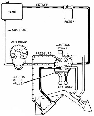
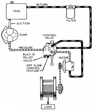
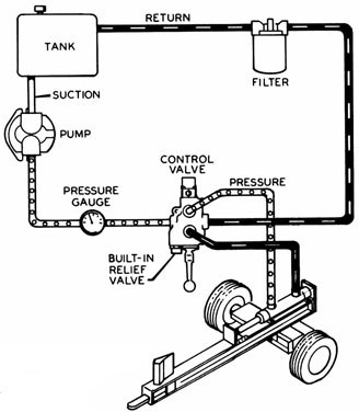
The cylinder is driven by hydraulic oil, under pressure, produced by a hydraulic pump. An engine, or electric motor, drives the pump shaft, and supplies the power for the system. The oil from the pump runs to a hydraulic valve, which provides control over the movement of the cylinder.
The oil source is a hydraulic reservoir (tank) which is connected directly to the inlet port of the pump. Most use AW32 viscosity (approx 10 wt.) hydraulic oil, which is of course an important part of any hydraulic system. There is a vented filler cap on the reservoir which allows air to “breathe” in and out. A simple air filter in it keeps dirt out.
A hydraulic relief valve controls the maximum pressure which can be created by the pump, and is a safety valve. It is usually located within the housing of the directional control valve. It is rarely in the pump. Without a relief, most hydraulic pumps will build pressure until something breaks, like a hose, or the cylinder, or the pump itself.
Most log splitters use a 2-stage gear pump which is a special type of hydraulic pump. They are rarely used in any other hydraulic systems. But they are widely available and relatively cheap because so many are sold for logsplitters.
Let’s start with the basics. Gear pumps are the most common, and least expensive type of hydraulic pump. They consist of 2 shafts, each with a gear which meshes with its twin to drive oil from the inlet port to the outlet or pressure port. Oil is trapped in the cavities between the gear teeth and carried around the outside of the gear toward the outlet port. The meshed gear teeth in the center keep oil from returning to the inlet side. One shaft sticks out of the housing and is driven by the engine. The other shaft is hidden within the pump housing. The one gear drives the other.
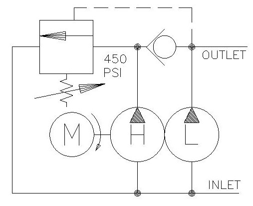
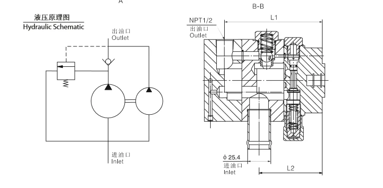
Two stage pumps give splitters great performance using small engines. A 2-stage pump consists of 2 gear pumps in a single housing, and a bypass valve. One gear set is about 3 times the size (length) of the second. When the valve is in neutral & system pressure is low, both gear sets are pumping oil into the system. With a “16 GPM” pump, they will pump 16 GPM when the pump shaft is rotated (by the engine) at 3400 RPM. That is, the combination of the outputs from both gear sets equals 16 GPM.
When the valve is shifted it moves the cylinder quite quickly. But when the log hits the wedge, the resistance increases, and pressure is backed up against the pump. Now the bypass valve comes into play. When the back pressure reaches 700 – 800 PSI, oil from the larger set of gears is allowed to pass back to the inlet side of the pump (at almost 0 PSI) rather than being forced out the pressure port. So the only oil being forced out is from the small gear set. This takes a lot less horsepower and allows the use of a reasonably small engine to develop the high pressure necessary to split wood, while giving the cylinder good speed when not under a heavy load (which is most of the time). The opening and closing of the bypass is automatic, activated by the oil pressure. It’s so smooth it’s usually difficult to notice it is happening. So 2-stage pumps give our log splitters the best of both: high pressure when we need it, and high speed the rest of the time.
We sometimes see home made log splitters with single stage pumps, often reused from another type of machine. They are usually quite slow unless a much bigger than normal engine is used.
The cylinder is the “actuator” of the system: it converts the hydraulic pressure and flow into force to split the wood, and speed to make it efficient. The larger the cylinder diameter the more force (tonnage) it puts out, but the slower it will go: it takes more oil to fill, and so takes longer.
The most common size for log splitters is “4 x 24″, 4″ bore by 24″ stroke. With 2500 PSI from the pump it can exert over 31,000 lbs of push force. To compare, a 5″ bore cylinder can produce 49,000 lbs force with the same pump, over 1 1/2 times as much. But the 5” cylinder will go 36% slower, which is why they are not common on ordinary splitters.
1. Pushed one way it shunts oil from the pump to the base port of the cylinder, causing it to extend. And it simultaneously allows oil from the rod-end port of the cylinder to flow into the return line.
2. When let go, the spool springs back to the neutral position; the oil from the pump is allowed straight through to the return port where it is recycled back to the tank, and the cylinder ports are blocked so the cylinder is stopped and held in position.
The relief valve consists of a heavy spring with a compression adjustment screw, and a ball or poppet against a seat. This is in a channel between the pressure inlet port and the return port, with the ball or poppet blocking the flow. If the oil pressure reaches the adjustment setting, perhaps 2500 PSI, it overcomes the spring pressure, the poppet backs off, and oil from the pump is allowed to bypass directly to the valve outlet, thus limiting the maximum oil pressure in the system. At normal working pressures, the relief remains closed and is not involved in the circuit.
The hydraulic oil for the system is stored in a tank, usually steel. Reservoirs serve two important functions: They allow the oil to settle any air bubbles and contamination particles; and they allow the oil to cool while it’s not circulating.
To provide sufficient cooling, the tank should be sized to hold at least one minute’s worth of oil. (16 gallons for a 16 GPM pump.) Oil which is too hot, 180F, will harden seals, and will be too thin to lubricate the spinning pump parts, causing early pump failure. We recommend 150F as the working maximum oil temperature.
The suction and return ports should be on the sides of the tank, a couple of inches above the bottom to avoid any sludge which may have settled there. The suction line should be low enough to never ingest any air, and the return should be low so as not to stir any air into the oil. Further, the 2 ports should be separated enough to avoid the hot returning oil from being immediately sucked back into the pump line.
Every good hydraulic system has a filter to remove fine contamination particles from the oil. The recommended rating is 10 microns, (10 microns equals 0.00039 inches; about 1/5 the diameter of a human hair). A filter this fine would plug the suction line, so it must be installed on the return, typically right at the tank return port.
Suction strainers in the tank are 100 micron or more, so can not catch the fine, damaging particles like the return filter. And if they get plugged they may starve the pump, greatly shortening its life. They are not recommended.
Hydraulic oil is blended with chemical additives beneficial for hydraulic systems. They help resist wear, shed contamination, maintain viscosity when cold, resist foaming, rust and oxidation, etc. Typical viscosity is around SAE 10, usually labelled AW32.
Hydraulic oil is not subjected to the burning temperatures of combustion engines, so it usually lasts a long time. The recommendation is to change oil if it is excessively dirty, or milky (water contamination) or smells bad or burned. If not, it’s better to just change the filter and save the cost of an oil change.
How to get more force? Either more pressure, or a larger cylinder. The pressure you probably can’t change much. Check the relief setting on your directional valve. It controls the maximum. We don’t suggest more than 2500 PSI, which is the practical maximum for most gear pumps. Yes they are sometimes rated at 3000 PSI or more. But that’s like driving your car 125 MPH. It may be able to do it, but all the time? Not such a good idea. Virtually all logsplitter pumps are rated for the same pressure. What’s the difference between pumps? Bigger gears, which produce more flow, which means more speed. And requires more horsepower to drive them. To get more force, you’ll need a larger bore cylinder. If you want the same speed as a smaller cylinder, you’ll need a larger pump, and probably a larger engine to drive it.
How to get more speed? Either more flow (GPM), or a smaller cylinder. The smaller cylinder won’t require more power, but will produce less force. More flow comes from a larger pump. So you’ll get the same force but will need to supply more horsepower to the new pump.
2. The highest rotation speed shall be limited within 1200r/min, while applying with water-based synthetic hydraulic fluids. The application of PV2R series double hydraulic vane pumps : Dongguan blince machinery and electronics co. 2. We are not only produce normal models, but also produce new models according to your design.

Push Button Stop/ Start, Lever Valve Action - Control lever forward: Pump into hose A, Returns to reservoir on hose B. Control lever neutral: Returns to reservoir on hose A and B. Control lever backward: Pump into hose B, Returns to reservoir on h


 8613371530291