
variable displacement hydraulic pump symbol manufacturer

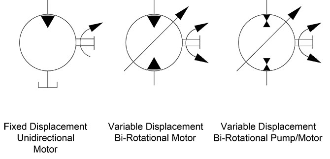
The base symbol for the hydraulic pump (Figure 1) is actually quite simple. It starts with the standard circle and a directional arrow pointing out one end from within that circle. The solid-filled triangle makes this a hydraulic pump while pneumatic pumps (and most pneumatic symbols) are outlines only. There exist no other options for this particular pump symbol, which can be accurately described as a fixed displacement, unidirectional hydraulic pump.
It’s rare to see a pump in any orientation but North when reading schematics, and they are often paired below to a line terminating into the reservoir symbol, which I show just once. If multiple components such as filters, ball valves, accessories or even other pumps are used, the tank line can be widened as needed. Other designers prefer to show every tank line terminate into the same small symbol, while others will place a tank symbol right at every component requiring it, just is done in electrics with the ground symbol.
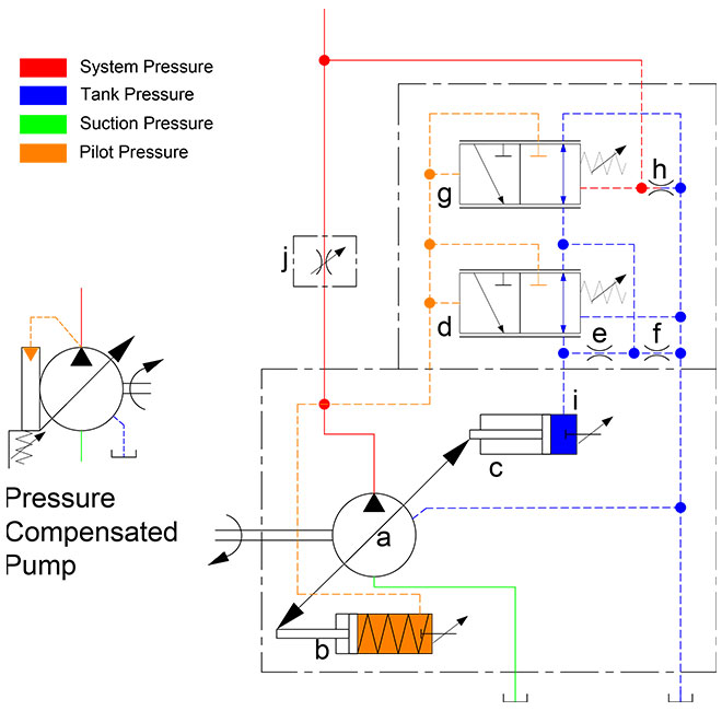
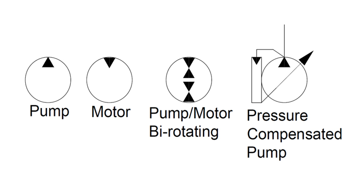
My favorite symbol to express the pressure compensated pump is the smaller of the two symbols in Figure 2. This is a slightly more detailed example of the symbol I depicted in Hydraulic Symbology 101, and I’ve added color to help with the explanation. Don’t worry about the scary looking object to the right, we’ll get to that shortly.
For this particular symbol of the pressure compensated pump, the shaft sticks out to the right, which can be attached to the square of a combustion engine prime mover symbol or the circular symbol of an electric motor. The semicircular arrow shows us the shaft rotates clockwise, or to the right since rotation direction is always observed from the vantage point of the shaft end.
The variable arrow bisects the pump symbol and of course tells us the pump is adjustable displacement. The method of displacement control is defined by the compound symbol attached to the pump’s left. Under the long rectangle is a spring with a variability arrow, which represents the pressure compensator spring, itself semienclosed and attached to the bottom of the pump’s variable arrow. Opposite the spring is a triangular input for pilot pressure, and this juxtaposition is intentional.
The orange pilot signal is taken directly from the red system pressure line exiting the pump, with the dashed orange line confirming it is indeed pilot energy. The spring setting fights with pilot pressure to infinitely and smoothly adjust the flow rate to match downstream pressure drop equal to the compensator setting. For example, if the setting is 3,000 psi, any downstream combination of load and flow-related pressure below 3,000 psi will see the spring maintain full displacement of the swashplate, producing full pump flow.
Moving along to the scary looking thing on the right, we have here the detailed breakdown of the variable displacement, pressure compensated, load-sensing, unidirectional hydraulic pump. You’ve likely seen this symbol before because the manufacturers prefer to show this level of detail, especially to differentiate advanced controls options like remoted compensation or horsepower control. This “load-sensing pump” will make sense to you shortly. I’ll warn that it will take some time and effort to understand this symbol as you methodically work through the rest of this article.
Starting with the pump (a), it has the diagonal variability arrow bisecting the circle and is attached to the rod ends of two cylinders. Cylinder (b) is the bias piston meant to force the pump to full displacement whenever possible, a task made easier by a spring pushing the piston forward. Some pumps make do with only a strong spring, but this example is balanced with pilot energy. Affixed on the right is a tiny object with a variable arrow, which can be adjusted to move left or right within the cylinder. Not all pumps have this additional component, which is the minimum volume stop, preventing the bias piston from retracting fully, which subsequently prevents fully standby of the pump.
If you’re familiar with cylinder symbols, you’ll see that (c) also looks like a single acting cylinder with a stroke adjustor at the cap side. This is the control piston, which will always be a larger bore diameter than the bias piston. The control piston’s stroke adjustment is called the maximum volume stop and is used to modify the maximum displacement of the pump, convenient when you need a displacement between the two sizes available for the chosen pump. The two “cylinders” are attached by their rods to each other, and as one extends the other must retract and vice versa, and I’ll explain shortly why and how their battle develops.
Because all load sensing pumps must be pressure compensated, I’ll start with (d), which is the pressure compensator. Although it looks different, it is essentially a relief valve governing the control piston (c). It’s shown in its neutral condition, where it bleeds the chamber of the control piston (c) through orifice (e), orifice (f), and also through the other compensator (g) where it can choose any flow path directly to tank. Regardless of its flow path, pilot energy inside the control piston (c) is zero, so it loses the battle with the bias piston (b) and the pump is on full displacement pump at its highest rate.
The load sense compensator (g) looks much the same as the pressure compensator (d) and is similar in function except where it takes pilot energy and what it does with it afterward. As with the pressure compensator symbol (d), it is a 3-way, 2-position valve that is spring-offset with adjustable pressure settings for both. Each is supplemented with the parallel lines above and below both positional envelopes, and these lines tell us the valve is infinitely variable between the two positions.
The variable orifice at (j) could be any flow control, lever valve or proportional valve used to adjust flow (which creates backpressure when reduced) in the red system pressure line starting at the pump. You can see the node just after the pump outlet that combines system pressure with pilot lines supplying the bias piston and both compensators. Let’s first take the load sense compensator (g) out of the picture and describe the pressure compensator (d) and what occurs during operation.
When the pump fires up, and assuming all downstream directional valves are closed, the spring inside the bias piston (b) fully strokes the pump to max displacement. This immediately creates pressure in the work and pilot lines as fluid fills the plumbing with no exit strategy, and this rise in pressure at the pilot line at (d) forces the pressure compensator to shift to the right. The second pilot line attached to the top of compensator (d) allows pilot energy to enter through line (i) where it fills the control piston (c) rapidly. Because the control piston is larger bore than the bias piston, it wins the fight and moves the pump’s variable arrow to reduce displacement until the only flow is what is required to overcome leakage. The pump is on “standby.”
Now when a downstream directional valve is opened, a flow path is created that drops system pressure to below the setting of the (d) compensator, and it immediately succumbs to spring pressure and snaps back to near its neutral setting, opening the drain lines once again to tank. The orifices (e) and (f) dampen the motion of the compensator, preventing rapid oscillations, but the orifice also prevents pressure spikes into the pump’s case. They also ensure that pressure doesn’t decay from the control piston (c) when system pressure degrades rapidly for fractions of a second. Flow from the pump will be balanced by the opposing bias and control pistons to match downstream pressure drop at exactly the pressure compensator setting.
Finally, we look at the operation of the load sense compensator (g) shown on top. It also receives a pilot signal directly from the pump outlet, but you’ll see that it also gets a competing signal from the work line after the metering orifice. The pressure signal at (g) compares the combined effort of the spring value and the load-sense pilot signal just before (h). The setting of the pressure compensator (d) is much higher than the setting of the load sense compensator (g), which is set to create reasonable pressure drop across (j). If the (d) compensator is set to 3,000 psi, it’ll only see this pressure on standby or max load pressure, while the (g) compensator might be set to 300 psi, where it measures pressure drop across (j) valve.
Typically a load sense circuit will have multiple orifices in a load sense network all feeding back a pilot signal to the load sense compensator (g), where it picks the highest pressure signal and meters the pump’s flow to match that pressure differential and provides just enough flow to satisfy the desired flow rate at the desired work pressure plus the pressure of the load sense compensator’s spring value. For example, if load pressure is 1,000 psi, the pump will hold pressure at 1,300 psi, providing the extra 300 psi just to create flow across the metering valve (j).
This symbol shows you that no matter the initial feeling of complexity, breaking down any schematic thoughtfully reveals its purpose of design. I fell in love with hydraulics when I learned about the load sensing concept. That just using columns of fluid pressure to create an efficient supply and demand scenario to satisfy many downstream actuators with essentially the exact flow and pressure they need for the job, and little more, I found exhilarating.

Designed for power and speed, the Oilgear PVV open-loop axial-piston hydraulic pumps can handle large, heavy-duty systems. Manufactured with advanced engineering and computer-optimized, the PVV pump range delivers up to 450 Bar / 560 horespower which equates to four times the horsepower at less than half the cost of other manufacturers pumps.
With it"s compact design available in several displacements, the PVV pumps offer a large selection of readily interchangeable controls. With improved response controls and reduced noise levels, its rugged cylinder design enhances performance.
The patented, pressure lubricated swashblock design offers high performance for high-cycling operations. It also contributes to the pump’s ability to run on low-viscosity fluids, including high water content, fire-resistant and other special fluids.
Zeus Hydratech fully supports the Oilgear PVV pump product line and is the only valid source for OEM parts. All Oilgear repairs are machined and tested per our original factory specifications.
Designed for power and speed, the Oilgear PVV open-loop axial-piston hydraulic pumps can handle large, heavy-duty systems. Manufactured with advanced engineering and computer-optimized, the PVV pump range delivers up to 450 Bar / 560 horespower which equates to four times the horsepower at less than half the cost of other manufacturers pumps.
With it"s compact design available in several displacements (200-540cc/rev), the PVV pumps offer a large selection of readily interchangeable controls. With improved response controls and reduced noise levels, its rugged cylinder design enhances performance.
The patented, pressure lubricated swashblock design offers high performance for high-cycling operations. It also contributes to the pump’s ability to run on low-viscosity fluids, including high water content, fire-resistant and other special fluids.
Zeus Hydratech fully supports the PVV pump product line and is the only valid source for OEM parts. All Oilgear repairs are machined and tested per our original factory specifications.

The displacement of a pump is defined by the volume of fluid that the gears, vanes or pistons will pump in one rotation. If a pump has a capacity of 30 cm3, it should treat 30 ml of fluid in one rotation.
In axial piston variable pumps, the flow is proportional to the drive speed and the displacement. The flow can be steplessly changed by adjusting the swivel angle. Axial piston variable ...
... axial piston pump type V60N is designed for open circuits in mobile hydraulics and operate according to the swash plate principle. They are available with the option of a thru-shaft for operating additional ...
Variable displacement axial piston pumps operate according to the bent axis principle. They adjust the geometric output volume from maximum to zero. As a result they vary the flow rate ...
... piston pump type V30D is designed for open circuits in industrial hydraulics and operate according to the swash plate principle. They are available with the option of a thru-shaft for operating additional ...
... circuit axial piston pumps are used as hydrostatic transmission components in self-propelled machines and for rotary drives in both fixed and mobile equipment of all kinds.
Axial piston twin flow pump. With a very high performance in all job conditions. Due to its twin flow configuration this pump allows a great variety of solutions in different job applications.
Air hydraulic pump, double pneumatic motor, double effect, foot operated with lock-up function, lever distributor valve (4/3), 10L tank, oil flow 8.5 / 0.26 l / min
... customer system options for mechanical, hydraulic and electric input solutions are available. Further special regulating features like torque control and pressure cut-off are also available. The reliable ...
... needs of truck hydraulics, the TXV variable displacement pumps with LS (Load Sensing) control allow flow regulation to suit the application requirements. The pump ...
... rev. displacements, these pumps are designed to operate in both directions of rotation (clockwise or counter-clockwise). Only one reference regardless of direction of rotation. The TXV indexable pumps ...
... PVG is a variable-displacement axial-piston pump designed to take on your most demanding applications. It offers high-pressure, superior performance in a compact design ...
Variable displacement pumps in closed loop; 3 basic design units and 8 max. displacement sizes of 14, 18, 21, 28, 35, 46, 56, 64 cc/rev; various control options; max. ...
Parker P2/P3 High Pressure Axial Piston Pumps are variable displacement, swashplate piston pumps designed for operation in open circuit, mobile hydraulic ...
... Series pump offers variable displacement axial piston pumps for open-circuit applications. Featuring a compact footprint and continuous operating pressure ...

BI pumps are axial piston pumps with single and double fixed displacement. They are available from 25 to 172 cm3/rot. and with a maximum pressure of 400bar. They can be assembled directly into the PTO´s, with the exception of the PTO’s of two shafts without support.

Manufacturer of standard and custom metering equipment and systems. Products include precision meter mix systems, metered dispensing systems, meter mix dispensing systems, precision gear metering pumps, prototype test systems and pump skid systems. Precision gear metering pumps such as extrusion/discharge metering pumps, hazardous/toxic materials metering pumps, high/low viscosity metering pumps, high pressure metering pumps, multiple streams metering pumps, spraying/coating metering pumps, dosing pumps, drum metering pumps, submersible metering pumps and platen based drum metering pumps are available. Capabilities include repairing, rebuilding, upgrading and preventive maintenance. Consulting and on-site training services are available. Markets served include aerospace, aviation, packaging, building and construction, medical, pharmaceutical, electronics, textiles, personal care products and food manufacturing industries.

ISO 9001:2000 certified custom manufacturer of variable displacement axial piston pumps. Specifications of pumps include 3600 rpm maximum speed & 350 psi maximum pressure. Optional electronic control units provide proportional control, automotive control, control with feed-back for speed, displacement & steering angle, power limiter & customized software. Also available are hydraulic, mechanical & electric servo controls. Optional pump features include front & rear lever bypass, electrical bypass with brake release, reinforced roller bearings, suction filter, SAE flanges, UNF threads, cut-off pressure valve, pressure inlet & purge valve. Other products include gearboxes, drivelines, axles, electric wheel drives, hydraulic motors & pumps.

The top symbol shows a fixed displacement hydraulic pump that rotates in an anticlockwise direction (shown by the arrow) when viewed onto the drive flange and drive-shaft. The black triangle shows it is a hydraulic pump and which direction the flow will go in.
The middle symbol has an arrow through it indicating a variable displacement pump. It also shows a case drain line coming from the side of the pump casing. Generally, it is only fixed displacement pumps that can work without a case drain line.
The industrial hydraulic symbol or just the hydraulic symbol is the first step towards an understanding of the hydraulic system. Without a basic understanding of symbols, one cannot efficiently troubleshoot the hydraulic system completely. A hydraulic system consists of cylinders, motors, valves, and pumps connected via hydraulic hoses and pipes. Due to the complexity of showing these components in a diagram we use symbols instead of absolute components.
Most hydraulic industries follow standard DIN ISO 1219 for the design of hydraulic circuits, however, one can find differences in individual drawings with the company.
Answer: The symbol will be the same for all pumps. Concrete pumps are designed differently because it has to handle dense liquid or semi-solid materials, but the symbol will be similar.See the Symbol

Another option is to utilize a load sense compensator. With a load sense compensator, this compensator will include a lighter spring setting to control the swash plate. Upstream pressure is ported into a load sense port on the pump, as the pressure requirement increases, the pressure acts against the load sense piston. Once the pressure requirement is higher than the offset, the pump swash plate angle changes and the pump begins to increase flow, by increasing the swash plate angle, until we have enough pressure to balance the piston. Once balanced, the flow remains steady until the load changes.
The offset pressure is normally 200-300 PSI. With a load sense compensator, the pump produces what the load requires plus the spring offset, normally 200-300 PSI.
With a standard pressure compensator, you would have to set the pump at 2600 PSI to accomplish the work. When the work only requires 1500 PSI, the pump will be trying to produce 2600 PSI. Fifty percent of the time, your system will be operating at 1100 PSI of inefficiency, which means heat. With a load sense compensator, when the load requires 1500 PSI, the pump will actually produce about 17-1800 PSI. Yes, this is 300 PSI inefficient, but that is much better than 1100 PSI inefficient.
With a varying load, the load sense is a much better system. For additional control, you can utilize an electronic proportional flow control or throttle. You can use an electrical signal to vary the hydraulic signal which is received by the pump’s load sense line. This would give you full electronic control of the amount of flow the pump produces.
There are additional control options which allow you to remotely control the pressure compensator. With this remote compensator control, you can set 2 or more different system pressures. With the ability of a variable piston pump to build 5,000 or more PSI; the additional setting can be used when operating components with a much lower pressure requirement.
The next control is a torque limiting or HP limiting control. By adding an additional spring and piston, you can set a pump to always maximize its allowable input torque, therefore, maximizing output flow and pressure at a defined setting.
Our pump has an output of 15 CIR, a maximum flow of about 113 gallons at 1750 RPM. Our prime mover is an electric motor, 75HP with a 1.15 service factor. I want to keep my cylinder moving as fast as possible, but I also want to ensure that I never exceed a power demand 82 HP.
At 82 HP, the pump can produce 1254 PSI at full output, 113 GPM. As the load requires more pressure, the pump will begin to reduce flow and increase pressure. At 90 GPM flow, the system will produce about 1560 PSI; at 60 GPM we can get almost 2350 PSI. At 4500 PSI, the pump flow will be reduced to about 31 GPM. The advantage of this pump is that the internal controls of the pump are adjusting to maximize flow and pressure at all times without exceeding the available HP.
If I wanted to use a pump which could produce 113 gallons of flow at 4500 PSI, I would need 296 HP. If I choose a 75 HP motor with a pressure compensated variable piston pump, the motor would stall before the pressure compensator could kick in and reduce the pump flow. Depending on the load, a load sense pump could also stall the 75 HP motor if the load pressure is high enough to use up the HP before the pressure compensator kicks in. With a torque limiting (HP) control, we utilize the full limits of the prime mover and maximize power usage.
Pumps do not make pressure, pumps make flow and the restriction of the flow is where the pressure is created.After the unit is deadheaded, start by bringing the relief and compensator up together. You should be able to tell by the sound when the pump is on stroke and when it is compensated.
Back the compensator out (CCW) until you hear the pump come on stroke (it gets loud) and then turn the adjustment back in (CW) until pump compensation is achieved and the pump is quiet again.
Tighten the lock nut on the relief and compensator to assure they will not change after setup. If you are in a noisy environment and can’t hear the pump come on stroke or the relief valve open, you can set the pump compensator and relief valve by watching the amp draw on one leg of the electrical service. You can tell by the amp draw on the motor when the relief cracks or when the pump compensates.

In an axial-piston pump, the pistons and cylinder rotate around the center, longitudinal axis. The pistons and shoes move in and out of the cylinder because they are sliding upon a stationary, variable angle, swashblock.

Variable Displacement Piston Pumps – A Series – Yuken offers low noise/high efficiency, swash plate type variable piston pumps, these have been developed by Yuken’s leading hydraulic engineers and provide a diverse lineup to meet a wide range of application requirements. Variable Displacement Piston Pumps – A Series.For other products visit Products
Yuken: Hydraulic specialist and its products are recognised as an industry leading brand, utilised in various regular and specialist applications around the world.
We supply standard, off-the-shelf products but at Yuken, we will always go the extra mile to understand your needs and provide Hydraulic solutions,which will allow you to meet the increasingly tough challenges that we all face.
Our company dates back to 1929 in Japan and in 1980 Yuken Europe Ltd. was founded. During this time Yuken: Hydraulic specialist has accumulated a wealth of practical and technical expertise and our enduring success lies in the fact that our history is filled with examples of how we have met and exceeded the needs of machine and system builders.
Our Hydraulic products are used by original equipment manufacturers operating in a diverse variety of sectors including shipping, construction, subsea operations, chocolate-makers and contact lens manufacturing equipment.
The demanding requirements of those machine, system builders and hydraulic power pack, who need improved productivity, and performance to gain technical edges over their competition, means that we have built ourselves a reputation for quality and cutting edge innovation and design, developing a range of products which will enhance any system they are used in.


 8613371530291