
variable flow hydraulic pump factory
The displacement of a pump is defined by the volume of fluid that the gears, vanes or pistons will pump in one rotation. If a pump has a capacity of 30 cm3, it should treat 30 ml of fluid in one rotation.
In axial piston variable pumps, the flow is proportional to the drive speed and the displacement. The flow can be steplessly changed by adjusting the swivel angle. Axial piston variable ...
... axial piston pump type V60N is designed for open circuits in mobile hydraulics and operate according to the swash plate principle. They are available with the option of a thru-shaft for operating additional ...
Variable displacement axial piston pumps operate according to the bent axis principle. They adjust the geometric output volume from maximum to zero. As a result they vary the flow rate ...
... piston pump type V30D is designed for open circuits in industrial hydraulics and operate according to the swash plate principle. They are available with the option of a thru-shaft for operating additional ...
... circuit axial piston pumps are used as hydrostatic transmission components in self-propelled machines and for rotary drives in both fixed and mobile equipment of all kinds.
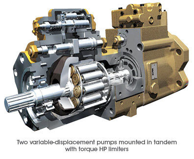
Axial piston twin flow pump. With a very high performance in all job conditions. Due to its twin flow configuration this pump allows a great variety of solutions in different job applications.
Air hydraulic pump, double pneumatic motor, double effect, foot operated with lock-up function, lever distributor valve (4/3), 10L tank, oil flow 8.5 / 0.26 l / min
... customer system options for mechanical, hydraulic and electric input solutions are available. Further special regulating features like torque control and pressure cut-off are also available. The reliable ...
... needs of truck hydraulics, the TXV variable displacement pumps with LS (Load Sensing) control allow flow regulation to suit the application requirements. The pump ...
... rev. displacements, these pumps are designed to operate in both directions of rotation (clockwise or counter-clockwise). Only one reference regardless of direction of rotation. The TXV indexable pumps ...
... PVG is a variable-displacement axial-piston pump designed to take on your most demanding applications. It offers high-pressure, superior performance in a compact design ...
Variable displacement pumps in closed loop; 3 basic design units and 8 max. displacement sizes of 14, 18, 21, 28, 35, 46, 56, 64 cc/rev; various control options; max. ...
Parker P2/P3 High Pressure Axial Piston Pumps are variable displacement, swashplate piston pumps designed for operation in open circuit, mobile hydraulic ...
... Series pump offers variable displacement axial piston pumps for open-circuit applications. Featuring a compact footprint and continuous operating pressure ...
... noise level. The pump delivery flow is dependent on the present drive speed and geometric displacement. The flow is adjustable in a range between 0 and Qmax.
Designed for power and speed, the Oilgear PVV open-loop axial-piston hydraulic pumps can handle large, heavy-duty systems. Manufactured with advanced engineering and computer-optimized, the PVV pump range delivers up to 450 Bar / 560 horespower which equates to four times the horsepower at less than half the cost of other manufacturers pumps.
With it"s compact design available in several displacements, the PVV pumps offer a large selection of readily interchangeable controls. With improved response controls and reduced noise levels, its rugged cylinder design enhances performance.
The patented, pressure lubricated swashblock design offers high performance for high-cycling operations. It also contributes to the pump’s ability to run on low-viscosity fluids, including high water content, fire-resistant and other special fluids.
Zeus Hydratech fully supports the Oilgear PVV pump product line and is the only valid source for OEM parts. All Oilgear repairs are machined and tested per our original factory specifications.
In a variable flow hydraulic piston pump, the outlet flow is proportional to the rotational speed of the shaft and the displacement volume of the variable and is variable in the form of flow. The output current can be adjusted from zero to the maximum value with the angle of the angle bar. Depending on the type of controller that each of the piston pumps has a variable flow, the flow changes are uniform and the flow is continuous.

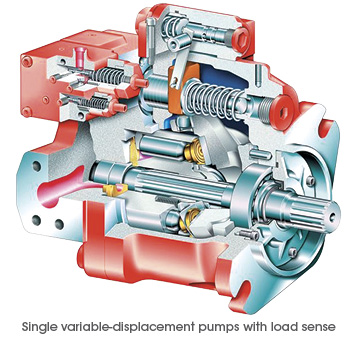
Another option is to utilize a load sense compensator. With a load sense compensator, this compensator will include a lighter spring setting to control the swash plate. Upstream pressure is ported into a load sense port on the pump, as the pressure requirement increases, the pressure acts against the load sense piston. Once the pressure requirement is higher than the offset, the pump swash plate angle changes and the pump begins to increase flow, by increasing the swash plate angle, until we have enough pressure to balance the piston. Once balanced, the flow remains steady until the load changes.
The offset pressure is normally 200-300 PSI. With a load sense compensator, the pump produces what the load requires plus the spring offset, normally 200-300 PSI.
With a standard pressure compensator, you would have to set the pump at 2600 PSI to accomplish the work. When the work only requires 1500 PSI, the pump will be trying to produce 2600 PSI. Fifty percent of the time, your system will be operating at 1100 PSI of inefficiency, which means heat. With a load sense compensator, when the load requires 1500 PSI, the pump will actually produce about 17-1800 PSI. Yes, this is 300 PSI inefficient, but that is much better than 1100 PSI inefficient.
With a varying load, the load sense is a much better system. For additional control, you can utilize an electronic proportional flow control or throttle. You can use an electrical signal to vary the hydraulic signal which is received by the pump’s load sense line. This would give you full electronic control of the amount of flow the pump produces.
There are additional control options which allow you to remotely control the pressure compensator. With this remote compensator control, you can set 2 or more different system pressures. With the ability of a variable piston pump to build 5,000 or more PSI; the additional setting can be used when operating components with a much lower pressure requirement.
The next control is a torque limiting or HP limiting control. By adding an additional spring and piston, you can set a pump to always maximize its allowable input torque, therefore, maximizing output flow and pressure at a defined setting.
Our pump has an output of 15 CIR, a maximum flow of about 113 gallons at 1750 RPM. Our prime mover is an electric motor, 75HP with a 1.15 service factor. I want to keep my cylinder moving as fast as possible, but I also want to ensure that I never exceed a power demand 82 HP.
At 82 HP, the pump can produce 1254 PSI at full output, 113 GPM. As the load requires more pressure, the pump will begin to reduce flow and increase pressure. At 90 GPM flow, the system will produce about 1560 PSI; at 60 GPM we can get almost 2350 PSI. At 4500 PSI, the pump flow will be reduced to about 31 GPM. The advantage of this pump is that the internal controls of the pump are adjusting to maximize flow and pressure at all times without exceeding the available HP.
If I wanted to use a pump which could produce 113 gallons of flow at 4500 PSI, I would need 296 HP. If I choose a 75 HP motor with a pressure compensated variable piston pump, the motor would stall before the pressure compensator could kick in and reduce the pump flow. Depending on the load, a load sense pump could also stall the 75 HP motor if the load pressure is high enough to use up the HP before the pressure compensator kicks in. With a torque limiting (HP) control, we utilize the full limits of the prime mover and maximize power usage.
Variable displacement axial piston pumps adjust the geometric output volume from maximum to zero. As a result they vary the flow rate that is provided to the consumers.

Variable-displacement pumps are used in hydraulic systems where the flow requirements vary. This usually means the system has several actuators and, depending on the current cycle of the machine, the number of actuators moving at a given time will fluctuate. The most common type of variable-displacement pump is the pressure-compensating pump.
Pressure-compensating pumps are designed to deliver only the amount of flow required by the system to maximize efficiency and avoid heat generation. The compensator is adjusted to a pressure somewhat higher than that required to move the system’s heaviest load.
A pressure-compensating pump will deliver its maximum flow until the system pressure reaches the compensator setting. Once the compensator setting is reached, the pump will be de-stroked to deliver only the amount of flow that will maintain the compensator setting in the line.
Whenever more flow is demanded by the system (such as would occur when an additional actuator begins to move), the pump will increase its stroke to meet the new flow demand. Whenever the system flow needs to decrease (such as when one or more actuators are stopped), the pump stroke is reduced.
When the system is stopped completely, the pump stroke is reduced almost to zero. It will stroke only a very small amount or whatever is required to maintain the compensator setting in the line, overcoming any system bypassing or leaks. While a pressure-compensating pump is efficient, the standby pressure remains high.
Adjusting a pressure-compensating pump is quite simple. With all flow blocked and the system idle, the compensator valve is adjusted to the desired pressure. However, some pressure-compensating pumps have two valves mounted on the pump body.
The two adjustments can look nearly identical. This type of pressure-compensating pump is called a load-sensing pump. The second adjustment is called either a “load-sensing” valve or “flow-compensator” valve.
A load-sensing pump is designed to reduce its pressure to a much lower standby level whenever the system is idle. This can conserve energy and reduce heat and wear in systems that spend a significant amount of time in an idle condition.
Whenever the system is moving a load, the high-pressure adjustment limits the system pressure. For instance, as a cylinder is extended, pressure in the system will build as necessary to move the load. Eventually, the cylinder reaches the end of its stroke, and flow is blocked.
When the flow is blocked in this fashion, the system pressure can build no higher than the setting of the compensator, but until another load is to be moved, there is no need for the system pressure to be kept so high.
Most load-sensing systems have a pump-loading directional-control valve of some sort that can place the system in an idle condition until it is necessary to move another load. When the pump-loading valve is shifted, the system pressure drops to the much lower load-sensing valve setting.
A load-sensing valve usually is smaller than the compensator valve and typically mounted directly on top of the compensator. The compensator valve is closer to the pump. The load-sensing valve is factory preset and normally does not need to be adjusted during the initial pump setup. In most pumps, the factory preset is approximately 200-300 pounds per square inch (psi).
The most common reason to adjust a load-sensing valve is because someone unfamiliar with the pump has mistakenly attempted to set the maximum system pressure by adjusting the load-sensing valve instead of the compensator. This not only can result in unstable system pressure but in some cases can also void any warranty on the pump.
A typical configuration of a pressure-compensating pump is shown in Figure 1. A pump-loading valve is used to determine whether the system is idle or prepared to move a load. The pump-loading valve is de-energized whenever the system is idle.
Pilot pressure on the left-hand side of the load-sensing valve is then released to the tank. The pilot line on the right-hand side of the load-sensing valve is connected to the pressure line at the pump outlet. System pressure shifts the load-sensing valve and directs pressure to reduce the pump stroke so that system pressure drops to the load-sensing setting of 300 psi, as illustrated in Figure 2.
When a load is to be moved, the pump-loading valve is energized. This directs pilot pressure to the left side of the load-sensing valve, keeping it from shifting. System pressure shifts the compensator valve to de-stroke the pump exactly the amount necessary to limit system pressure to the compensator setting, 3,000 psi as shown in Figure 3.
To make the pressure settings, always adjust the load-sensing valve first. The pump should be deadheaded by closing the manual hand valve. With the pump-loading valve de-energized, pressure will build only to the current setting of the load-sensing valve. Adjust the load-sensing valve to the desired pressure.
Once the load-sensing valve is set, energize the pump-loading valve. System pressure will then build to the current compensator setting. Adjust the compensator to the desired setting. Open the manual valve, and the system can be placed back into service.
Jack Weeks is a hydraulic instructor and consultant for GPM Hydraulic Consulting. Since 1997 he has trained thousands of electricians and mechanics in hydraulic troubleshooting methods. Jack has...
There are typically three types of hydraulic pump constructions found in mobile hydraulic applications. These include gear, piston, and vane; however, there are also clutch pumps, dump pumps, and pumps for refuse vehicles such as dry valve pumps and Muncie Power Products’ Live PakTM.
The hydraulic pump is the component of the hydraulic system that takes mechanical energy and converts it into fluid energy in the form of oil flow. This mechanical energy is taken from what is called the prime mover (a turning force) such as the power take-off or directly from the truck engine.
With each hydraulic pump, the pump will be of either a uni-rotational or bi-rotational design. As its name implies, a uni-rotational pump is designed to operate in one direction of shaft rotation. On the other hand, a bi-rotational pump has the ability to operate in either direction.
For truck-mounted hydraulic systems, the most common design in use is the gear pump. This design is characterized as having fewer moving parts, being easy to service, more tolerant of contamination than other designs and relatively inexpensive. Gear pumps are fixed displacement, also called positive displacement, pumps. This means the same volume of flow is produced with each rotation of the pump’s shaft. Gear pumps are rated in terms of the pump’s maximum pressure rating, cubic inch displacement and maximum input speed limitation.
Generally, gear pumps are used in open center hydraulic systems. Gear pumps trap oil in the areas between the teeth of the pump’s two gears and the body of the pump, transport it around the circumference of the gear cavity and then force it through the outlet port as the gears mesh. Behind the brass alloy thrust plates, or wear plates, a small amount of pressurized oil pushes the plates tightly against the gear ends to improve pump efficiency.
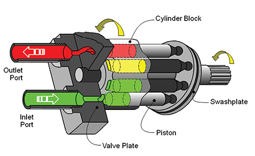
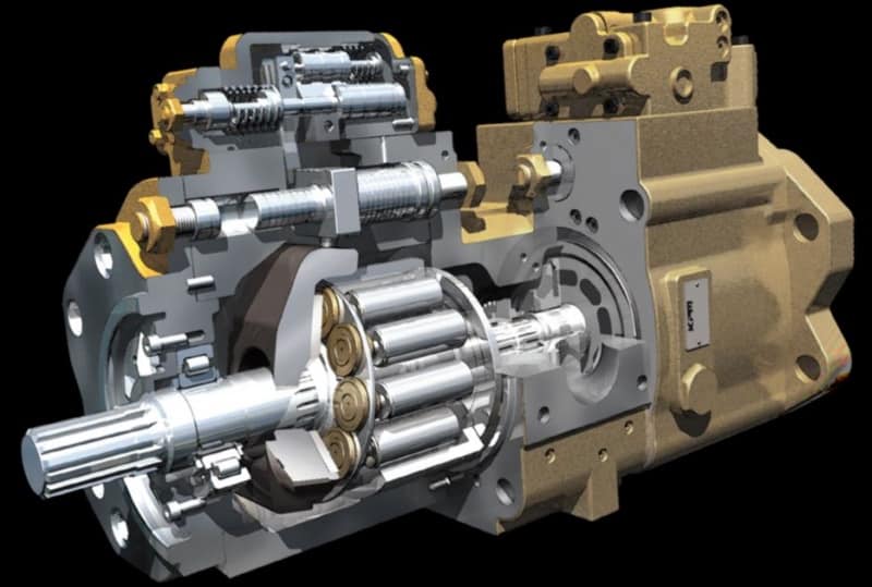
A cylinder block containing pistons that move in and out is housed within a piston pump. It’s the movement of these pistons that draw oil from the supply port and then force it through the outlet. The angle of the swash plate, which the slipper end of the piston rides against, determines the length of the piston’s stroke. While the swash plate remains stationary, the cylinder block, encompassing the pistons, rotates with the pump’s input shaft. The pump displacement is then determined by the total volume of the pump’s cylinders. Fixed and variable displacement designs are both available.
With a fixed displacement piston pump, the swash plate is nonadjustable. Its proportional output flow to input shaft speed is like that of a gear pump and like a gear pump, the fixed displacement piston pump is used within open center hydraulic systems.
As previously mentioned, piston pumps are also used within applications like snow and ice control where it may be desirable to vary system flow without varying engine speed. This is where the variable displacement piston pump comes into play – when the hydraulic flow requirements will vary based on operating conditions. Unlike the fixed displacement design, the swash plate is not fixed and its angle can be adjusted by a pressure signal from the directional valve via a compensator.
Flow and Pressure Compensated Combined – These systems with flow and pressure compensation combined are often called a load-sensing system, which is common for snow and ice control vehicles.
Vane pumps were, at one time, commonly used on utility vehicles such as aerial buckets and ladders. Today, the vane pump is not commonly found on these mobile (truck-mounted) hydraulic systems as gear pumps are more widely accepted and available.
Within a vane pump, as the input shaft rotates it causes oil to be picked up between the vanes of the pump which is then transported to the pump’s outlet side. This is similar to how gear pumps work, but there is one set of vanes – versus a pair of gears – on a rotating cartridge in the pump housing. As the area between the vanes decreases on the outlet side and increases on the inlet side of the pump, oil is drawn in through the supply port and expelled through the outlet as the vane cartridge rotates due to the change in area.
Input shaft rotates, causing oil to be picked up between the vanes of the pump which is then transported to pump outlet side as area between vanes decreases on outlet side and increases on inlet side to draw oil through supply port and expel though outlet as vane cartridge rotates
A clutch pump is a small displacement gear pump equipped with a belt-driven, electromagnetic clutch, much like that found on a car’s air conditioner compressor. It is engaged when the operator turns on a switch inside the truck cab. Clutch pumps are frequently used where a transmission power take-off aperture is not provided or is not easily accessible. Common applications include aerial bucket trucks, wreckers and hay spikes. As a general rule clutch pumps cannot be used where pump output flows are in excess of 15 GPM as the engine drive belt is subject to slipping under higher loads.
What separates this pump from the traditional gear pump is its built-in pressure relief assembly and an integral three-position, three-way directional control valve. The dump pump is unsuited for continuous-duty applications because of its narrow, internal paths and the subsequent likelihood of excessive heat generation.
Dump pumps are often direct mounted to the power take-off; however, it is vital that the direct-coupled pumps be rigidly supported with an installer-supplied bracket to the transmission case with the pump’s weight at 70 lbs. With a dump pump, either a two- or three-line installation must be selected (two-line and three-line refer to the number of hoses used to plumb the pump); however, a dump pump can easily be converted from a two- to three-line installation. This is accomplished by inserting an inexpensive sleeve into the pump’s inlet port and uncapping the return port.
Many dump bodies can function adequately with a two-line installation if not left operating too long in neutral. When left operating in neutral for too long however, the most common dump pump failure occurs due to high temperatures. To prevent this failure, a three-line installation can be selected – which also provides additional benefits.
Pumps for refuse equipment include both dry valve and Live Pak pumps. Both conserve fuel while in the OFF mode, but have the ability to provide full flow when work is required. While both have designs based on that of standard gear pumps, the dry valve and Like Pak pumps incorporate additional, special valving.
Primarily used on refuse equipment, dry valve pumps are large displacement, front crankshaft-driven pumps. The dry valve pump encompasses a plunger-type valve in the pump inlet port. This special plunger-type valve restricts flow in the OFF mode and allows full flow in the ON mode. As a result, the horsepower draw is lowered, which saves fuel when the hydraulic system is not in use.
In the closed position, the dry valve allows just enough oil to pass through to maintain lubrication of the pump. This oil is then returned to the reservoir through a bleed valve and small return line. A bleed valve that is fully functioning is critical to the life of this type of pump, as pump failure induced by cavitation will result if the bleed valve becomes clogged by contaminates. Muncie Power Products also offer a butterfly-style dry valve, which eliminates the bleed valve requirement and allows for improved system efficiency.
It’s important to note that with the dry valve, wear plates and shaft seals differ from standard gear pumps. Trying to fit a standard gear pump to a dry valve likely will result in premature pump failure.
Encompasses plunger-type valve in the pump inlet port restricting flow in OFF mode, but allows full flow in ON mode lowering horsepower draw to save fuel when not in use
Wear plates and shaft seals differ from standard gear pumps – trying to fit standard gear pump to dry valve likely will result in premature pump failure
Live Pak pumps are also primarily used on refuse equipment and are engine crankshaft driven; however, the inlet on a Live Pak pump is not outfitted with a shut-off valve. With a Live Pak pump, the outlet incorporates a flow limiting valve. This is called a Live Pak valve. The valve acts as an unloading valve in OFF mode and a flow limiting valve in the ON mode. As a result, the hydraulic system speed is limited to keep within safe operating parameters.
Outlet incorporates flow limiting valve called Live Pak valve – acts as an unloading valve in OFF mode and flow limiting valve in ON mode restricting hydraulic system speed to keep within safe operating parameters

A pressure compensator is a device built into some pumps for the purpose of automatically reducing (or stopping) pump flow if system pressure sensed on the pump outlet port, should rise above a pre-set desired maximum pressure (sometimes called the "firing" pressure). The compensator prevents the pump from being overloaded if an overload is placed on the hydraulic system.
A compensator is built into the pump at the factory and usually cannot be added in the field. Any pump built with variable displacement can be controlled with a compensator. These include several types of axial piston pumps and unbalanced (single lobe) vane pumps. Radial piston pumps can sometimes be built with variable displacement but do not lend themselves readily to this action. Most other positive displacement pumps including internal and external gear, balanced (double lobe) vane, gerotor, and screw types cannot be built with variable displacement.
Figure 1 is a schematic of a check valve axial piston pump, variable displacement, controlled with a pressure compensator. The pistons, usually 5, 7, or 9 in number, are stroking inside a piston block which is keyed to and is rotating with the shaft. The left ends of the pistons are attached through swivel joints, to piston shoes which bear against and slide around on the swash plate as the piston block rotates. The swash plate itself does not rotate; it is mounted on a pair of trunnions so it can swivel from neutral (vertical) position to a maximum tilt angle. The angle which the swash plate makes to the vertical causes the pistons to stroke, the length of stroke being proportional to the angle. Normally, at low system pressures, the swash plate remains at its maximum angle, held there by spring force, hydraulic pressure, or by the dynamics of pump construction, and pump flow remains at maximum. The compensator acts by hydraulic pressure obtained internally from the pump outlet port. When pump pressure rises high enough to over-come the adjustable spring behind the compensator piston, the "firing" pressure has been reached, and the compensator piston starts to pull the swash plate back toward neutral, reducing pump displacement and output flow. The spring in the compensator can be adjusted for the desired maximum or "firing" pressure.
Under working conditions, on a moderate system overload, the compensator piston reduces the swash plate angle just enough to prevent the system pressure from exceeding the "firing" pressure adjusted on the compensator. On severe overloads the compensator may swing the swash plate back to neutral (vertical) to reduce pump flow to zero.
Maximum Displacement Stops. Some pumps are available with internal stops to limit the tilt angle of the swash plate. These stops limit the maximum flow and limit the HP consumption of the pump. They may be fixed stops, factory installed and inaccessible from the outside, or they may be externally adjustable with a wrench.
Manual Control Lever. Some pressure compensated pumps, especially hydrostatic transmission pumps, are provided with an external control lever to enable the operator to vary the swash plate angle (and flow) from zero to maximum. On these pumps the pressure compensator is arranged to override the manual lever and to automatically reduce the swash plate angle if a system overload should occur even though the operator control lever is still shifted to maximum displacement position.
Basically the pressure compensator is designed to unload the pump when system pressure reaches the maximum design pressure. When the pump is unloaded in this way, there is little HP consumed and little heat generated even though pressure remains at the maximum level, because there is no flow from the pump.
Variable displacement pumps are usually more expensive than fixed displacement types, but are especially useful in systems where several branch circuits are to be supplied from one pump, and where full pressure may be required simultaneously in more than one branch, and where the pump must be unloaded when none of the branches is ill operation. If individual 4-way valves are used in each branch, each valve must have a closed center spool. The inlet ports on all 4-way valves must be connected in parallel across the pump line. However, if all branch circuits are operated from a bank valve of the parallel type, a pressure compensated variable displacement pump may not be necessary; a fixed displacement pump, gear, vane, or piston, may serve equally well because the bank valve will unload the pump when all valve handles are placed in neutral, but when two or more handles are simultaneously shifted, their branch circuits will automatically be placed in a parallel connection.
As in all hydraulic systems, more pump oil will flow to the branch with the lightest load. Bank valve handles can be modulated to equalize the flow to each branch. When individual 4-way valves are used in each branch, flow control valves may be installed in the branch circuits and adjusted to give the flow desired in each branch.
Figure 2 shows a multiple branch circuit in which a variable displacement pump is used to advantage. Individual 4-way valves, solenoid operated, are used for each branch, and they have closed center porting. Please refer to Design Data Sheet 54 for possible drift problems on a pressure manifold system. A pressure relief valve is usually required even with a pressure compensated pump due to the time interval required for the swash plate to reduce its tilt angle when a sudden overload occurs. The relief valve will help absorb part of the pressure spike generated during this brief interval. It should be adjusted to crack at about 500 PSI higher than the pressure adjustment of the compensator piston spring to prevent oil discharge across it during normal operation.
All hydrostatic transmission systems use a variable displacement pump with pressure compensator, and often combine the compensator with other controls such as the horsepower input limiter, load sensing, flow sensing, or constant flow control.


 8613371530291