
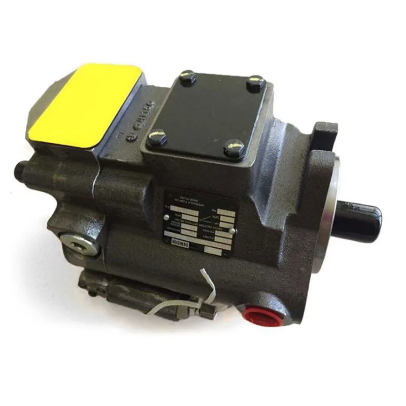
variable pressure hydraulic pump in stock

This variable pump has an adjustable pressure setting. Once the pressure setting is reached the pump outflow is de-stroked to zero. This helps reduce hydraulic heat generation and power consumption. It also comes with a maximum flow limiter adjustment to fine tune the maximum speed of the actuators in the system.

... Our hydraulic pumps are designed for safe operation in explosion prone area. The electric driven pumps are protected against rain, splash water and dust deposit (protection ...
The Power Team 120 series pump is exactingly designed for heavy duty, extended cycle operation up to 400 Ton. Built in grit, the series 120 pump can start and operate under full load, even with voltage ...
... continuous pressure (demand) pump contains all the necessary controls and circuitry for powering single- or double-acting continuous pressure workholding systems. It has a pressure switch and pressure regulator, both ...
The Power Team 120 series pump is exactingly designed for heavy duty, extended cycle operation up to 400 Ton. Built in grit, the series 120 pump can start and operate under full load, even with voltage ...
Like all the pumps of the HP Series, it is suitable for any hydraulic application which require very high hydraulic output pressures and a moderate and controllable oil flow, to ensure ...
The HP-AP pump, like all HP Series pumps, can be installed in any hydraulic applications which requires high working pressures and moderate and controllable oil flow. Our HP Series air-hydraulic ...
The HP-RC pump, like all the HP Series pumps, can be installed in any hydraulic applications which requires high working pressures and moderate and controllable oil flow. Our HP Series ...
... variable displacement pump DPVD impresses with its innovative technology. Thanks to the inverse piston, the pump manages large swing angles and can be used with nominal pressures up to 400 bar. The model ...
... transmission, the C Pump has a reputation for long, dependable service. The Oilgear C Type pump is a constant-delivery, one-way, radial rolling piston pump. Renowned for its tremendous ...
... noise level. The pump delivery flow is dependent on the present drive speed and geometric displacement. The flow is adjustable in a range between 0 and Qmax.
... piston variable displacement pumps, Series 20, are of swash plate design with variable flow capability suitable for hydrostatic transmissions with closed circuit. The flow rate is in proportional relation with the input ...
... this anti-clockwise pump in stock as standard. However, it can be delivered within 2 days. Please contact our product specialist to order this item.

Boasting high pressure, low noise and energy saving technology in a compact package,the Nachi PZH is a variable-displacement axial-piston pump, designed to take on all demanding applications.
The PZH manages to save energy and reduce operating noise by utilising low friction engineering on all sliding surfaces. Pressure pulsation is also reduced, therefore providing a smoother pressure flow within the hydraulic circuit (which is incredibly important in any extrusion/forming process to reduce ripple in the finished manufactured part.)
For customers looking to specify a high performance a reliable 70cc/rev pressure compensated, axial piston pump capable of 350 bar, the PZH-3B makes a first-class substitute to the following pump models in the same pressure and flow class:
Zeus Hydratech fully supports the Nachi PZHpump product line and is the only valid source for OEM parts in the South of the UK. All Nachi repairs are machined and tested per our original factory specifications.

Continental Hydraulics are at the forefront of engineering hydraulic solutions for over 50 years-a testament to a long-standing reputation built upon your challenges and opportunities. A worldwide leader- a one-stop-shop for valves, pumps, power units and proportional products-all assembled in the USA.
Continental Hydraulics PowrFlow™ PVR Vane Pumps deliver the rugged, reliable performance and value you’ve come to expect in all our products. They outperform sensitive piston pumps in harsh environments. PVR Vane Pumps deliver faster response, and require less external compensation compared to fixed displacement designs.

Check that the pump shaft is rotating. Even though coupling guards and C-face mounts can make this difficult to confirm, it is important to establish if your pump shaft is rotating. If it isn’t, this could be an indication of a more severe issue, and this should be investigated immediately.
Check the oil level. This one tends to be the more obvious check, as it is often one of the only factors inspected before the pump is changed. The oil level should be three inches above the pump suction. Otherwise, a vortex can form in the reservoir, allowing air into the pump.
What does the pump sound like when it is operating normally? Vane pumps generally are quieter than piston and gear pumps. If the pump has a high-pitched whining sound, it most likely is cavitating. If it has a knocking sound, like marbles rattling around, then aeration is the likely cause.
Cavitation is the formation and collapse of air cavities in the liquid. When the pump cannot get the total volume of oil it needs, cavitation occurs. Hydraulic oil contains approximately nine percent dissolved air. When the pump does not receive adequate oil volume at its suction port, high vacuum pressure occurs.
This dissolved air is pulled out of the oil on the suction side and then collapses or implodes on the pressure side. The implosions produce a very steady, high-pitched sound. As the air bubbles collapse, the inside of the pump is damaged.
While cavitation is a devastating development, with proper preventative maintenance practices and a quality monitoring system, early detection and deterrence remain attainable goals. UE System’s UltraTrak 850S CD pump cavitation sensor is a Smart Analog Sensor designed and optimized to detect cavitation on pumps earlier by measuring the ultrasound produced as cavitation starts to develop early-onset bubbles in the pump. By continuously monitoring the impact caused by cavitation, the system provides a simple, single value to trend and alert when cavitation is occurring.
The oil viscosity is too high. Low oil temperature increases the oil viscosity, making it harder for the oil to reach the pump. Most hydraulic systems should not be started with the oil any colder than 40°F and should not be put under load until the oil is at least 70°F.
Many reservoirs do not have heaters, particularly in the South. Even when heaters are available, they are often disconnected. While the damage may not be immediate, if a pump is continually started up when the oil is too cold, the pump will fail prematurely.
The suction filter or strainer is contaminated. A strainer is typically 74 or 149 microns in size and is used to keep “large” particles out of the pump. The strainer may be located inside or outside the reservoir. Strainers located inside the reservoir are out of sight and out of mind. Many times, maintenance personnel are not even aware that there is a strainer in the reservoir.
The suction strainer should be removed from the line or reservoir and cleaned a minimum of once a year. Years ago, a plant sought out help to troubleshoot a system that had already had five pumps changed within a single week. Upon closer inspection, it was discovered that the breather cap was missing, allowing dirty air to flow directly into the reservoir.
A check of the hydraulic schematic showed a strainer in the suction line inside the tank. When the strainer was removed, a shop rag was found wrapped around the screen mesh. Apparently, someone had used the rag to plug the breather cap opening, and it had then fallen into the tank. Contamination can come from a variety of different sources, so it pays to be vigilant and responsible with our practices and reliability measures.
The electric motor is driving the hydraulic pump at a speed that is higher than the pump’s rating. All pumps have a recommended maximum drive speed. If the speed is too high, a higher volume of oil will be needed at the suction port.
Due to the size of the suction port, adequate oil cannot fill the suction cavity in the pump, resulting in cavitation. Although this rarely happens, some pumps are rated at a maximum drive speed of 1,200 revolutions per minute (RPM), while others have a maximum speed of 3,600 RPM. The drive speed should be checked any time a pump is replaced with a different brand or model.
Every one of these devastating causes of cavitation threatens to cause major, irreversible damage to your equipment. Therefore, it’s not only critical to have proper, proactive practices in place, but also a monitoring system that can continuously protect your valuable assets, such as UE System’s UltraTrak 850S CD pump cavitation senor. These sensors regularly monitor the health of your pumps and alert you immediately if cavitation symptoms are present, allowing you to take corrective action before it’s too late.
Aeration is sometimes known as pseudo cavitation because air is entering the pump suction cavity. However, the causes of aeration are entirely different than that of cavitation. While cavitation pulls air out of the oil, aeration is the result of outside air entering the pump’s suction line.
Several factors can cause aeration, including an air leak in the suction line. This could be in the form of a loose connection, a cracked line, or an improper fitting seal. One method of finding the leak is to squirt oil around the suction line fittings. The fluid will be momentarily drawn into the suction line, and the knocking sound inside the pump will stop for a short period of time once the airflow path is found.
A bad shaft seal can also cause aeration if the system is supplied by one or more fixed displacement pumps. Oil that bypasses inside a fixed displacement pump is ported back to the suction port. If the shaft seal is worn or damaged, air can flow through the seal and into the pump’s suction cavity.
As mentioned previously, if the oil level is too low, oil can enter the suction line and flow into the pump. Therefore, always check the oil level with all cylinders in the retracted position.
If a new pump is installed and pressure will not build, the shaft may be rotating in the wrong direction. Some gear pumps can be rotated in either direction, but most have an arrow on the housing indicating the direction of rotation, as depicted in Figure 2.
Pump rotation should always be viewed from the shaft end. If the pump is rotated in the wrong direction, adequate fluid will not fill the suction port due to the pump’s internal design.
A fixed displacement pump delivers a constant volume of oil for a given shaft speed. A relief valve must be included downstream of the pump to limit the maximum pressure in the system.
After the visual and sound checks are made, the next step is to determine whether you have a volume or pressure problem. If the pressure will not build to the desired level, isolate the pump and relief valve from the system. This can be done by closing a valve, plugging the line downstream, or blocking the relief valve. If the pressure builds when this is done, there is a component downstream of the isolation point that is bypassing. If the pressure does not build up, the pump or relief valve is bad.
If the system is operating at a slower speed, a volume problem exists. Pumps wear over time, which results in less oil being delivered. While a flow meter can be installed in the pump’s outlet line, this is not always practical, as the proper fittings and adapters may not be available. To determine if the pump is badly worn and bypassing, first check the current to the electric motor. If possible, this test should be made when the pump is new to establish a reference. Electric motor horsepower is relative to the hydraulic horsepower required by the system.
For example, if a 50-GPM pump is used and the maximum pressure is 1,500 psi, a 50-hp motor will be required. If the pump is delivering less oil than when it was new, the current to drive the pump will drop. A 230-volt, 50-hp motor has an average full load rating of 130 amps. If the amperage is considerably lower, the pump is most likely bypassing and should be changed.
Figure 4.To isolate a fixed displacement pump and relief valve from the system, close a valve or plug the line downstream (left). If pressure builds, a component downstream of the isolation point is bypassing (right).
The most common type of variable displacement pump is the pressure-compensating design. The compensator setting limits the maximum pressure at the pump’s outlet port. The pump should be isolated as described for the fixed displacement pump.
If pressure does not build up, the relief valve or pump compensator may be bad. Prior to checking either component, perform the necessary lockout procedures and verify that the pressure at the outlet port is zero psi. The relief valve and compensator can then be taken apart and checked for contamination, wear, and broken springs.
Install a flow meter in the case drain line and check the flow rate. Most variable displacement pumps bypass one to three percent of the maximum pump volume through the case drain line. If the flow rate reaches 10 percent, the pump should be changed. Permanently installing a flow meter in the case drain line is an excellent reliability and troubleshooting tool.
Ensure the compensator is 200 psi above the maximum load pressure. If set too low, the compensator spool will shift and start reducing the pump volume when the system is calling for maximum volume.
Performing these recommended tests should help you make good decisions about the condition of your pumps or the cause of pump failures. If you change a pump, have a reason for changing it. Don’t just do it because you have a spare one in stock.
Conduct a reliability assessment on each of your hydraulic systems so when an issue occurs, you will have current pressure and temperature readings to consult.
Al Smiley is the president of GPM Hydraulic Consulting Inc., located in Monroe, Georgia. Since 1994, GPM has provided hydraulic training, consulting and reliability assessments to companies in t...
Hydraulic Pumps are any of a class of positive displacement machines used in fluid power applications to provide hydraulic flow to fluid-powered devices such as cylinders, rams, motors, etc. A car’s power-steering pump is one example where an engine-driven rotary-vane pump is common. The engine’s gear-type oil pump is another everyday example. Hydraulic pumps can be motor-driven, too, or manually operated. Variable displacement pumps are especially useful because they can provide infinite adjustment over their speed range with a constant input rpm.
Pumps produce flow. Pressure is resistance to flow. Whereas centrifugal pumps can run against blocked discharges without building up excess pressure, positive-displacement pumps cannot. Hydraulic pumps, like any positive-displacement pump, thus require overpressure protection generally in the form of a pressure-relief valve. Over-pressure relief is often built into the pump itself.
Hydraulic systems are used where compact power is needed and where electrical, mechanical, or pneumatic systems would become too large, too dangerous, or otherwise not up to the task. For construction equipment, hydraulic power provides the means to move heavy booms and buckets. In manufacturing, hydraulic power is used for presses and other high-force applications. At the heart of the hydraulic system is the pump itself and the selection of a correct hydraulic pump hinges on just what the hydraulic system will be expected to do.
Axial piston pumps use axially mounted pistons that reciprocate within internal cylinders to create alternating suction and discharge flow. They can be designed as variable-rate devices making them useful for controlling the speeds of hydraulic motors and cylinders. In this design, a swashplate is used to vary the depth to which each piston extends into its cylinder as the pump rotates, affecting the volume of discharge. A pressure compensator piston is used in some designs to maintain a constant discharge pressure under varying loads.
Radial piston pumps arrange a series of pistons radially around a rotor hub. The rotor, mounted eccentrically in the pump housing, forces the pistons in and out of cylinders as it rotates, which cause hydraulic fluid to be sucked into the cylinder cavity and then be discharged from it. Inlets and outlets for the pump are located in a valve in a central hub. An alternative design places inlets and outlets around the perimeter of the pump housing. Radial piston pumps can be purchased as fixed- or variable-displacement models. In the variable-displacement version, the eccentricity of the rotor in the pump housing is altered to decrease or increase the stroke of the pistons.
Rotary vane pumps use a series of rigid vanes, mounted in an eccentric rotor, which sweep along the inside wall of a housing cavity to create smaller volumes, which forces the fluid out through the discharge port. In some designs, the volume of the fluid leaving the pump can be adjusted by changing the rotational axis of the rotor with respect to the pump housing. Zero flow occurs when the rotor and housing axes coincide.
External Gear pumps rely on the counter-rotating motion of meshed external spur gears to impart motion to a fluid. They are generally fixed-displacement designs, very simple and robust. They are commonly found as close-coupled designs where the motor and pump share a common shaft and mounting. Oil travels around the periphery of the pump housing between the teeth of the gears. On the outlet side, the meshing action of the teeth decreases the volume to discharge the oil. The small amount of oil that is trapped between the re-meshing gears discharges through the bearings and back to the pump’s suction side. External gear pumps are very popular in fixed-displacement hydraulic applications as they are capable of providing very high pressures.
The internal gear pump uses the meshing action of an internal and external gear combined with a crescent-shaped sector element to create fluid flow. The axis of the external gear is offset from that of the internal gear, and as the two gears rotate, their coming out of and into mesh create suction and discharge zones. The sector serves as a barrier between suction and discharge. Another internal gear pump, the gerotor, uses meshing trochoidal gears to achieve the same suction and discharge zones without needing a sector element.
This article presented a brief summary of some of the common types of hydraulic pumps. For more information on additional topics, consult our other guides or visit the Thomas Supplier Discovery Platform to locate potential sources of supply or view details on specific products.

These Single-Piston pumps are solid, heavy-duty, versatile manual pumps that are to be used with a hydraulic system having a built-in reservoir. These pumps are available in base or flange mount and include both adjustable overload valves and pressure relief valves. The standard model provides a simple screw pressure release valve for a controlled lowering speed. An easy to use CAM pressure release valve is also available for a time-saving method to release pressure. Other options are available including, foot operated models, stainless steel versions and 4 way valve models.
P-LR Design Notes: Adjustable overload will be set at maximum unless a lower pressure is specified by the customer. To specify a pressure, add to the end of the part number (ex: P1AC-LR-8000)


 8613371530291