
variable swash plate hydraulic pump in stock

In the parts tables below you may select the hydraulic parts you need. All PVplus parts we sell are genuine Parker Hannifin and originate in Germany. We highly recommend to use genuine OEM parts only to ensure smooth operation and longer service life.
The Parker PVplus hydraulic pumps are produced in Chemnitz, Germany and manufactured by Parker Hannifin Manufacturing Germany GmbH & Co. KG. The PV040R1K1T1VMMC is an axial piston pump of variable displacement with a maximum displacement volume of 40.0 ml/rev. The mounting interface is according to metric (ISO 3019-2) and the pump control group is hydromechanical control. Further details are listed in the Parker PV040 Datasheet and pump control options.
All pump repair kits listed on this page are for Parker PVplus axial piston pumps of latest design series. Current design of Parker PVplus PV040 is 46 Design (hydraulic pump) and 45 Design (pump controller). The item numbers listed in these tables refer to the PV040 exploded view drawing of the Parker PV040 Spare Sparts List PVplus Design 46. Should you require spare parts for an older design PVplus pump, please contact us for further information (do not forget to include pump name plate information).
Be sure to operate the hydraulic pump under optimum oil viscosity (not too low) since a thinner lubrication film causes more direct metal to metal contact resulting in increased wear in glide and roller bearings. The PVplus bearing kit contains both the front and rear roller bearing of the drive shaft and are also included in the pump shaft repair kit. The PVplus trunnion bearing unit contains the two glide bearings of the pump swash plate (trunnion bearings are not included in swash plate kit).

In the parts tables below you may select the hydraulic parts you need. All PVplus parts we sell are genuine Parker Hannifin and originate in Germany. We highly recommend to use genuine OEM parts only to ensure smooth operation and longer service life.
The Parker PVplus hydraulic pumps are produced in Chemnitz, Germany and manufactured by Parker Hannifin Manufacturing Germany GmbH & Co. KG. The PV020R1D3T1NMRC is an axial piston pump of variable displacement with a maximum displacement volume of 20.0 ml/rev. The mounting interface is according to SAE (ISO 3019-1) and the pump control group is hydromechanical control. Further details are listed in the Parker PV020 Datasheet and pump control options.
All pump repair kits listed on this page are for Parker PVplus axial piston pumps of latest design series. Current design of Parker PVplus PV020 is 45 Design (hydraulic pump) and 45 Design (pump controller). The item numbers listed in these tables refer to the PV020 exploded view drawing of the Parker PV020 Spare Sparts List PVplus Design 45. Should you require spare parts for an older design PVplus pump, please contact us for further information (do not forget to include pump name plate information).
Be sure to operate the hydraulic pump under optimum oil viscosity (not too low) since a thinner lubrication film causes more direct metal to metal contact resulting in increased wear in glide and roller bearings. The PVplus bearing kit contains both the front and rear roller bearing of the drive shaft and are also included in the pump shaft repair kit. The PVplus trunnion bearing unit contains the two glide bearings of the pump swash plate (trunnion bearings are not included in swash plate kit).
At OneHydraulics, we aim for 100% customer satisfaction on every order. If you are not completely satisfied with your order, please contact us right away so we can make it right.
Items purchased on onehydraulics.comwith inventory from our Houstonlocation can be returned within 30 days from the date it was shipped. Items purchased that come from our manufacturer"s stock may be subject to restocking fees as determined by our manufacturers. Before returning any products, please verify with OneHydraulics if a restock fee is required for the product return.
Any item custom manufactured for a customer’s application,including winches and other made-to-order products, may be non-cancellable and non-returnable. OneHydraulics will not accept returns on those items for any reason. If you may need to return a product you are ordering, please verify if it may be returned prior to ordering.
All items must be returned in NEW condition, in the original packaging. We will not accept items that have been used or purchased from another company. All returns are subject to a restocking fee and shipping fees are non-refundable. If a return is required as a result of an error made by OneHydraulics (e.g., shipping an incorrect item, etc.), the abovementioned fees may not apply. Please contact your sales person or emailsales@onehydraulics.comso we can fix any errors relating to your order immediately.
Please see our Terms and Conditions relating to warranty claims. Prior to shipping an item back to OneHydraulics, you must first obtain a Return Goods Authorization (RGA) form and number. All returns must be shipped prepaid, with the RGA number clearly marked on the outside of the shipping carton. All items must be packaged properly to prevent damage upon shipping back to OneHydraulics. Failure to do so may result in a rejection of the return. Following our inspection, you will be notified of the product’s disposition and charges, if any. Products returned for factory warranty issues must be accompanied by a report explaining the non-performance or failure of the returned part. Please contact OneHydraulics prior to shipping back any item relating to a warranty issue, as those items may need to ship back to the factory directly.
Any item labeled ‘Final Sale’ on the website is non-cancellable and non-returnable. Any item custom manufactured for a customer’s application is non-cancellable and non-returnable. OneHydraulics will not accept returns on those items for any reason.
There are typically three types of hydraulic pump constructions found in mobile hydraulic applications. These include gear, piston, and vane; however, there are also clutch pumps, dump pumps, and pumps for refuse vehicles such as dry valve pumps and Muncie Power Products’ Live PakTM.
The hydraulic pump is the component of the hydraulic system that takes mechanical energy and converts it into fluid energy in the form of oil flow. This mechanical energy is taken from what is called the prime mover (a turning force) such as the power take-off or directly from the truck engine.
With each hydraulic pump, the pump will be of either a uni-rotational or bi-rotational design. As its name implies, a uni-rotational pump is designed to operate in one direction of shaft rotation. On the other hand, a bi-rotational pump has the ability to operate in either direction.
For truck-mounted hydraulic systems, the most common design in use is the gear pump. This design is characterized as having fewer moving parts, being easy to service, more tolerant of contamination than other designs and relatively inexpensive. Gear pumps are fixed displacement, also called positive displacement, pumps. This means the same volume of flow is produced with each rotation of the pump’s shaft. Gear pumps are rated in terms of the pump’s maximum pressure rating, cubic inch displacement and maximum input speed limitation.
Generally, gear pumps are used in open center hydraulic systems. Gear pumps trap oil in the areas between the teeth of the pump’s two gears and the body of the pump, transport it around the circumference of the gear cavity and then force it through the outlet port as the gears mesh. Behind the brass alloy thrust plates, or wear plates, a small amount of pressurized oil pushes the plates tightly against the gear ends to improve pump efficiency.
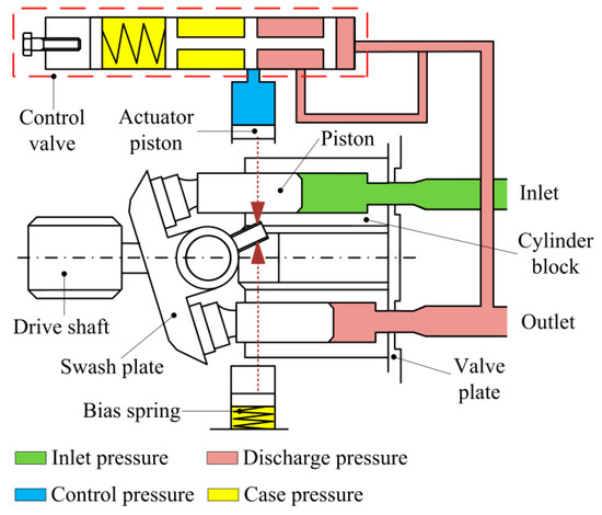
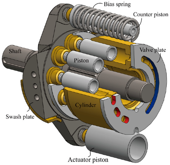
A cylinder block containing pistons that move in and out is housed within a piston pump. It’s the movement of these pistons that draw oil from the supply port and then force it through the outlet. The angle of the swash plate, which the slipper end of the piston rides against, determines the length of the piston’s stroke. While the swash plate remains stationary, the cylinder block, encompassing the pistons, rotates with the pump’s input shaft. The pump displacement is then determined by the total volume of the pump’s cylinders. Fixed and variable displacement designs are both available.
With a fixed displacement piston pump, the swash plate is nonadjustable. Its proportional output flow to input shaft speed is like that of a gear pump and like a gear pump, the fixed displacement piston pump is used within open center hydraulic systems.
As previously mentioned, piston pumps are also used within applications like snow and ice control where it may be desirable to vary system flow without varying engine speed. This is where the variable displacement piston pump comes into play – when the hydraulic flow requirements will vary based on operating conditions. Unlike the fixed displacement design, the swash plate is not fixed and its angle can be adjusted by a pressure signal from the directional valve via a compensator.
Vane pumps were, at one time, commonly used on utility vehicles such as aerial buckets and ladders. Today, the vane pump is not commonly found on these mobile (truck-mounted) hydraulic systems as gear pumps are more widely accepted and available.
Within a vane pump, as the input shaft rotates it causes oil to be picked up between the vanes of the pump which is then transported to the pump’s outlet side. This is similar to how gear pumps work, but there is one set of vanes – versus a pair of gears – on a rotating cartridge in the pump housing. As the area between the vanes decreases on the outlet side and increases on the inlet side of the pump, oil is drawn in through the supply port and expelled through the outlet as the vane cartridge rotates due to the change in area.
Input shaft rotates, causing oil to be picked up between the vanes of the pump which is then transported to pump outlet side as area between vanes decreases on outlet side and increases on inlet side to draw oil through supply port and expel though outlet as vane cartridge rotates
A clutch pump is a small displacement gear pump equipped with a belt-driven, electromagnetic clutch, much like that found on a car’s air conditioner compressor. It is engaged when the operator turns on a switch inside the truck cab. Clutch pumps are frequently used where a transmission power take-off aperture is not provided or is not easily accessible. Common applications include aerial bucket trucks, wreckers and hay spikes. As a general rule clutch pumps cannot be used where pump output flows are in excess of 15 GPM as the engine drive belt is subject to slipping under higher loads.
What separates this pump from the traditional gear pump is its built-in pressure relief assembly and an integral three-position, three-way directional control valve. The dump pump is unsuited for continuous-duty applications because of its narrow, internal paths and the subsequent likelihood of excessive heat generation.
Dump pumps are often direct mounted to the power take-off; however, it is vital that the direct-coupled pumps be rigidly supported with an installer-supplied bracket to the transmission case with the pump’s weight at 70 lbs. With a dump pump, either a two- or three-line installation must be selected (two-line and three-line refer to the number of hoses used to plumb the pump); however, a dump pump can easily be converted from a two- to three-line installation. This is accomplished by inserting an inexpensive sleeve into the pump’s inlet port and uncapping the return port.
Many dump bodies can function adequately with a two-line installation if not left operating too long in neutral. When left operating in neutral for too long however, the most common dump pump failure occurs due to high temperatures. To prevent this failure, a three-line installation can be selected – which also provides additional benefits.
Pumps for refuse equipment include both dry valve and Live Pak pumps. Both conserve fuel while in the OFF mode, but have the ability to provide full flow when work is required. While both have designs based on that of standard gear pumps, the dry valve and Like Pak pumps incorporate additional, special valving.
Primarily used on refuse equipment, dry valve pumps are large displacement, front crankshaft-driven pumps. The dry valve pump encompasses a plunger-type valve in the pump inlet port. This special plunger-type valve restricts flow in the OFF mode and allows full flow in the ON mode. As a result, the horsepower draw is lowered, which saves fuel when the hydraulic system is not in use.
In the closed position, the dry valve allows just enough oil to pass through to maintain lubrication of the pump. This oil is then returned to the reservoir through a bleed valve and small return line. A bleed valve that is fully functioning is critical to the life of this type of pump, as pump failure induced by cavitation will result if the bleed valve becomes clogged by contaminates. Muncie Power Products also offer a butterfly-style dry valve, which eliminates the bleed valve requirement and allows for improved system efficiency.
It’s important to note that with the dry valve, wear plates and shaft seals differ from standard gear pumps. Trying to fit a standard gear pump to a dry valve likely will result in premature pump failure.
Encompasses plunger-type valve in the pump inlet port restricting flow in OFF mode, but allows full flow in ON mode lowering horsepower draw to save fuel when not in use
Wear plates and shaft seals differ from standard gear pumps – trying to fit standard gear pump to dry valve likely will result in premature pump failure
Live Pak pumps are also primarily used on refuse equipment and are engine crankshaft driven; however, the inlet on a Live Pak pump is not outfitted with a shut-off valve. With a Live Pak pump, the outlet incorporates a flow limiting valve. This is called a Live Pak valve. The valve acts as an unloading valve in OFF mode and a flow limiting valve in the ON mode. As a result, the hydraulic system speed is limited to keep within safe operating parameters.
Outlet incorporates flow limiting valve called Live Pak valve – acts as an unloading valve in OFF mode and flow limiting valve in ON mode restricting hydraulic system speed to keep within safe operating parameters
Along with constantly improving performance, industrial machines continue to become increasingly sophisticated. Hydraulic equipment has to meet the challenge of diversifying needs.
You may already appreciate the Nachi-Fujikoshi reputation for compact equipment that delivers energy efficiency, safety, and high performance. Our equipment is also constantly refined by our quest for ultimate hydraulics that combine great power with flexible motion control.

The design of an axial piston unit is based on two important principles. First, the design of the axial piston pump may be based on the swash plate principle or bent axis design. Secondly, hydraulic system parameters have to be taken into account: whether the usage is to take place in an open or closed loop circuit is of great importance.
In fixed displacement volume configuration, the axial piston unit can be used both as pump and as motor. In bent axis design, the displacement volume is dependent on the swivel angle: the pistons move within the cylinder bores when the shaft rotates. In swash plate design, the rotating pistons are supported by a swash plate; the angle of the swash plate determines the piston stroke.
Hydraulic pumps are manufactured depending on different functional and hydraulic system requirements, such as operating medium, required range of pressure, type of drive, etc. Our sales engineers will assist you in selecting the most appropriate hydraulic pump for your application. Contact DTA for your hydraulic pump needs today!
Selecting the appropriate hydraulic pump for your application is always a challenge because of different available ranges and capabilities. DTA can help you select the correct pump within a reasonable price range and within your budget.
DTA has extensive expertise in hydraulic pump technology and carries a substantial inventory of hydraulic pumps from several different vendors. Depending on your requirements, DTA can supply high-quality hydraulic pumps, taking a wide variety of functional and hydraulic system requirements into account.
DTA is serving your industry with the supply of hydraulic parts and hydraulic components for more than 25 years. Since 2010 we have been fully qualified and certified as distributor hydraulics by Parker Hannifin. Together we developed a rapid delivery program for the genuine Denison Hydraulics single and multiple vane pumps. We support industrial and mobile applications and hold a considerable inventory of genuine parts, components and sub-assemblies.
Currently we can supply over 20,000 pump configurations from stock. All the hydraulic parts and components that we supply are new and genuinely manufactured by the high quality hydraulic manufacturer of your choosing. DTA can be your one-stop-shop and supplies high-quality brands only such as Parker Hannifin (Denison Hydraulics, Olaer, Calzoni, VOAC, Sterling Hydraulics), Bosch Rexroth (Brüninghaus, Eppensteiner, Hägglunds, Hydromatik, Oil-Control), Bucher Hydraulics, Moog, STAR Hydraulics, Hydac and Eaton (Char-Lynn, Eaton Hydraulics, Integrated Hydraulics, Vickers).

A hydraulic pump is literally the heartbeat of your hydraulic system. If you’re new to hydraulics, you’d be surprised at how many ways you can push fluid under pressure. The rotating and/or reciprocating of gears, vanes or pistons offer a designer constrained by any performance or budget envelope the options to best suit any application, especially since each of the primary pump construction styles offers unique options within each series.
Piston pump technology exclusively employs axially or radially reciprocating pistons relative to the input shaft. Fixed and variable displacement pumps are offered in all three primary construction variations — axial swashplate, bent-axis and radial. For both axial and bent-axis piston pumps, you will notice their pistons reciprocate in parallel as the rotating group orbits the shaft. Radial piston pumps look more like old wartime engines from aircraft, with their pistons reciprocating perpendicular to the input shaft. Although the most complicated design, piston pumps enjoy power and efficiency not possible in gear or vane pumps.
Axial-piston stylesThe fixed-displacement piston pump offers designers a relatively inexpensive entry point to the piston pump. They provide reliable, high-pressure fixed flow for open-circuit hydraulic systems with no fancy controls. However, the control options available to piston pumps offer many clever tactics to control your hydraulic system, from pressure compensation to electrohydraulic proportional control with onboard pressure transducers.
A pressure compensator is a relief valve for the control piston of the variable-displacement pump. The compensator is a very low flow component that essentially controls the swashplate angle to modify displacement in such a way as to maintain a set pressure. Any downstream flow demand lowers pressure drop at the pump, causing the pump to increase flow to maintain pressure. So long as downstream flow demand does not exceed the pump’s maximum flow rate, the pump can compensate and remain at full pressure. However, any flow exceeding its maximum rating will be subject to the downstream actuators’ load pressure.
Manufacturers offer various forms of displacement and pressure control. For example, load sensing control allows the pump to read downstream load pressure signals to reduce flow during off-demand periods and at reduced pressure equal to a few hundred psi higher than the highest load. A step further, you’ll find horsepower limiting (sometimes called torque or power limiting), which provides the machine maximum flow and pressure so long as the total demand is less than the prime mover’s capacity. Should a machine, such as an excavator, demand higher flow and pressure than the engine can supply, such as when multiple high-pressure actuators are simultaneously activated, the pump will automatically restrict flow to reduce the total power required.
Regardless of compensator type, each variation achieves its result by varying only the swashplate angle. For axial piston pumps, the swashplate pivots to increase or decrease displacement as required by the compensator as directed by the control piston. As a result, the control piston moves in the same axial plane as the rotating shaft, serving up a compact and powerful package.
Bent-axis piston technologyAlthough axial piston pumps are easily the most popular, other piston pump designs are offered with variable displacement. You may be aware of the bent-axis piston motor (Figure 1), which is famous for its high power and high-speed reputation. Its shaft and bearing assembly rotate at a taper relative to an axial piston motor. Despite their high-pressure design, the bent-axis configuration offers 25% higher rotational speed than straight-axis motors, and their bearing design is better suited to pulley or gear-driven applications. The force vector from a gear or pulley must oppose the bent direction of the motor (Figure 2), much like your arm pulling against a surgical band from underfoot to do bicep curls.
The tapered, oversized roller bearings inside a bent-axis piston motor provide superior side load protection to resist the steeply angled rotating group side load. For example, a swashplate on an axial piston motor may allow a maximum of 15-22° angle, while the bent axis piston motor operates at 40° or more. This extreme angle allows the motor to achieve high displacement in a small package, resulting in a high radial load on the input shaft. Resisting these side loads requires the heavy-duty tapered bearings like those you see in Figure 3 and explains the necessity to pull from the opposing direction as the motor angle.
The same benefits of the bent-axis piston motor apply to its pump kin. Superior power density, high-speed operation and high resistance to radial load make these the top choice for mobile hydraulic designs driven directly by diesel or gas engines. In addition, their inherently robust design makes them the top choice for gear or pulley-driven pump applications (as long as the installation recommendations are adhered to). Although the tapered roller bearings provide high side-load resistance, because the bearings are loaded to remove excessive clearances, excessive wear may occur. As a result, you’re more likely to replace the bearings on a bent-axis piston pump than in other designs.
You may be surprised to know that variable-displacement bent-axis piston motors are offered by manufacturers. Unfortunately, their appearance doesn’t seem to offer any place to mount any useful swashplate angling device. Their construction varies significantly from a swashplate variable-displacement pump, where instead of varying swashplate angle, the entire lens plate slides up and down inside the port plate.
A stroke piston opposed by a bias spring and control piston works much the same as in an axial piston pump. The compensator receives a pilot signal from the pressure port to balance the pressure drop at the pump’s outlet, varying the angle of the rotating group as required to maintain pressure.
The leading manufacturers of piston pumps offer most, if not all, control options for their bent-axis piston pumps. Basic pressure compensation with no other function often goes by pressure cut-off in product literature (or pressure override). The basic pressure cut-off control simply observes outlet pressure and adjusts the swashplate angle to alter flow rate, thereby maintaining a set pressure drop. So long as system demand is less than maximum flow, the outlet pressure remains at compensator set pressure. However, should demand rise above maximum pump flow, your circuit is at the mercy of the path of least resistance.
To be honest, selecting a pressure-compensated bent-axis piston pump for anything other than high-speed belt or pulley driven applications is an expensive bit of overkill. The control devices of variable-displacement bent-axis piston pumps are often quite advanced; you can expect various advanced controls such as horsepower limiting, hydraulic proportional control or even electro proportional control. I’m aware of one particular manufacturer that offers no less than seven kinds of horsepower-limiting controllers for one pump!
Proportional pump control uses proportional pressure-reducing valves in place of standard pressure compensators. For example, imagine a bent-axis piston pump where the spring offset stroke piston fights against spring pressure by infinitely varying the pressure inside the control side of the piston. Precise pressure observed by downstream transducers offers a closed-circuit feedback loop for the machine controller to adjust the proportional valve setting to match the desired outlet pressure. Some pumps may even take it a step further to include a linear transducer to provide precise displacement feedback, guaranteeing your circuit precise output flow and pressure despite fluctuations from the load, temperature, or viscosity.
With so many pump options on the market, do we really need so many advanced options for a single pump style? My vote is yes because the bent-axis piston pump offers unique advantages over other designs. The variety of control options available ensures that your system, no matter how complex, has the pump design you need.


 8613371530291