
vfd hydraulic pump for sale

In the current economy everyone has been feeling the pinch. ASI Hydraulics has been taking notes and has noticed the need for a “green” solution to powering the machinery that is required to run an efficient process. The need for a hydraulic power source that can effectively cut costs and endure for the long haul has finally be brought to the table and will be here to stay.

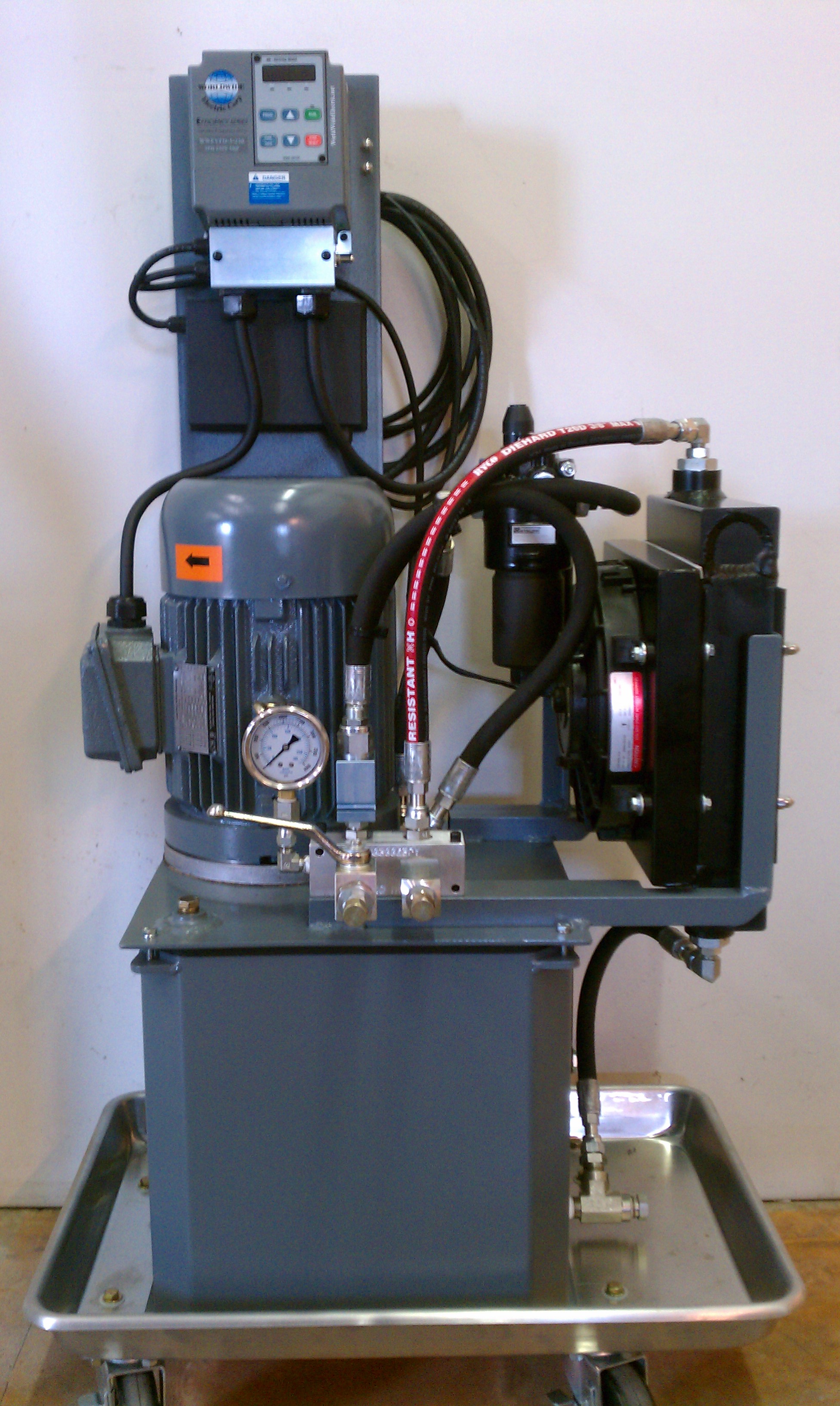
A hydraulic power unit (HPU) is a common product that IFP supplies to its customers for all types of hydraulic applications. Most customers order their HPUs with standard electric motors and across-the-line motor starters. These electric motors spin at a constant RPM. Because the electric motor spins at a constant RPM, the hydraulic pump coupled to the motor is constantly flowing oil and is likely wasting energy in between system operations.
By allowing the VFD controlled HPU to match the system pressure and flow requirements by varying the pump speed, there are several other advantages to using these VFD controlled HPU systems. By reducing energy put into the system, less heat is generated that has to be dissipated by the system. There are typically noise reductions with VFD controlled HPUs. With reduced heat and reduced system shock, this typically leads to longer component life depending on the load cycle. Hi-lo systems can now be completed with just one fixed displacement hydraulic pump. By over-speeding the pump for extra volumes of fluid, the VFD controlled system does not need a low pressure/high flow pump along with the high pressure/low flow pump. Charging an accumulator can become more efficient as well. Once the accumulator is charged, the VFD controlled HPU can slow down the flow output of the hydraulic pump and maintain the system. Unloading the pump for accumulator charging is typically done with extra valves and consuming unnecessary energy. Overall costs of hydraulic systems can be reduced because smaller hydraulic pumps can be used, less valves are required, less or no cooling for heat dissipation, and smaller reservoirs can be used.
The applications are endless for VFD controlled HPU systems. These systems can be used on anything from a simple filter and lubrication system to extremely complex test stands and presses. With increased efficiency and control, VFD controlled HPU systems will become more common in industry.
For more information on how you can utilize Drives and VFD controlled HPUs, please contact us here to receive a personalized contact by an IFP Application Engineer:

The Bear retrofitting of existing pumping stations means substantial energy savings, mainly when operating under partial loads, can be achieved. It can be efficiently transformed into any standard asynchronous pump motor suitable for variable speed drive operation.
The modular design of Bear makes it fundamentally different from ordinary variable speed pump drives. You can efficiently configure almost any pump arrangement according to your needs. It can up to six pumps be combined.
The cost saving is not only reflected in the energy-saving, which saves the customer’s use cost! The pump operation and monitoring protection logic is built into the Bear’s inverter so that it does not require additional relays or contactors; PLC can realize the function of controlling and protecting the water pump and motor; the operation is simple; no professional electrical engineer is required.
12/24 Volt DC hydraulic pump motors for sale, price cheap, 500W, 800W, 1.6 kW, 2.2 kW and 2.5 kW hydraulic pump motor for selection, hydraulic pump motor is widely used in dump trucks, fixed boarding bridges, lifting platforms, van wings, car lifts, vehicle headboards, etc. It has the characteristics of high speed and small rotational inertia, which is convenient for starting, braking, speed regulation and commutation.
Hydraulic motor and hydraulic pump, all with the help of sealing work in the capacity of the transformation to complete the kinetic energy, - the same with the flow distribution organization. Hydraulic motor in the keyed high-pressure liquid state effect, into the liquid cavity from the small increase, and the rotating components caused by the torque, in order to get rid of the load resistance torque, to complete the rotation; In addition, the motor back to the liquid cavity from the large shrinkage, to the car tank or pump suction pipe mouth back to the liquid, the work pressure is reduced. The pressure wave state continues to enter from the leakage port of the hydraulic motor, and discharge from the return port, then the motor rotor of the hydraulic motor rotates continuously and opens to the external work.
From the theory. In theory, in addition to the valve type hydraulic pump, other ways of hydraulic pump and hydraulic motor with cross, can be used. In fact, because the performance indicators and provisions are not the same, the same way the pump and motor in the structure is still different.
The hydraulic motor is keyed into the liquid containing the working pressure to promote its rotation, so it is necessary to ensure the original confinement, without having the ability of self-priming. While the hydraulic pump - generally must have self-priming ability.
Hydraulic motor should be able to forward and reverse, so the internal structure of the hydraulic transmission must be symmetrical. Hydraulic pump is generally all single-sided rotation, in the structure of the general do not have this limit.
Hydraulic motor speed than a large range, especially when the speed is relatively low, super piston hydraulic motor should be able to ensure that all the normal work, so should be selected with roller bearings or negative pressure rolling bearings, if the choice of gas pressure rolling bearings, it is not easy to produce grease film. And the hydraulic pump speed is relatively high, the general shift is small, there is no such provision.
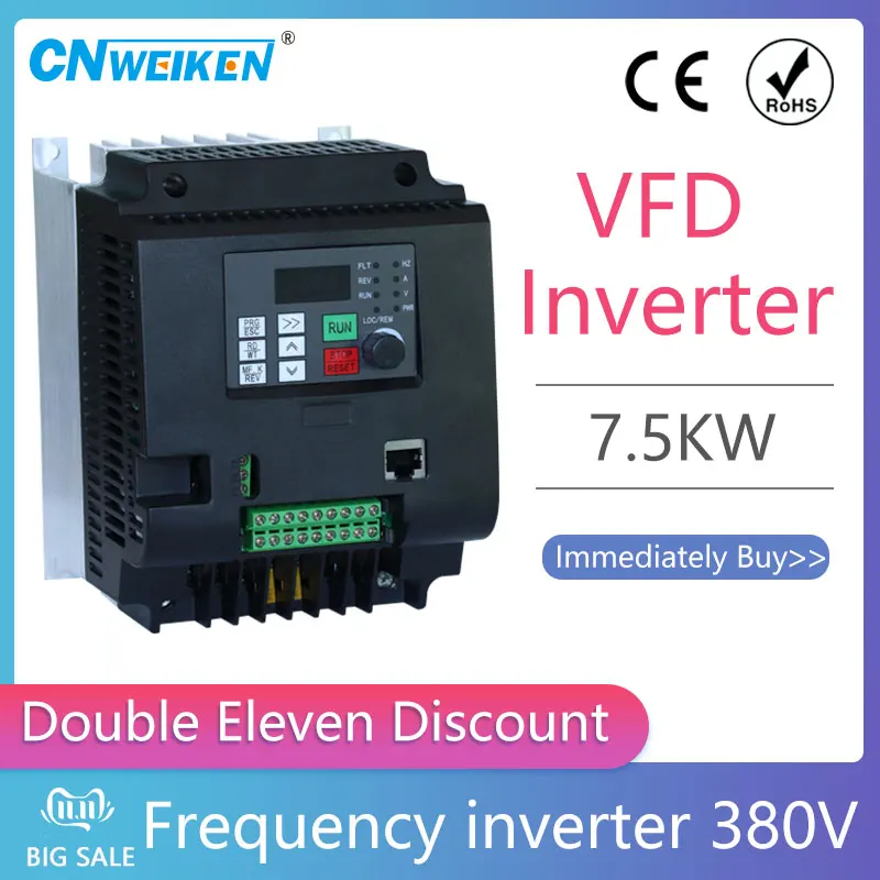
VFD technology was developed in response to the limitations of AC power. AC motors, such as the ones powering industrial pumps, rotate at a rate set by the incoming power and the number of poles inside the motor. Since AC power in the US is supplied at a standard 60 Hz frequency, this means that standard single phase two-pole motors spin 60 times per second.
Adding more sets of poles reduces the speed without any need to alter the incoming electrical frequency. However, you can’t just swap out an electric motor with more or fewer poles every time you need to change the operating speed of a pump. Transistor systems that allow you to turn specific motor poles on and off have been available for decades, but these systems are complex and often lack the fine control needed for industrial pumping. Instead, VFD’s change the frequency of the power supply, allowing for exact and immediate adjustments to the pump operation.
The VFD works by taking in AC power at the 60 Hz frequency, converts it into direct current (DC) power through a rectifier circuit, and sends it through a DC bus to filter the voltage further. Then, power reaches the inverter which creates pulses of DC energy that function like AC current. The pulsing nature of the output mimics AC power enough to create the correct induction processes needed to spin the rotor of the motor. Since DC is easier to control in voltage and frequency, using it instead of true AC power allows the VFD to adjust the electrical supply on the fly. A series of transistors, especially the Insulated Gate, Bipolar Transistor (IGBT), give manual or automatic control over the power output and the resulting EDDY pump performance. Power is easily increased to a sludge pump under heavy load and then dropped again after a blockage passes or the texture of the slurry or sludge being pumped changes.

A Variable Frequency Drive (VFD) is a versatile piece of machinery that can be used in a wide variety of applications. They can be used in pumps, motors, conveyors, air handlers, fans, and more. Anything that needs a varying speed or acceleration can be handled by a VFD.
Think of it like this: a VFD is similar to your foot on the gas pedal of your car. Your foot controls the acceleration and deceleration of your vehicle, which, in turn, varies the speed of the vehicle based on your needs. A VFD does that as well with whatever application it’s connected to. It will slow, stop, start, accelerate, and decelerate a system based on the needs of that system, function, or application.
While there are other ways to do this, a VFD is one of the most efficient ways to adjust speed and torque limit of a system. A VFD is able to better control the starting current of a system, which puts less wear on the motor. This can extend your motor’s life and reduce necessary maintenance (more on this later). The lower power demand that a VFD requires can also reduce your overall power usage.
VFD panels allow for overall increased control of acceleration and speed including easier/lower start speeds, programmable controllers, remote adjustment options, and improved stopping. Smoother VFD stopping mechanisms can reduce wear on mechanical components of the system and make processes safer for industrial and manufacturing applications.
Oftentimes businesses find that replacing or installing a VFD system as opposed to other systems can reduce the space the panel/drive takes up because they use fewer components. VFD drives don’t require a reverse starter, and many can eliminate the need for other equipment like hydraulic pumps and gearboxes.
Control valves in hydraulic pumps can also become sticky and/or suffer from control valve hysteresis. These downsides are eliminated with the use of a VFD panel. VFD drives are faster and more responsive than hydraulic pumps as well.
The reduced load that a VFD offers compared to a hydraulic pump system can also elongate the lifespan of your overall system as a result of less wear.
VFD panels can greatly increase your energy efficiency. They lower the necessary power demand on start, reduce overall power usage, and generally improve energy efficiency of your system.
However, it is worth noting that the scale of the energy efficiency a VFD panel or system will provide depends on your particular application, industry, uses, and more. You can ask us any question about how you can expect your energy efficiency to change with the use/installation of a VFD panel or system.
VFDs reduce energy waste by smoothly controlling speed and only using the energy it requires instead of energy/power overuse that can occur with other speed control systems.
Perhaps the most obvious would be connected to the energy efficiency of a VFD panel. Reduced power use and/or energy consumption can reduce your energy spending.
The lowered maintenance requirements and fewer components of a VFD system can also reduce expenses related to upkeep of the system. Longer motor life and less wear on components can also reduce costs associated with this system.
Various states also offer potential financial rebates for VFD installation, which can reduce your overall costs and give you the long term benefits of VFD panels.
VFD benefits range from energy efficiency to prolonged life to noise reduction. They’re also excellent for their versatility and their ability to be customized for each business and each application.

At NPE2018, both Jomar Corp., Egg Harbor Township, N.J., and Bosch Rexroth Corp., Bethlehem, Pa., introduced new products that provide an educational illustration of the differences between two types of energy-saving variable-speed drives for hydraulic pumps.
The term “servo-hydraulic” has gained currency to describe new generations of plastics machinery that utilize hydraulic pumps but with energy savings and noise reduction closely approaching those obtained with all-electric servo motors and drives. At the same time, popularity has also been growing for aftermarket retrofits of conventional hydraulics with variable-frequency drives (VFDs), another way of saving energy by varying pump speed—even to zero—according to the instantaneous load demand of the system.
Bosch Rexroth introduced at the show its Sytronix DRn 5020 VFD, aimed specifically for converting variable-displacement hydraulic pumps driven by conventional fixed-speed (1800 rpm) motors to quieter, more energy-efficient variable-speed operation. It reportedly saves up to 75% in electrical energy for systems that have long dwell times; and the average noise reduction is 8 to 10 dBa vs. fixed-speed hydraulic drives. This “intelligent” drive senses the motor torque and pump pressure to calculate the pump displacement, or position of the swash plate, to keep it in the most efficient position for the real-time load requirement. This drive is Industry 4.0 compatible, as it adds operating data collection and digital communications to conventional electric motors and hydraulic pumps that normally do not have these capabilities.
Bosch Rexroth notes that VFDs are considerably less expensive than servo drives, but the firm also points out in a white paper that they provide less tight control over motor speed than servos and have lower dynamic performance—ability to respond and control pressure/velocity changes. VFD drives are thus more suited to steady or slowly changing loads. They also have low-speed limitations and are usable only to 400-500 rpm.
Bosch Rexroth points to an instructive use of both its MSK servo motor and the new Sytronix DRn 5020 on Jomar’s new IntelliDrive injection-blow molding machines. Jomar often refers to these machines as “servo-hydraulic,” but the servo drives only the hydraulic pump for the injection unit. The injection and blowing clamps use a pump with the new VFD. The Jomar IntelliDrive 85S at the show boasted 42% lower energy consumption than a standard model 85S and required a 40% smaller oil tank.

Centrifugal pumps are generally sized to operate at or near the best efficiency point at maximum flow. The maximum flow requirements, however, frequently occur for a very short period during the operating cycle with the result that some method of flow control is required. The traditional method to flow control has used valves, which increase system pressure, inherently waste energy, and generally cause the centrifugal pump to operate at reduced efficiencies.
VFDs (Variable Frequency Drives) can achieve reduced flow by providing variable speed pump operation. This results in reduced system pressure and operation near the pump"s Best Efficiency Point. In addition, maintenance costs might be reduced. This article will discuss the energy savings potential of variable frequency drives followed by a brief description of the operation and relative benefits of VFDs.
Centrifugal pumps are used on many industrial and commercial applications. Many of these pumps are operated at fixed speeds, but could provide energy savings through variable speed operation. Reviewing the affinity laws for centrifugal pumps and a typical operating cycle for a centrifugal application will show this.
Figure 1 shows the physical laws of centrifugal pumping applications. The flow is directly proportional to speed; pressure is proportional to the square of the speed; and power is proportional to the cube of the speed. These relationships can also be expressed numerically as shown in Table 1. Theoretically, it would be possible to operate at 50% flow with only 13% of the power required at 100% flow. Since the power requirements decrease much faster than the reduction in flow, the potential exists for significant energy reduction at reduced flows.
These characteristics are important when one considers a typical duty cycle for a centrifugal pump application. A typical operating cycle might be represented by the bar chart shown in figure 2. Centrifugal pumps are generally sized to handle the peak flow requirements, which typically occur for very short periods of time. Consequently, the equipment would be operated at reduced flows most of the time. For this example, the system would be operated below 70% flow over 94% of the time. Thus, this sort of duty cycle could provide energy savings by variable speed operation of the centrifugal pump.
An understanding of the basic operating characteristics of centrifugal pumps is necessary to apply variable frequency drives to this particular application.
Figure 3 shows a centrifugal pump curve describing the head (or pressure) versus flow characteristics of a typical centrifugal pump. This curve shows that the centrifugal pump will produce limited flow if applied to a piping system in which a large pressure differential is required across the pump to lift the liquid and overcome resistance to flow (as at point A). Higher flow rates can be achieved as the required pressure differential is reduced (as at point B).
To determine where along this curve the centrifugal pump will operate in a given application requires the additional information provided by the system curve. This curve, shown in figure 4, represents the characteristics of the piping system to which the centrifugal pump is applied. The head required at zero flow is called the static head or lift.
This shows how many feet of elevation that the centrifugal pump must lift the fluid regardless of the flow rate. Another way to describe static head is to think of it as the amount of work needed to overcome the effects of gravity.
The intersection of the centrifugal pump and system curves shows the natural operating point for the system without flow control, as shown in figure 5. This intersection would generally be chosen to ensure that the centrifugal pump is operated at or near its best efficiency point.
Figure 6 shows a typical centrifugal pump and efficiency curve for operation at a fixed speed. It can be seen that for fixed speed operation, the efficiency varies as flow is adjusted. For variable speed operation however, the affinity laws predict that the centrifugal pump curve will shift downwards for reduced speed and the efficiency curve will shift to the left in such a way that efficiency will remain constant relative to points on the pump curve for reduced flows.
Historically, fixed speed AC motors have driven centrifugal pumps and reduced flow has been achieved by using control valves as shown in figure 7. Closing the valve reduces the flow by increasing the friction in the system. The modified system curve and the new operating point can be represented as shown in figure 8. Note that the desired reduction in flow has been achieved, but at the expense of increased system pressure relative to 100% flow.
Reducing the centrifugal pump speed causes the pump curve to shift downwards as shown in figure 9. Since the operating point is still determined by the intersection of the reduced speed pump curve and the system curve, it is possible to achieve the same reduced flow as achieved with a valve, but at significantly less pressure.
In addition to energy savings by VFD, which are discussed in detail later, operation at reduced pressures can result in longer pump seal life, reduced impeller wear, and less system vibration and noise. These benefits could provide additional savings over potential energy savings by variable frequency drive.
Therefore, for any given liquid, the power that the centrifugal pump must transmit is proportional to the head times the flow and can be represented by rectangles for each operating point as shown in figure 10.
The valve control rectangle includes both the dark and light shaded areas. Speed control uses only the lighter shaded portion of horsepower. Therefore, the potential energy saving available at this particular flow point is represented by the darker rectangle. This situation results in a substantial reduction in output power required through the use of variable frequency drive control rather than valve control (see differences between VFD and valve control). Relating this reduction in required output power to input power, which is the basis for the user"s power bill, requires consideration of the efficiency of the centrifugal pump and flow control elements.
(2) Slip control refers to fluid and magnetic couplings, often referred to as hydraulic or eddy current couplings. Wound rotor motors are also slip devices.
Thus, the first step toward realizing energy savings on centrifugal pumping applications is the decision to use VFD for pumps. The second step is to use the most efficient VFD that meets the application requirements.
VFD energy losses can vary substantially between VFD types, Solid-state drives have much lower losses than slip devices and closely approximate ideal, 100% efficient operating characteristics as shown in figure 11.
Centrifugal pump efficiencies at various operating points are readily available from the pump manufacturer in the form of an efficiency map superimposed over the centrifugal pump curves for various impeller sizes as shown in figure 12.
The state-of-the-art has progressed dramatically in electronics in recent years. Advances in logic have produced large scale integrated and microprocessor devices that will continue to increase the capability of VFDs. Improvements in thyristors have resulted in decreased size while the development of IGBTs have expanded capabilities and size ranges. VFDs are expected to continue decreasing in cost and increasing in performance in the years to come. Besides longer-term energy savings, the initial cost differential between installing a VFD / motor package as compared to an AC starter/motor package is continually diminishing.
Dramatic increases in energy costs in recent years have made variable speed flow control through the use of VFDs economical in many instances. Large users of centrifugal pumping equipment would be wise to begin gaining experience with these VFDs now.
The most important choice to be made in choosing the VFDs is the decision to select a non-slip, solid-state VFD. Any such VFD can offer dramatic energy savings by efficiently matching the energy consumed to the hydraulic load requirements at any given moment.
In general, if the electrical engineer does not fully understand the operation variables of the pumping operation, he will not be able to design a proper operation and protection gear.I highly ...
Mechanical VFDs include the following subtypes:Variable pitch drive – a belt and pulley drive where the pitch diameter of one or both pulleys is adjustable, giving a multi ratio and hence a ...
There are two ways in tension control, one way is to control the output torque of the motor, the other way is to control the motor speed. Variable frequency drive (VFD) open-loop control mode is ...

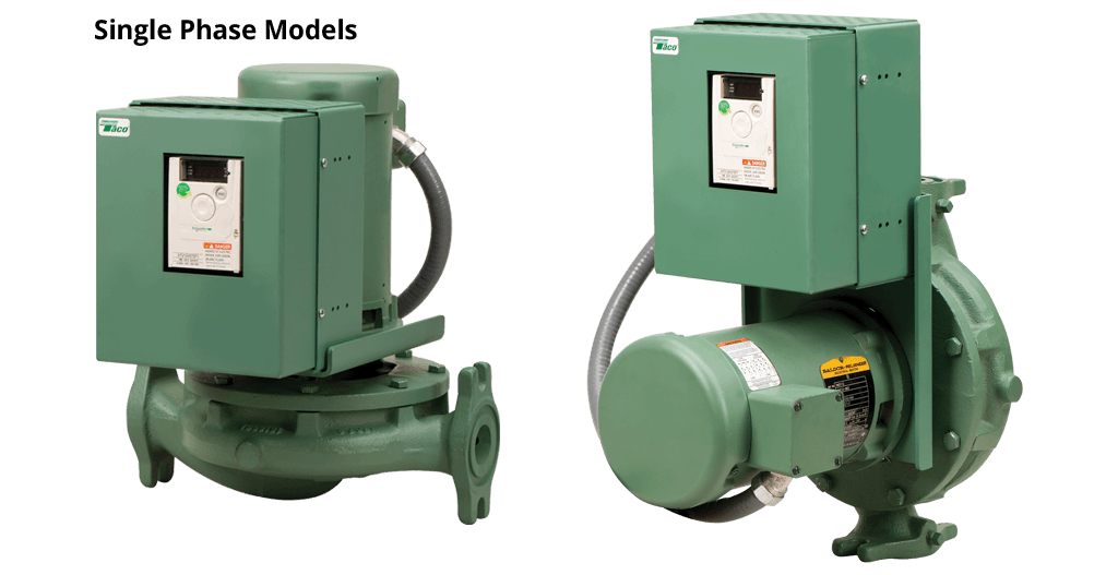
The 1900 VFD Series Close-Coupled In-Line Pumps meet the latest industry standards for hydraulic performance and reliability. The 1900 VFD Series Close-Coupled In-Line Pumps are compact, energy efficient and can be installed anywhere in the piping layout.
Let the variable frequency drive (VFD) on the 1900 VFD Series Close-Coupled In-Line Pump operate your buildings with greater efficiency; using them to control your pumps can significantly reduce energy costs. Most HVAC systems are designed to keep the building cool on the hottest days and warm on the coldest days. Therefore, the HVAC system only needs to work at full capacity on the 10 or so hottest days and the 10 or so coldest days of the year. On the other 345 days, the HVAC system may operate at a reduced capacity. This is where a system with variable frequency drives (VFDs) can be used to match system flow to actual heating and cooling demands. The VFD can reduce the motor speed when full flow is not required, thereby reducing the power required and the electrical energy used.
There are some applications where a pump must discharge into a closed system to meet continuously varying demands where a variable speed pump could pay for itself in a short time. But what about water and wastewater systems?
(First, a digression. There is no such thing as a variable speed pump. A pump is a pump. What constitutes variable-speed pumping is a variable-speed motor attached to a pump. A variable frequency drive (VFD) is the best technology these days to produce variable speed. So, I’ll call the pump, VFD and motor together as a variable speed pump.)
The selection of the pumping technology should be based on life cycle costs (plus some other considerations) and depends heavily on the nature of the pumped system. There are essentially two types of systems – those that have floating storage and those that don’t. This makes a big difference in the type of analysis required.
Systems with storage have a significant advantage in pumping in that it is possible to turn the pumps(s) OFF. This storage can refer to an elevated water storage tank or a sewage wet well. If you correctly select the right constant speed pump, you can run it at an efficient operating point to fill the storage tank or drain the wet well and turn it off. I’ve done a lot of calculations along these lines, and constant speed pumping almost always wins.
But as with everything else in life, there are exceptions to the rules. The first exception depends on the shape of the system head curve. Most water, and to a lesser extent, sewage pumping involves a fairly flat system head curve. Water is lifted from one pressure zone to the next higher one or lifted over a drainage divide. It is very difficult to turn down the speed without seriously hurting the efficiency. However, if you are pumping across flat ground, most of the energy is used to overcome friction, and the flow can be adjusted without having as much detrimental effect on efficiency. The friction-dominated case may favor a variable speed pump.
In systems without storage, it’s not possible to turn pumps off, so the pump station must meet the instantaneous demand. This means that during low demands, a constant speed pump would need to run far to the left on its curve and the pump would be pumping at a high head and low efficiency. A variable speed pump would be the clear winner—but not always.
The pump station must meet peak demand with the largest unit out of service. The typical configuration for a small to medium pump station is usually two pumps, with each sized to meet peak demands. But, in most situations, the peak demand rarely occurs, and the one running pump is running at low efficiency, especially during low flow periods.
Is there a better configuration than these two pump solutions? Enrico Creaco and I (Walski and Creaco, 2016) tested a wide range of configurations (see below) over a wide range of flow in a paper we wrote using WaterGEMS to calculate life-cycle energy costs.
As expected, the configuration with two constant speed pumps had the worst life-cycle cost. But surprisingly, the second-worst was the two variable pump setup that pretty much everyone uses. Configurations with three pumps (or for very small systems, two pumps, and a hydropneumatics tank) proved to be better than two variable speed pumps. All the three pump configurations were fairly close to one another in cost. The reason they were so good was that their best efficiency point could be matched fairly well with the most common demands with only one pump running. For those cases, where demands were high, simply turn on the second pump until the demand drops.
A lot depends on the actual flow distribution that the pump station will encounter. If the peak flow is 800 gpm and the average flow is 750 gpm, then any configuration will work well. However, if the peak flow is 800 gpm and the average flow is 200 gpm, then it will be virtually impossible to make the two-pump designers work efficiently.
In an earlier blog (Abusing Affinity, 4 March 2021), I mentioned how the calculations of head and efficiency for variable speed pumps are governed by the pump affinity laws, and sometimes those folks selling VFDs misrepresent the affinity laws to make their product look more beneficial than it really is.
Another issue is the fact that the VFDs themselves introduce a certain amount of inefficiency. They work by breaking up the smooth sine wave of alternating current into pieces and reassembling those pieces in a sine wave with a lower frequency, thus varying the pump speed. The problem is that this reformulated output wave is less than 100% efficient. This loss of efficiency is sometimes called the “parasitic energy demand of the VFD”. VFD salespeople don’t like to talk about this, and if you ask them for data about VFD efficiency, they will only provide data at 100% of full speed, which is not the case you’re looking for, or respond along the lines of.” Hey, do you think the Chiefs will win the Super Bowl next year?”
How do you decide on the best configuration for your pump station? I’ve been trying for years to come up with some rules-of-thumb to decide on the best configuration, and the best I could come up with are the paragraphs above.
What you need to do as a conscientious engineer is try many designs to arrive at the best pump selection. The most tedious step in a good evaluation is calculating the life-cycle energy cost because the pumps must work over a range of conditions. In my early days, I did these calculations manually, and you needed to make a lot of simplifications to make the effort feasible. Later, I graduated to spreadsheet calculations, but that still didn’t capture all the hydraulic and cost variability. Now, if you start with a well-calibrated model, WaterGEMS and WaterCAD can give you the results you need with a few mouse clicks.
Walski, T. and Creaco, E., 2016, “Selection of Pumping Configuration for Closed Water Distribution Systems”,Journal of Water Resources Planning and Management,142(6), DOI: 10.1061/(ASCE)WR.1943-5452.0000635.


 8613371530291