
volumetric efficiency hydraulic pump price

In a condition-based maintenance environment, the decision to change out a hydraulic pump or motor is usually based on remaining bearing life or deteriorating efficiency, whichever occurs first.
Despite recent advances in predictive maintenance technologies, the maintenance professional’s ability to determine the remaining bearing life of a pump or motor, with a high degree of accuracy, remains elusive.
Deteriorating efficiency on the other hand is easy to detect, because it typically shows itself through increased cycle times. In other words, the machine slows down. When this occurs, quantification of the efficiency loss isn’t always necessary. If the machine slows to the point where its cycle time is unacceptably slow, the pump or motor is replaced. End of story.
In certain situations, however, it can be helpful, even necessary, to quantify the pump or motor’s actual efficiency and compare it to the component’s native efficiency. For this, an understanding of hydraulic pump and motor efficiency ratings is essential.
There are three categories of efficiency used to describe hydraulic pumps (and motors): volumetric efficiency, mechanical/hydraulic efficiency and overall efficiency.
Volumetric efficiency is determined by dividing the actual flow delivered by a pump at a given pressure by its theoretical flow. Theoreticalflow is calculated by multiplying the pump’s displacement per revolution by its driven speed. So if the pump has a displacement of 100 cc/rev and is being driven at 1000 RPM, its theoretical flow is 100 liters/minute.
Actualflow has to be measured using a flow meter. If when tested, the above pump had an actual flow of 90 liters/minute at 207 bar (3000 PSI), we can say the pump has a volumetric efficiency of 90% at 207 bar (90 / 100 x 100 = 90%).
Its volumetric efficiency used most in the field to determine the condition of a hydraulic pump - based on its increase in internal leakage through wear or damage. But without reference to theoretical flow, the actual flow measured by the flow meter would be meaningless.
A pump’s mechanical/hydraulic efficiency is determined by dividing thetheoretical torque required to drive it by the actual torque required to drive it. A mechanical/hydraulic efficiency of 100 percent would mean if the pump was delivering flow at zero pressure, no force or torque would be required to drive it. Intuitively, we know this is not possible, due to mechanical and fluid friction.
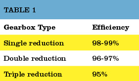
Table 1. The typical overall efficiencies of hydraulic pumps, as shown above, are simply the product of volumetric and mechanical/hydraulic efficiency.Source: Bosch Rexroth
Like theoretical flow, theoretical drive torque can be calculated. For the above pump, in SI units: 100 cc/rev x 207 bar / 20 x p = 329 Newton meters. But like actual flow, actual drive torque must be measured and this requires the use of a dynamometer. Not something we can - or need - to do in the field. For the purposes of this example though, assume the actual drive torque was 360 Nm. Mechanical efficiency would be 91% (329 / 360 x 100 = 91%).
Overall efficiency is simply the product of volumetric and mechanical/hydraulic efficiency. Continuing with the above example, the overall efficiency of the pump is 0.9 x 0.91 x 100 = 82%. Typical overall efficiencies for different types of hydraulic pumps are shown in the Table 1.
System designers use the pump manufacturers’ volumetric efficiency value to calculate the actual flow a pump of a given displacement, operating at a particular pressure, will deliver.
As already mentioned, volumetric efficiency is used in the field to assess the condition of a pump, based on the increase in internal leakage due to wear or damage.
When calculating volumetric efficiency based on actual flow testing, it’s important to be aware that the various leakage paths within the pump are usually constant. This means if pump flow is tested at less than full displacement (or maximum RPM) this will skew the calculated efficiency - unless leakage is treated as a constant and a necessary adjustment made.
For example, consider a variable displacement pump with a maximum flow rate of 100 liters/minute. If it was flow tested at full displacement and the measured flow rate was 90 liters/minute, the calculated volumetric efficiency would be 90 percent (90/100 x 100). But if the same pump was flow tested at the same pressure and oil temperature but at half displacement (50 L/min), the leakage losses would still be 10 liters/minute, and so the calculated volumetric efficiency would be 80 percent (40/50 x 100).
The second calculation is not actually wrong, but it requires qualification: this pump is 80 percent efficient at half displacement. Because the leakage losses of 10 liters/minute are nearly constant, the same pump tested under the same conditions will be 90 percent efficient at 100 percent displacement (100 L/min) - and 0 percent efficient at 10 percent displacement (10 L/min).
To help understand why pump leakage at a given pressure and temperature is virtually constant, think of the various leakage paths as fixed orifices. The rate of flow through an orifice is dependant on the diameter (and shape) of the orifice, the pressure drop across it and fluid viscosity. This means that if these variables remain constant, the rate of internal leakage remains constant, independent of the pump"s displacement or shaft speed.
Overall efficiency is used to calculate the drive power required by a pump at a given flow and pressure. For example, using the overall efficiencies from the table above, let us calculate the required drive power for an external gear pump and a bent axis piston pump at a flow of 90 liters/minute at 207 bar:
As you’d expect, the more efficient pump requires less drive power for the same output flow and pressure. With a little more math, we can quickly calculate the heat load of each pump:
No surprise that a system with gear pumps and motors requires a bigger heat exchanger than an equivalent (all other things equal) system comprising piston pumps and motors.

Hydraulic pumps convert mechanical energy into hydraulic energy. A high-performance piston pump can convert mechanical energy into hydraulic energy with an efficiency of 92 percent.
If the pump drives a piston motor, the motor is able to convert this hydraulic energy back into mechanical energy with an efficiency of 92 percent. The overall efficiency of this hydraulic drive, without considering flow losses, is 85 percent (0.92 x 0.92 x 100 = 85).
The inefficiencies or losses in a hydraulic drive can be divided into two categories: hydraulic-mechanical, which comprise flow and mechanical friction losses, and volumetric, which comprise leakage and compressibility losses (Figure 1).
The advantages of a hydraulic drive, which include high-power density (high-power output per unit mass), variable speed control, simple overload protection and both rotary and linear motion, are possible from a single system.
As Table 1 shows, a key disadvantage of a hydraulic drive is that it is far less efficient than a mechanical drive. What’s worse, the wear process decreases a hydraulic drive’s volumetric efficiency (and therefore total efficiency) causing the drive to slow down and more energy to be given up to heat.
The hydraulic pump is usually the hardest working component of a hydraulic system. As the pump wears in service, internal leakage increases and therefore the percentage of theoretical flow available to do useful work (volumetric efficiency) decreases. If volumetric efficiency falls below a level considered acceptable for the application, the pump will need to be overhauled.
In a condition-based maintenance environment, the decision to change-out the pump is often based on remaining bearing life or deterioration in volumetric efficiency, whichever occurs first.
Volumetric efficiency is the percentage of theoretical pump flow available to do useful work. In other words, it is a measure of a hydraulic pump’s volumetric losses through internal leakage and fluid compression. It is calculated by dividing the pump’s actual output in liters or gallons per minute by its theoretical output, expressed as a percentage. Actual output is determined using a flow-tester to load the pump and measure its flow rate.
Because internal leakage increases as operating pressure increases and fluid viscosity decreases, these variables should be included when stating volumetric efficiency. For example, a hydraulic pump with a theoretical output of 100 GPM, and an actual output of 94 GPM at 5,000 PSI and 46 cSt is said to have a volumetric efficiency of 94 percent at 5,000 PSI and 46 cSt.
In practice, fluid viscosity is established by noting the fluid temperature at which actual pump output is measured and reading the viscosity off the temperature/viscosity graph for the grade of fluid in the hydraulic system.
When calculating the volumetric efficiency of a variable displacement pump, internal leakage must be expressed as a constant. Consider this example: I was recently asked to give a second opinion on the condition of a large, variable displacement pump. My client had been advised that its volumetric efficiency was down to 80 percent and based on this advice, he was considering having the pump overhauled.
The hydraulic pump in question had a theoretical output of 1,000 liters per minute at full displacement and maximum rpm. Its actual output was 920 liters per minute at 4,350 PSI and 46 cSt. When I advised my client that the pump’s volumetric efficiency was in fact 92 percent he was alarmed by the conflicting assessments. To explain the disparity, I asked to see the first technician’s test report.
The technician had limited the pump’s displacement to give an output of 400 liters per minute (presumably the maximum capacity of his flow-tester) at maximum rpm and no load. At 4,350 PSI the recorded output was 320 liters per minute. From these results, volumetric efficiency had been calculated to be 80 percent (320/400 x 100 = 80).
To help understand why this interpretation is incorrect, think of the various leakage paths within a hydraulic pump as fixed orifices. The rate of flow through an orifice is dependent on the diameter (and shape) of the orifice, the pressure drop across it and fluid viscosity. This means that if these variables remain constant, the rate of internal leakage remains constant, independent of the pump’s displacement.
Note that in the above example, the internal leakage in both tests was 80 liters per minute. If the same test was conducted with pump displacement set to 100 liters per minute at no load, pump output would be 20 liters per minute at 4,350 PSI - all other things equal.
This means that this pump has a volumetric efficiency of 20 percent at 10 percent displacement, 80 percent at 40 percent displacement and 92 percent at 100 percent displacement. As you can see, if actual pump output is measured at less-than-full displacement (or maximum rpm), an adjustment needs to be made when calculating volumetric efficiency.
In considering whether it is necessary to have this hydraulic pump overhauled, the important number is volumetric efficiency at 100 percent displacement, which is within acceptable limits. If my client had based his decision on volumetric efficiency at 40 percent displacement, his company would have paid thousands of dollars for unnecessary repairs.

Gear pumps have very few moving parts. They consist of two intermeshing gears. These pumps have a constant flow rate. They operate at pressures generally between 50 and 210 bar. Gear pumps operate at the highest speeds of any pumps at up to 3000-6000 rpm.
In an external-gear pump, only one of the gear wheels, the drive gear, is connected to the drive. The other gear wheel, the driven gear, rotates in the opposite direction, so that the teeth of the rotating gear wheels interlock.
There are also double external-gear pumps, which combine two gear pumps driven by the same coupling shaft. A double external-gear pump has the advantage of supplying two independent hydraulic circuits, and also provides more flow to one circuit.

Hydraulics are essential in many industrial applications; they use mechanical energy to force liquid into a system. Within the category of hydraulics, there are many different types of hydraulic pumps that accomplish various tasks within industrial fields. Let’s take a look at some of them.
An axial piston hydraulic pump is also a positive displacement pump. Axion pumps have cylinders that are assembled around a central axis (cylinder block). Within each cylinder, there are pistons which will attach to a swashplate or wobble plate. These swashplates then connect to the rotating shaft, which moves the pistons and pulls them in and out of the cylinders.
Axial piston pumps can also be made into variable displacement piston pumps, which provide more control over speed. In variable pumps, the swashplate is used to set the depth of the pistons, which creates a length variation to affect the discharge volume. This design helps maintain constant discharge rates in industrial applications.
Another hydraulic pump type is the radial piston pump. As the name suggests, the pistons are arranged along the radius of the cylindrical block, which includes the pintle and rotor. The rotor powers the pistons through the cylinders and forces hydraulic fluid in and out of the cylinder.
Both axial and radial piston pumps are used for high-operating pressures as they can withstand much higher pressures than hydraulic pump types. They are often used in ice and snow control applications, as well as on truck-mounted cranes.
A rotary vane pump is also a type of positive displacement pump. It uses rigid vanes rather than the rotor hubs. These vanes are placed around an eccentric rotor device, which moves around the inside wall of the housing container. This movement forces the hydraulic fluid through the discharge port, and, in some applications, can be adjusted to align with the rotational axis of the motor.
Vane pumps are often used in utility vehicles but have lost popularity over the years in favor of gear pump hydraulic systems. However, they used to be very common in aerial buckets and ladders along with other mobile, truck-mounted hydraulic applications.
Gear pumps have become the most common hydraulic pump type that’s used in industrial applications today. The gear pump has fewer moving parts than piston or vane pumps, which makes it easy to service and relatively inexpensive compared to other hydraulic pumps. They are also less likely to be contaminated during use.
An external gear pump uses two gears on the outside of individual shafts to aid in movement and push both thin and thick fluids through the gears. These external pumps are commonly used in fixed-displacement applications and high-pressure environments.
Internal gear pumps place gears on the insides of the shafts rather than on the outside as found in external gear pumps. That makes them self-priming and non-pulsing, and can even be run without liquid for short periods of time—although they can’t be left dry for too long.
Additionally, internal gear pumps are bi-rotational, meaning that one can be utilized to both unload and load devices. And, with only two moving parts, they are considered to be one of the most reliable types of hydraulic pumps.
Volumetric efficiency is the amount of output the pump actually produces as a percentage of its theoretical production.The higher the percentage the more efficient the pump.
Among the factors affecting volumetric efficiency are leakage and fluid compressibility (ability for volume to be reduced under pressure). These issues can cause the pump to lose efficiency and waste energy as that energy converts to heat.
Still have questions about hydraulic pumps or their parts and repairs? Contact Panagon Systems today. We’ve been a leading hydraulic pump manufacturer in the U.S. for over two decades, and can help you find the best solution for your application. You can view our full line of pumps here. To request a consultation or quote, please fill out our online form.

?I just love this newsletter. As a Hydraulics Instructor for Eaton, I make copies and distribute them to my students as I address various topics. Please keep "em coming.?

While it’s not usually possible to see inside a hydraulic pump and motor assembly and observe the wear taking place, there is one surefire clue that makes it possible to know if these important components are on their way out. Declining efficiency is a sign of leakage and/or increased internal friction, which is why keeping an eye on the efficiency of your pumps is a good way to monitor the health of your equipment. In this article, we’ll explore two aspects of hydraulic pump and motor efficiency and what they can tell you about what’s going on inside. Allowing you to repair and replace worn units in time to avoid costly failures.
Every new pump or motor has a specified ‘theoretical’ flow and torque rating. These are the numbers the unit should be able to achieve in a perfect world. However, the real world is never perfect and in reality, things like friction will mean that your actual performance will always be somewhere below the ideal theoretical number.
In addition, over the lifespan of the unit, various components such as bearings, pump elements, fluid, and other internals begin to deteriorate and as this happens, the pump gradually becomes less efficient. This deterioration can be measured in relation to the specified performance of the pump. This is useful to understand because it’s a clear indication of pump wear and gives us a valuable clue to alert us to repair or replace these units before its too late.
We can measure this loss of efficiency by looking at two aspects of efficiency, which are hydro-mechanical efficiency and volumetric efficiency. Each of these tells us something about the condition of the pump/motor and whether it is likely to fail in the near future.
In layman’s terms, Volumetric Efficiency refers to the amount of fluid a pump delivers and it is usually measured in litres per minute. In ideal conditions, a positive-displacement pump should deliver the same amount of liquid for each rotating cycle. As the unit wears, fluid slippage slowly increases and the amount of liquid delivered per cycle decreases. Thus, a decrease in volumetric efficiency indicates losses due to leakage or bypass. The decline in volumetric efficiency is accompanied by an increase in the cycle time of actuators such as hydraulic cylinders as the flow has been slowed. If the degradation is allowed to continue, the hydraulic system may become completely inoperable, requiring the repair or replacement of the worn pumps and motors to get up and running again.
The second category to look at is hydro-mechanical efficiency, which indicates the amount of fluid and mechanical friction within the system. To determine a motor’s hydro-mechanical efficiency, look at the actual torque output compared to the unit’s rated torque output. If a motor’s real-world output is 20% below its theoretical torque rating, then the motor can be said to be 80% efficient. A reduction in actual torque is, therefore, a sign that bearings and other mechanical internals are becoming worn and generating more friction.
Hydraulic pump and motor efficiency can have a significant effect on your hydraulic system. Inefficient components draw more power and drive up the running costs of your operation, so always a good idea to be aware of how your equipment is performing. However, declining efficiency is also an important way to monitor the health of your hydraulic pumps and motors. Warning signs such as slowing hydraulic actuators and loss of torque are a symptom of decreasing efficiency that – if left unchecked – will eventually lead to failure of hydraulic equipment. These components will eventually need to be repaired or replaced, but in the long term it’s more cost-effective to do so before they fail or start to inflate operating expenses.

Although many detractors sneer at the idea of hydraulic efficiency, right-sizingcomponents, proper system design and moderntechnology can go a long way to achieving system efficiency.
“Hydraulic efficiency”is a term alluding similar sentiments to “exact estimate” or “scientific belief.” It’s not that hydraulic efficiency is an oxymoron, per se, but these aren’t traditionally two words that make sense shoulder to shoulder. If efficiency was your top benefit on the list of machine requirements, fluid power wouldn’t have been on your short list of options, at least in the past half-century or longer.
Efficiency is a word now more commonly familiar to us, thanks to the escalation of green values—especially those defining the way we use natural resources. No longer can we take a limitless and inexpensive source of energy for granted, nor can we abuse the dirty sources of inexpensive energy at the expense of our precious environment. We must take full advantage of our energy resources to achieve the work required for maintaining our standard of living, while reducing associated waste along the way.
What is efficiency?I define efficiency as work-in minus work-out. Essentially, it’s the differential between the energy your process requires and the energy input required to achieve that process. Your process could be stamping, rolling, injecting, moving, pressing or any other mechanical function capable of being achieved in a rotational or linear motion. If you’re running a punch press, for example, the machine efficiency is defined as the current draw of the pump’s motor minus the combined force and velocity of the punch die.
Most machines are designed to convert energy from one form to another, which can sometimes occur multiple times. Because of the Laws of Thermodynamics, you cannot change energy from one form to another without creating waste energy, and this is a fact regardless of the energy transformation taking place. In the case of a hydraulic machine, you must convert electrical energy to mechanical energy within the electric motor, resulting in partial waste. Then you must convert mechanical energy into hydraulic energy within the pump, resulting in partial waste. Then you must convert hydraulic energy back into mechanical energy at your cylinder or hydraulic motor, resulting in partial waste.
The amount of energy wasted in the above example could be staggering, especially if you’re using an old machine with old components. Let’s say you have a 10-hp electric motor—and keep in mind electric motors are rated on power consumption, not power output. Your old motor might have an efficiency of 85%, meaning it will produce 8.5 hp at its shaft, the other 1.5 hp being wasted as pure heat.
In your old power unit, you have a worn and tired gear pump. When new, a gear pump is lucky to have 80% efficiency, so I’ll be generous to throw 75% at this example, since gear pumps become less efficient over their lifetimes. So this pump can convert only 6.4 of the motor’s 8.5-hp shaft output into usable hydraulic energy. The rest of the energy is, you guessed it, wasted as pure heat. We’ve now lost 36% of the electrical energy inputted, and we haven’t even done anything yet.
Just to be intentionally derisive, I’m going to choose a hydraulic motor as our actuator; a gerotor motor to be exact. These motors come at a modest price and perform at a modest level. They were a clever design back in the day, but have high leakage to lubricate the myriad components, and they leak even more if you operate them outside their optimum torque and speed curve. Leakage, I should note, is a designed element of most hydraulic components, based on gaps and clearances with internal moving parts, which is required to lubricate that component. More moving parts or higher clearances means more leakage, and I should further note, any fluid lost to leakage carries with it pure heat equal to the pressure and flow of the leakage.
Now that I’ve blasted gerotor motors, I’ll back it up by saying they’re often incapable of reaching 80% efficiency. There are some versions of these “orbital” motors, like the disc valve variant, which can be close to 90% efficient, but it would be only within a tiny window of flow and pressure. I’ll stick with 80% for this example, which is generous. With the 6.4 hydraulic horsepower we havein our system, we’re left with 5.1 hp at the hydraulicmotor’s shaft.
So with barely half of our input energy making its way to the output stage, it’s easy to see why I’m dubious of “hydraulic efficiency.” So why use hydraulics when we could have powered our machine straight from the electric motor and take advantage of 8.5 hp instead of 5.1? In that answer lies the reason hydraulics are awesome; with $300 worth of valving, you can infinitely vary torque and speed, and reverse direction. Our electric motor would require sophisticated electronic control to achieve the same features.
To be fair, I’m using one of the worst-case examples for hydraulic efficiency. Not only are there more efficient components available than gear pumps and orbital motors, there are ingenious approaches to using hydraulic components. Furthermore, recent advances in electronic control have not ignored the fluid power industry, and there are some tricks to further improve hydraulic efficiency.
Pressure compensated pumps are set to a particular standby pressure, and when this pressure is reached, the pump reduces flow until downstream pressure drops below that standby pressure. Image courtesy of CD Industrial Group
I can’t stress enough that a hydraulic machine is really just an energy conversion device, and when you can convert your input energy into usable force with as little heat waste as possible, you’re on the right track. A pump converts the mechanical energy of the prime mover into hydraulic energy in the form of pressure and flow. If I were to recommend one component you blow the bankroll on, it would be the pump.
A piston pump, especially a high-quality one, can be 95% efficient at converting input energy into hydraulic energy. Not only does this pump provide 27% more available hydraulic energy than our old gear pump, it creates 80% less waste heat than it, reducing or eliminating cooling requirements.
Not only does an efficient pump help, an efficient design works wonders. If you have a fixed displacement pump on a flow control, any unused fluid is wasted as heat. For example, take even our 95% efficient fixed piston pump, giving us 9.5 gpm out of a theoretical 10 gpm. If your downstream priority flow control valve is set to 5 gpm, 4.5 gpm is bypassed to tank. However, all of the 9.5 gpm is still being created at full system pressure, and what’s dumped to tank is lost as heat. So now our 95% efficient pump is helping create a 50% inefficient system.
A load-sensing pump will provide only the pressure and flow required of the circuit and actuator, with only a few hundred psi worth of pressure drop as the waste by-product. Image courtesy of CD Industrial Group
To get around this, pressure compensation was created. A pressure compensated pump is set to a particular standby pressure, and when this pressure is reached, the pump reduces flow until downstream pressure drops below that standby pressure. For example, if you have a 10 gpm pump set at 3,000 psi, and flow is restricted below 10 gpm, the pump will reduce its displacement to exactly match the downstream flow and pressure drop at 3,000 psi. Essentially, the pump only produces the flowbeing asked for, no more, but always at 3,000 psi.
But what if we only want 1,000 psi for a particular operation? Well, you could use a pressure-reducing valve, but the pump is still producing 3,000 psi, so you’re not saving any energy. To remedy this, the load-sensing pump was invented. A load sensing pump has an additional compensator that is plumbed downstream of the metering valve. This configuration allows it to measure load pressure and compare it to compensator pressure. The result is the pump will provide only the pressure and flow required of the circuit and actuator, with only a few hundred psi worth of pressure drop as the waste by-product.
The use of variable speed technology can dramatically increase hydraulic efficiency. Here, the new Green Hydraulic Power units use Siemen’s SINAMICS variable speed servo pump drive to increase efficiency by up to 70%.
Recent advancements in control technology have resulted in a similar concept of pressure and flow management, but using a combination of fixed displacement pumps, servo or VFD motors and pressure transducers. The pressure transducers measure pressure after the pump and after the metering valves, and PLC gives the signal to rotate the pump at a speed only fast enough to achieve the desired pressure and flow. It’s quite an advanced technology, and has progressed to the point a pump could hold a stationary load and rotate fractional speed just to compensate for leakage. Another advantage to this technology is that the motor doesn’t even turn when no energy is required, and then again only with the energy required by demand of the hydraulic system.
Aside from choosing efficient pump designs, using efficient hydraulic actuators is the next best place to continue. Not much can be said of hydraulic cylinders, because most are close to 100% efficient already, depending on sealing technology. But just like with your hydraulic pump, the hydraulic motor has many variations, each with their own contribution to overall efficiency.
So for the most part, hydraulics is not an efficient technology. But neither are gasoline-powered cars, and millions of those are sold every day, because there is no better option for their task. Regardless, efficiency in hydraulics is progressing, and advancements in materials and technologies will further that. As long as you are aware of what it takes to create “hydraulic efficiency,” the term won’t seem curious like “seriously funny” or “virtual reality.”
Knowing how to right-size an electric motor for your hydraulic pump can help reduce energy consumption and increase operational efficiency. The key is to ensure the pump motor is operating at peak continuous load. But how can you know how much power is needed?
Before you can choose the correct electric motor, you must know how much horsepower (Hp) is required to drive the pump shaft. Generally, this is calculated by multiplying the flow capacity in gallons per minute (GPM) by the pressure in pounds per square inch (PSI). You then divide the resulting number by 1714 times the efficiency of the pump, for a formula that looks like this:
If you’re not sure how efficient your hydraulic pump is, it is advisable to use a common efficiency of about 85% (Multiplying 1714 x 0.85 = 1460 or 1500 if you round up). This work-around simplifies the formula to:
The above formula works in most applications with one notable exception: If the operating pressure of a pump is very low, the overall efficiency will be much lower than 85%. That’s because overall efficiency is equal to mechanical efficiency (internal mechanical friction) plus volumetric efficiency.
Internal friction is generally a fixed value, but volumetric efficiency changes depending on the pressure used. Low-pressure pumps have high volumetric efficiency because they are less susceptible to internal leakage. However, as the pressure goes up and internal fluids pass over work surfaces such as pistons, port plates, and lubrication points, the volumetric efficiency goes down and the amount of torque required to turn the pump for developing pressure goes up.
This variance makes it very important to know the efficiency of your pump if you’re using it at low pressure! Calculations that do not take low pressure into account will lead to a failed design.
If you calculate 20 GPM @ 300 PSI with an assumed overall efficiency of 89%, you would probably select a 5 Hp electric motor. However, if you calculate the same 20 GPM @ 300 PSI with the actual overall efficiency of 50%, you would know that you should be using a 7.5 Hp motor. In this example, making an assumption about the efficiency of your pump could result in installing a motor that is too large, driving up your overall operating cost.
There are many contributors to the overall efficiency of a hydraulic pump, and it pays to be as accurate as possible when choosing a motor. A best practice for proper sizing is to use published data from the pump vendor that shows actual input torque vs. pressure or overall efficiency vs pressure. Note that efficiency is also affected by RPM.
Identifying a right-sized motor for your hydraulic pump does not always ensure you are using the most efficient motor. Be sure to read Part 2 of this post to learn how RMS loading and Hp limiting can help you scale down the size of your electric motor to save money while maximizing efficiency.

Volume of fluid pumped per revolution is calculated from the geometry of the oil-carrying chambers. A pump never quite delivers the calculated, or theoretical, amount of fluid. How close it comes is called volumetric efficiency. Volumetric efficiency is found by comparing the calculated delivery with actual delivery. Volumetric efficiency varies with speed, pressure, and the construction of the pump.
A pump’s mechanical efficiency is also less than perfect, because some of the input energy is wasted in friction. Overall efficiency of a hydraulic pump is the product of its volumetric and mechanical efficiencies.
Pressure compensation and load sensing are terms often used to describe pump features that improve the efficiency of pump operation. Sometimes these terms are used interchangeably, a misconception that is cleared up once you understand the differences in how the two enhancements operate.
To investigate these differences, consider a simple circuit using a fixed-displacement pump running at constant speed. This circuit is efficient only when the load demands maximum power because the pump puts out full pressure and flow regardless of load demand. A relief valve prevents excessive pressure buildup by routing high-pressure fluid to tank when the system reaches the relief setting. As Figure 10 shows, power is wasted whenever the load requires less than full flow or full pressure. The unused fluid energy produced by the pump becomes heat that must be dissipated. Overall system efficiency may be 25% or lower.
Variable displacement pumps, equipped with displacement controls, Figure 11, can save most of this wasted hydraulic horsepower when moving a single load. Control variations include hand wheel, lever, cylinder, stem servo, and electrohydraulic servo controls. Examples of displacement control applications are the lever-controlled hydrostatic transmissions used to propel windrowers, skid-steer loaders, and road rollers.
While matching the exact flow and pressure needs of a single load, these controls have no inherent pressure or power-limiting capabilities. And so, other provisions must be made to limit maximum system pressure, and the prime mover still must have corner horsepower capability. Moreover, when a pump supplies a circuit with multiple loads, the flow and pressure-matching characteristics are compromised.
A design approach to the system in which one pump powers multiple loads is to use a pump equipped with a proportional pressure compensator, Figure 12. A yoke spring biases the pump swashplate toward full displacement. When load pressure exceeds the compensator setting, pressure force acts on the compensator spool to overcome the force exerted by the spring.
The spool then shifts toward the compensator-spring chamber, ports pump output fluid to the stroking piston, and decreases pump displacement. The compensator spool returns to neutral when pump pressure matches the compensator spring setting. If a load blocks the actuators, pump flow drops to zero.
Using a variable-displacement, pressure-compensated pump rather than a fixed-displacement pump reduces circuit horsepower requirements dramatically, Figure 13. Output flow of this type of pump varies according to a predetermined discharge pressure as sensed by an orifice in the pump’s compensator. Because the compensator itself operates from pressurized fluid, the discharge pressure must be set higher – say, 200 psi higher – than the maximum load-pressure setting. So if the load-pressure setting of a pressure-compensated pump is 1,100 psi, the pump will increase or decrease its displacement (and output flow) based on a 1,300-psi discharge pressure.
A two-stage pressure-compensator control, Figure 14, uses pilot flow at load pressure across an orifice in the main stage compensator spool to create a pressure drop of 300 psi. This pressure drop generates a force on the spool which is opposed by the main spool spring. Pilot fluid flows to tank through a small relief valve. A spring chamber pressure of 4,700 psi provides a compensator control setting of 5,000 psi. An increase in pressure over the compensator setting shifts the main stage spool to the right, porting pump output fluid to the stroking piston, which overcomes bias piston force and reduces pump displacement to match load requirements.
The earlier stated misconception stems from an observation that output pressure from a pressure-compensated pump can fall below the compensator setting while an actuator is moving. This does not happen because the pump is sensing the load, it happens because the pump is undersized for the application. Pressure drops because the pump cannot generate enough flow to keep up with the load. When properly sized, a pressure-compensated pump should always force enough fluid through the compensator orifice to operate the compensator.
The single-stage control spool ports pressure fluid to the stroke piston only when pump discharge pressure reach the compensator setting. The main-stage spool of the two-stage control starts moving as soon as pump discharge pressure minus spring chamber pressure exceeds the 300-psi spring setting. Because pilot fluid flows through the orifice and because of the flow needed to compress the fluid in the spring chamber, the spring chamber pressure lags pump discharge pressure. This causes the spool to become unbalanced and shift to the right.
Pump destroking starts before pump discharge pressure reaches the compensator setting, Figure 15. Note that in system equipped with an accumulator, a two-stage compensator control provides little advantage. In excavator hydraulic systems, however, superiority of the two-stage compensator is evident: it provides system components much greater protection against pressure transients.
Any of three basic load-sensing signals control a load-sensing pump: unloaded, working, and relieving. In the unloaded mode, the lack of load pressure causes the pump to produce zero discharge flow at bias or unload pressure. When working, load pressure causes the pump to generate discharge flow in relation to a set pressure drop, or bias pressure. When the system reaches maximum pressure, the pump maintains this pressure by adjusting its discharge flow.
Like the pressure-compensated pump, a load-sensing pump has a pressure-compensation control, but the control is modified to receive two pressure signals, not just one. As with pressure compensation, the load-sensing control receives a signal representing discharge pressure, but it also receives a second signal representing load pressure. This signal originates from a second orifice downstream from the first. This second orifice may be a flow-control valve immediately beyond the pump outlet, the spool opening of a directional control valve, or it may be a restriction in a fluid conductor.
Comparison of these two pressure signals in the modified compensator section allows the pump to sense both load and flow. This reduces power losses even further, Figure 17. Output flow of the pump varies in relation to the differential pressure of the two orifices. Just as the pressure-compensated pump increased its discharge pressure by the amount required to run the pressure compensator, the load- and flow-sensing pump’s discharge pressure typically is between 200 and 250 psi higher than actual load pressure.
Furthermore, a load-sensing pump can follow the load and flow requirements of a single circuit function or multiple simultaneous functions, relating horsepower to maximum load pressure. This consumes the lowest possible horsepower and generates the least heat.
As suggested in Figure 17, wasted power is very low with a load-sensing variable volume pump compensator. Since the control senses pressure drop and not absolute pressure, a relief valve or other means of limiting pressure must be provided.
This problem is solved by a load-sensing/pressure-limiting control, Figure 18. This control functions as the load-sensing control previously described, until load pressure reaches the pressure limiter setting. At that point, the limiter portion of the compensator overrides the load-sensing control to destroke the pump. Again, the prime mover must have corner horsepower capability.
Figure 19. Load-sensing gear pumps with two different types of hydrostats installed. The spring adjustment allows tuning pressure drop for different manufacturers’ valves or line lengths.
Piston and vane pumps rely on their variable-displacement capability to accomplish load sensing. How, then, can a gear pump accomplish load sensing if its displacement is fixed? Like standard gear pumps, load-sensing gear pumps have low initial cost when compared to other designs with equivalent flow and pressure capabilities. However, load-sensing gear pumps offer the versatility of variable-displacement axial-piston and vane pumps but without the high complexity and high cost of variable-displacement mechanisms.
Figure 20. Unloader control has been added to the load-sensing gear pump. The control uses a poppet or a plunger to allow maximum flow at the minimum pressure drop across the unloader with minimal control movement.
Load-sensing piston pumps use a pressure compensator and a hydrostat to vary volumetric output to a system in reference to load pressure and flow requirements. A hydrostat is a spring-loaded device that meters flow according to the spring force across its equal but opposing effective areas. It may be restrictive, as in a series circuit, or it may bypass primary load pressure to a secondary or tank pressure. In simple terms, a hydrostat separates the total flow into two flows: one represents the required flow and the other represents the required pressure of the primary circuit. A load-sensing piston pump uses its hydrostat to regulate output flow relative to load pressure and bypasses the excess pump flow to a secondary route, which may be ported to tank or to a secondary circuit.
A load-sensing gear pump, on the other hand, uses a hydrostat in combination with an unloader to vary its volumetric output in response to load and flow requirements. Because load-sensing piston and gear pumps both use a single load-sensing signal to control pump discharge pressure and flow, they are interchangeable in load-sensing circuits. Both types have much in common and offer substantial power savings over systems using fixed-displacement pumps. Both offer reduced power consumption in the running mode – when flow and pressure are required to operate a function. They also conserve power in the standby mode – when the system is idling or in a non-operational mode. Furthermore, they can reduce the required size – and, therefore, cost- of valves, conductors, and filters needed for the circuit.
The load-sensing gear pump illustrated in Figure 19 minimizes power consumption in the running mode by separating total discharge flow according to a remote primary function pressure and a primary flow. This is accomplished through a single load-sensing signal originating from the priority circuit and routed as close as possible to the discharge side of the pump’s gears.
Adding an unloader control to the pump circuit, Figure 20, allows the system to conserve power in the standby mode of operation as well as in the running mode. This control must be installed in parallel with the inlet port of the hydrostat and as close as possible to the discharge side of the gears. It must be piloted by the same load-sensing signal as in Figure 19. This signal causes the pump to dump all flow from the outlet to the secondary circuit and at a pressure well below the hydrostat’s pressure-drop setting in the standby mode.
The unloader control must operate off the same remote load-sensing signal that controls the hydrostat. Unlike the hydrostat, the unloader poppet of the unloader control is designed with opposing areas having a ratio of at least 2:1. Any line pressure sensed that exceeds 50% of pump discharge pressure will close the unloader control. The ability of the unloader control to unload the pump to near atmospheric discharge pressure is controlled by the poppet or plunger spring force. The unloader control is set to the lowest value to maintain the internal pressure loading of the gear pump. When compared to a standard fixed-displacement gear pump circuit, this control can reduce standby power consumption by 90%.
Figure 22. This cutaway shows combined control, which has an adjustable hydrostat contained within the unloader control. Locating the hydrostat within the low-unload control allows all piston areas to operate from a single load-response signal. It is intended for applications using large pumps where secondary flow bypasses to tank.
The load-sensing signal can be conditioned by limiting pressure in the remote sensing line or taking it to 0 psig. Doing so causes the hydrostat and the unloader control of the load-sensing gear pump to respond to the conditioned signal according to the discharge pressure. This is accomplished by providing a pilot relief, Figure 21, which causes the hydrostat to act as the main stage of a pilot-operated relief valve. The ability to condition the load-sensing line is patented and makes the load-sensing gear pump useful for functions other than just load sensing.
The combined-control load-sensing gear pump, Figure 22, is intended for large-displacement pumps and bypasses secondary flow to tank. It also is patented, and can be used in the same applications as the dual-control pump. However, because secondary flow must be routed to tank, it cannot be used when the secondary circuit drives a load.

Considering the viscosity of the hydraulic oil, seal materials, and oil properties, oil temperature is usually controlled by means of oil coolers, heaters or increase the volume of oil reservoir in most equipment. But for specific machines such as tank vehicles, air crafts or space crafts, high power density is needed. These machines have to endure high oil temperature over 403K. Among common hydraulic pumps, gear pump is easier to improve for high temperature, for its simple structure, low cost, and higher reliability. A gear pump was redesigned, mathematical model of the pump was established and analyzed, and some structure parameters, seals and bearings were revised to fit high temperature environment. Due to the difficulty of the variable displacement, a control system was designed based on frequency conversion technology. Experiments showed that the volumetric efficiency of the pump was 85% at pressure 15MPa, and the flow rate control accurate was about 4%, and the setting time of the flow control was about 20s. Based on this system, a hydraulic station with 4 pumps to supply pressure oil at temperature 398K for tank vehicles lubrication and hydraulic system test was built, and all important state parameters of the oil supply system were measured and control by PLC and remote computer.

To retain our goodwill in clients"" consideration, we manufacture, trade and supply a quality approved Hydraulic Aluminium Gear Pumps. Our offered gear pumps are precisely manufactured using the latest technology and supreme quality components. Used in various industrial applications, these gear pumps are highly acknowledged by the clients. Our valuable clients can avail these gear pumps in different technical specifications and sizes.
With years of experience and knowledge in this domain, we are engaged in offering an excellent range of Hydraulic Gear Pump. The provided pump is manufactured using quality tested components and ultra-modern technology in sync with industry norms. Used in hydraulic fluid power applications, we offer this pump after testing it on different quality measures. Available in varied designs and sizes, this pump is offered at industry leading prices.
We are assisted by our truly skilled and seasoned professionals in manufacturing, trading and supplying a precision-engineered range ofMiddle Pressure Hydraulic Gear Pump. Offered gear pump is manufactured by proficient experts using optimum quality components and progressive technology. Our provided gear pump is designed to use for transporting high pressure and high volume flows. Apart from this, offered gear pump is examined on different parameters by experts.
Owing to our expertise in this domain, we are leading manufacturer of Hydraulic Pumps. The gear pumps offered by us are manufactured using finest material and contemporary technology. In order to conforming to international standards and regulations,
Our top priorities are reliability and easy installation when we design closed circuit pumps and motors for low power applications. U-style and inline options separate variable pumps and fixed motors, giving you great engineering flexibility. Features & benefits

In this article we"ll dive into hydraulic motor calculations and the important topic of efficiency. Many hydraulic calculators ignore efficiency altogether and merely calculate theoretical values with 100% efficiency. Manufacturers typically don"t get too deep into efficiency either.
Volumetric efficiency accounts for the leakage of fluid through the motor that doesn"t do any work. Mechanical/hydraulic efficiency accounts for friction losses. Total efficiency is volumetric efficiency X mechanical/hydraulic efficiency.
Depending on what you"re calculating, one of these efficiencies will be important. For flow rate and speed, volumetric efficiency is important. For displacement, pressure drop, and torque, mechanical efficiency is important. Finally, for output power, total efficiency is important.
A hydraulic motor has two input variables: pressure and flow. We"ll look at the cases of constant pressure drop and constant flow rate to illustrate the efficiencies.
Consider the motor data below for a constant pressure drop. The theoretical values for pressure drop, speed and torque where calculated using the hydraulic motor equations using 100% efficiencies.
If we plot the flow rate vs. speed for the actual and theoretical data, there is an offset. In other words, for a given flow rate, the actual speed is less than the theoretical speed. This difference is due to volumetric efficiency.
If we plot the pressure drop vs. output torque for the actual and theoretical data, there is an offset. In other words, for a given pressure drop, the actual torque is less than the theoretical torque. This difference is due to mechanical/hydraulic efficiency.
If we enter the chart at 17.5 GPM on the x-axis and go to the midpoint between the curves, we can get mechanical/hydraulic efficiency on the y-axis. In this case, efficiency is 87%.


 8613371530291