
volumetric efficiency hydraulic pump pricelist

In a condition-based maintenance environment, the decision to change out a hydraulic pump or motor is usually based on remaining bearing life or deteriorating efficiency, whichever occurs first.
Despite recent advances in predictive maintenance technologies, the maintenance professional’s ability to determine the remaining bearing life of a pump or motor, with a high degree of accuracy, remains elusive.
Deteriorating efficiency on the other hand is easy to detect, because it typically shows itself through increased cycle times. In other words, the machine slows down. When this occurs, quantification of the efficiency loss isn’t always necessary. If the machine slows to the point where its cycle time is unacceptably slow, the pump or motor is replaced. End of story.
In certain situations, however, it can be helpful, even necessary, to quantify the pump or motor’s actual efficiency and compare it to the component’s native efficiency. For this, an understanding of hydraulic pump and motor efficiency ratings is essential.
There are three categories of efficiency used to describe hydraulic pumps (and motors): volumetric efficiency, mechanical/hydraulic efficiency and overall efficiency.
Volumetric efficiency is determined by dividing the actual flow delivered by a pump at a given pressure by its theoretical flow. Theoreticalflow is calculated by multiplying the pump’s displacement per revolution by its driven speed. So if the pump has a displacement of 100 cc/rev and is being driven at 1000 RPM, its theoretical flow is 100 liters/minute.
Actualflow has to be measured using a flow meter. If when tested, the above pump had an actual flow of 90 liters/minute at 207 bar (3000 PSI), we can say the pump has a volumetric efficiency of 90% at 207 bar (90 / 100 x 100 = 90%).
Its volumetric efficiency used most in the field to determine the condition of a hydraulic pump - based on its increase in internal leakage through wear or damage. But without reference to theoretical flow, the actual flow measured by the flow meter would be meaningless.
A pump’s mechanical/hydraulic efficiency is determined by dividing thetheoretical torque required to drive it by the actual torque required to drive it. A mechanical/hydraulic efficiency of 100 percent would mean if the pump was delivering flow at zero pressure, no force or torque would be required to drive it. Intuitively, we know this is not possible, due to mechanical and fluid friction.
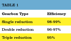
Table 1. The typical overall efficiencies of hydraulic pumps, as shown above, are simply the product of volumetric and mechanical/hydraulic efficiency.Source: Bosch Rexroth
Like theoretical flow, theoretical drive torque can be calculated. For the above pump, in SI units: 100 cc/rev x 207 bar / 20 x p = 329 Newton meters. But like actual flow, actual drive torque must be measured and this requires the use of a dynamometer. Not something we can - or need - to do in the field. For the purposes of this example though, assume the actual drive torque was 360 Nm. Mechanical efficiency would be 91% (329 / 360 x 100 = 91%).
Overall efficiency is simply the product of volumetric and mechanical/hydraulic efficiency. Continuing with the above example, the overall efficiency of the pump is 0.9 x 0.91 x 100 = 82%. Typical overall efficiencies for different types of hydraulic pumps are shown in the Table 1.
System designers use the pump manufacturers’ volumetric efficiency value to calculate the actual flow a pump of a given displacement, operating at a particular pressure, will deliver.
As already mentioned, volumetric efficiency is used in the field to assess the condition of a pump, based on the increase in internal leakage due to wear or damage.
When calculating volumetric efficiency based on actual flow testing, it’s important to be aware that the various leakage paths within the pump are usually constant. This means if pump flow is tested at less than full displacement (or maximum RPM) this will skew the calculated efficiency - unless leakage is treated as a constant and a necessary adjustment made.
For example, consider a variable displacement pump with a maximum flow rate of 100 liters/minute. If it was flow tested at full displacement and the measured flow rate was 90 liters/minute, the calculated volumetric efficiency would be 90 percent (90/100 x 100). But if the same pump was flow tested at the same pressure and oil temperature but at half displacement (50 L/min), the leakage losses would still be 10 liters/minute, and so the calculated volumetric efficiency would be 80 percent (40/50 x 100).
The second calculation is not actually wrong, but it requires qualification: this pump is 80 percent efficient at half displacement. Because the leakage losses of 10 liters/minute are nearly constant, the same pump tested under the same conditions will be 90 percent efficient at 100 percent displacement (100 L/min) - and 0 percent efficient at 10 percent displacement (10 L/min).
To help understand why pump leakage at a given pressure and temperature is virtually constant, think of the various leakage paths as fixed orifices. The rate of flow through an orifice is dependant on the diameter (and shape) of the orifice, the pressure drop across it and fluid viscosity. This means that if these variables remain constant, the rate of internal leakage remains constant, independent of the pump"s displacement or shaft speed.
Overall efficiency is used to calculate the drive power required by a pump at a given flow and pressure. For example, using the overall efficiencies from the table above, let us calculate the required drive power for an external gear pump and a bent axis piston pump at a flow of 90 liters/minute at 207 bar:
As you’d expect, the more efficient pump requires less drive power for the same output flow and pressure. With a little more math, we can quickly calculate the heat load of each pump:
No surprise that a system with gear pumps and motors requires a bigger heat exchanger than an equivalent (all other things equal) system comprising piston pumps and motors.

Hydraulic pumps convert mechanical energy into hydraulic energy. A high-performance piston pump can convert mechanical energy into hydraulic energy with an efficiency of 92 percent.
If the pump drives a piston motor, the motor is able to convert this hydraulic energy back into mechanical energy with an efficiency of 92 percent. The overall efficiency of this hydraulic drive, without considering flow losses, is 85 percent (0.92 x 0.92 x 100 = 85).
The inefficiencies or losses in a hydraulic drive can be divided into two categories: hydraulic-mechanical, which comprise flow and mechanical friction losses, and volumetric, which comprise leakage and compressibility losses (Figure 1).
The advantages of a hydraulic drive, which include high-power density (high-power output per unit mass), variable speed control, simple overload protection and both rotary and linear motion, are possible from a single system.
As Table 1 shows, a key disadvantage of a hydraulic drive is that it is far less efficient than a mechanical drive. What’s worse, the wear process decreases a hydraulic drive’s volumetric efficiency (and therefore total efficiency) causing the drive to slow down and more energy to be given up to heat.
The hydraulic pump is usually the hardest working component of a hydraulic system. As the pump wears in service, internal leakage increases and therefore the percentage of theoretical flow available to do useful work (volumetric efficiency) decreases. If volumetric efficiency falls below a level considered acceptable for the application, the pump will need to be overhauled.
In a condition-based maintenance environment, the decision to change-out the pump is often based on remaining bearing life or deterioration in volumetric efficiency, whichever occurs first.
Volumetric efficiency is the percentage of theoretical pump flow available to do useful work. In other words, it is a measure of a hydraulic pump’s volumetric losses through internal leakage and fluid compression. It is calculated by dividing the pump’s actual output in liters or gallons per minute by its theoretical output, expressed as a percentage. Actual output is determined using a flow-tester to load the pump and measure its flow rate.
Because internal leakage increases as operating pressure increases and fluid viscosity decreases, these variables should be included when stating volumetric efficiency. For example, a hydraulic pump with a theoretical output of 100 GPM, and an actual output of 94 GPM at 5,000 PSI and 46 cSt is said to have a volumetric efficiency of 94 percent at 5,000 PSI and 46 cSt.
In practice, fluid viscosity is established by noting the fluid temperature at which actual pump output is measured and reading the viscosity off the temperature/viscosity graph for the grade of fluid in the hydraulic system.
When calculating the volumetric efficiency of a variable displacement pump, internal leakage must be expressed as a constant. Consider this example: I was recently asked to give a second opinion on the condition of a large, variable displacement pump. My client had been advised that its volumetric efficiency was down to 80 percent and based on this advice, he was considering having the pump overhauled.
The hydraulic pump in question had a theoretical output of 1,000 liters per minute at full displacement and maximum rpm. Its actual output was 920 liters per minute at 4,350 PSI and 46 cSt. When I advised my client that the pump’s volumetric efficiency was in fact 92 percent he was alarmed by the conflicting assessments. To explain the disparity, I asked to see the first technician’s test report.
The technician had limited the pump’s displacement to give an output of 400 liters per minute (presumably the maximum capacity of his flow-tester) at maximum rpm and no load. At 4,350 PSI the recorded output was 320 liters per minute. From these results, volumetric efficiency had been calculated to be 80 percent (320/400 x 100 = 80).
To help understand why this interpretation is incorrect, think of the various leakage paths within a hydraulic pump as fixed orifices. The rate of flow through an orifice is dependent on the diameter (and shape) of the orifice, the pressure drop across it and fluid viscosity. This means that if these variables remain constant, the rate of internal leakage remains constant, independent of the pump’s displacement.
Note that in the above example, the internal leakage in both tests was 80 liters per minute. If the same test was conducted with pump displacement set to 100 liters per minute at no load, pump output would be 20 liters per minute at 4,350 PSI - all other things equal.
This means that this pump has a volumetric efficiency of 20 percent at 10 percent displacement, 80 percent at 40 percent displacement and 92 percent at 100 percent displacement. As you can see, if actual pump output is measured at less-than-full displacement (or maximum rpm), an adjustment needs to be made when calculating volumetric efficiency.
In considering whether it is necessary to have this hydraulic pump overhauled, the important number is volumetric efficiency at 100 percent displacement, which is within acceptable limits. If my client had based his decision on volumetric efficiency at 40 percent displacement, his company would have paid thousands of dollars for unnecessary repairs.

While it’s not usually possible to see inside a hydraulic pump and motor assembly and observe the wear taking place, there is one surefire clue that makes it possible to know if these important components are on their way out. Declining efficiency is a sign of leakage and/or increased internal friction, which is why keeping an eye on the efficiency of your pumps is a good way to monitor the health of your equipment. In this article, we’ll explore two aspects of hydraulic pump and motor efficiency and what they can tell you about what’s going on inside. Allowing you to repair and replace worn units in time to avoid costly failures.
Every new pump or motor has a specified ‘theoretical’ flow and torque rating. These are the numbers the unit should be able to achieve in a perfect world. However, the real world is never perfect and in reality, things like friction will mean that your actual performance will always be somewhere below the ideal theoretical number.
In addition, over the lifespan of the unit, various components such as bearings, pump elements, fluid, and other internals begin to deteriorate and as this happens, the pump gradually becomes less efficient. This deterioration can be measured in relation to the specified performance of the pump. This is useful to understand because it’s a clear indication of pump wear and gives us a valuable clue to alert us to repair or replace these units before its too late.
We can measure this loss of efficiency by looking at two aspects of efficiency, which are hydro-mechanical efficiency and volumetric efficiency. Each of these tells us something about the condition of the pump/motor and whether it is likely to fail in the near future.
In layman’s terms, Volumetric Efficiency refers to the amount of fluid a pump delivers and it is usually measured in litres per minute. In ideal conditions, a positive-displacement pump should deliver the same amount of liquid for each rotating cycle. As the unit wears, fluid slippage slowly increases and the amount of liquid delivered per cycle decreases. Thus, a decrease in volumetric efficiency indicates losses due to leakage or bypass. The decline in volumetric efficiency is accompanied by an increase in the cycle time of actuators such as hydraulic cylinders as the flow has been slowed. If the degradation is allowed to continue, the hydraulic system may become completely inoperable, requiring the repair or replacement of the worn pumps and motors to get up and running again.
The second category to look at is hydro-mechanical efficiency, which indicates the amount of fluid and mechanical friction within the system. To determine a motor’s hydro-mechanical efficiency, look at the actual torque output compared to the unit’s rated torque output. If a motor’s real-world output is 20% below its theoretical torque rating, then the motor can be said to be 80% efficient. A reduction in actual torque is, therefore, a sign that bearings and other mechanical internals are becoming worn and generating more friction.
Hydraulic pump and motor efficiency can have a significant effect on your hydraulic system. Inefficient components draw more power and drive up the running costs of your operation, so always a good idea to be aware of how your equipment is performing. However, declining efficiency is also an important way to monitor the health of your hydraulic pumps and motors. Warning signs such as slowing hydraulic actuators and loss of torque are a symptom of decreasing efficiency that – if left unchecked – will eventually lead to failure of hydraulic equipment. These components will eventually need to be repaired or replaced, but in the long term it’s more cost-effective to do so before they fail or start to inflate operating expenses.

600 gpm of water is pumped a head of 110 ft. The efficiency ofthe pump i s 60% (0.6) and the specific gravity of water is 1. The pump shaft power can be calculated as
The shaft power - the power required transferred from the motor to the shaft of the pump - depends on the efficiency of the pump and can be calculated as Ps(kW) = Ph(kW)/ η (3)

Knowing how to right-size an electric motor for your hydraulic pump can help reduce energy consumption and increase operational efficiency. The key is to ensure the pump motor is operating at peak continuous load. But how can you know how much power is needed?
Before you can choose the correct electric motor, you must know how much horsepower (Hp) is required to drive the pump shaft. Generally, this is calculated by multiplying the flow capacity in gallons per minute (GPM) by the pressure in pounds per square inch (PSI). You then divide the resulting number by 1714 times the efficiency of the pump, for a formula that looks like this:
If you’re not sure how efficient your hydraulic pump is, it is advisable to use a common efficiency of about 85% (Multiplying 1714 x 0.85 = 1460 or 1500 if you round up). This work-around simplifies the formula to:
The above formula works in most applications with one notable exception: If the operating pressure of a pump is very low, the overall efficiency will be much lower than 85%. That’s because overall efficiency is equal to mechanical efficiency (internal mechanical friction) plus volumetric efficiency.
Internal friction is generally a fixed value, but volumetric efficiency changes depending on the pressure used. Low-pressure pumps have high volumetric efficiency because they are less susceptible to internal leakage. However, as the pressure goes up and internal fluids pass over work surfaces such as pistons, port plates, and lubrication points, the volumetric efficiency goes down and the amount of torque required to turn the pump for developing pressure goes up.
This variance makes it very important to know the efficiency of your pump if you’re using it at low pressure! Calculations that do not take low pressure into account will lead to a failed design.
If you calculate 20 GPM @ 300 PSI with an assumed overall efficiency of 89%, you would probably select a 5 Hp electric motor. However, if you calculate the same 20 GPM @ 300 PSI with the actual overall efficiency of 50%, you would know that you should be using a 7.5 Hp motor. In this example, making an assumption about the efficiency of your pump could result in installing a motor that is too large, driving up your overall operating cost.
There are many contributors to the overall efficiency of a hydraulic pump, and it pays to be as accurate as possible when choosing a motor. A best practice for proper sizing is to use published data from the pump vendor that shows actual input torque vs. pressure or overall efficiency vs pressure. Note that efficiency is also affected by RPM.
Identifying a right-sized motor for your hydraulic pump does not always ensure you are using the most efficient motor. Be sure to read Part 2 of this post to learn how RMS loading and Hp limiting can help you scale down the size of your electric motor to save money while maximizing efficiency.

Editor"s Note: This is the first in a six-part series on centrifugal pump efficiency. For other articles in this series, clickCentrifugal Pump Efficiency series.
In this multi-part series, we will investigate several aspects of centrifugal pump efficiency. First, I will define efficiency and give some examples. Next, I will examine some of the design criteria that ultimately dictate the efficiency exhibited by a particular pump.
I will also try to make that somewhat nebulous quantity, known as specific speed, more meaningful. I will illustrate its effect on the shape of a pump’s performance curve and overall pump efficiency.
Next, I will explain the contributions of individual pump components to a pump’s overall efficiency and show why the combined efficiency of a pump and its driver is the product, not the average, of the two efficiencies.
How pump efficiency can be preserved by changing impeller speed rather than reducing it diameter will also be examined. Then I will compare the value of peak efficiency versus the breadth of efficiency over a range of flow. The discussion will end with the importance, or sometimes unimportance, of efficiency as it relates to a particular application or process.
When we speak of the efficiency of any machine, we are simply referring to how well it can convert one form of energy to another. If one unit of energy is supplied to a machine and its output, in the same units of measure, is one-half unit, its efficiency is 50 percent.
The efficiency of the typical automobile engine is around 20 percent. To put it another way, 80 percent of the heat energy in a gallon of gasoline does no useful work. Although gas mileage has increased somewhat over the years, that increase has as much to do with increased mechanical efficiency as increased engine efficiency itself.
In the pump industry, much of the work involves two extremely simple, yet efficient, machines—the centrifugal pump and the AC induction motor. The centrifugal pump converts mechanical energy into hydraulic energy (flow, velocity and pressure), and the AC motor converts electrical energy into mechanical energy.
Many medium and larger centrifugal pumps offer efficiencies of 75 to 93 percent and even the smaller ones usually fall into the 50 to 70 percent range. Large AC motors, on the other hand, approach an efficiency of 97 percent, and any motor—ten horsepower and above—can be designed to break the 90 percent barrier.
The overall efficiency of a centrifugal pump is simply the ratio of the water (output) power to the shaft (input) power and is illustrated by the equation below:
The constant (3,960) converts the product of flow and head (GPM-feet) into BHP. These equations predict that a pump that produces 100 GPM at 30 feet of head and requires 1 BHP will have an overall efficiency is 75.7 percent at that flow point. An extension of the second equation also allows the computation of the BHP required at any point on a pump’s performance curve if we know its hydraulic efficiency. I will show some examples of this later in this series.
The overall efficiency of a centrifugal pump is the product of three individual efficiencies—mechanical, volumetric and hydraulic. Mechanical efficiency includes losses in the bearing frame, stuffing box and mechanical seals. Volumetric efficiency includes losses due to leakage through the wear rings, balancing holes and vane clearances in the case of semi-open impellers. Hydraulic efficiency includes liquid friction and other losses in the volute and impeller.
Although mechanical and volumetric losses are important components, hydraulic efficiency is the largest factor. The centrifugal pump has a lot in common with the induction motor when it comes to the design phase. The commonality is that both have only two major components that can be modified by the designer. In the case of the motor, it is the rotor and the stator. For the centrifugal pump, it is the impeller and the volute (or diffuser). Let’s start our investigation of centrifugal pump efficiency with the impeller.
In the early days, that is exactly what pump designers did. Today, however, they can draw on years of experience and, at a minimum, find a suitable starting point for the design. That starting point is specific speed. Next month, we will investigate specific speed and how it can predict the performance of a particular impeller.
There are many great pump books available today, but one of the classics is now available as a free download at Google Books. Pumping Machinery was authored by Arthur M. Green, a professor of mechanical engineering at Rensselaer Polytechnic Institute and was published by John Wiley & Sons over 100 years ago. It begins with a comprehensive history of pumps and ends with a detailed review of centrifugal pumps and their advances over the previous twenty years. You will be impressed at the level of knowledge possessed by the author. The number of illustrations is amazing and accounts for a significant portion of its 725 pages. This one gets an A+ rating from me.

Imagine any type of pump; it has a driver to transfer the power to the pump shaft and a coupling, which connects the driver to the pump shaft. Outside the entrance of the pump structure, there is a bearing housing, which contains bearings to withstand applied forces to the pump shaft.
IMAGE 1: An ordinary centrifugal pump component. (1) - bearing housing; (2) sealing region; (3) - pump shaft; (4) - suction nozzle; (5) impeller; (6) - discharge nozzle; (7) - pump casing (Images courtesy of the author)
After we push the start button of the pump, the driver will run and start to transfer mechanical power to the pump shaft. As illustrated in image 2, between the driver and pump shaft there is a coupling, which incurs some loss of power.
So now, the pump shaft has received power from the driver, needs to transfer it directly to the impeller and finally send it to a pumping medium, but as mentioned before, there will be some losses on bearing housing and on the sealing area.
Now we can understand the scenario in which power absorbed by the impeller is less than the power produced by the driver. For power that is absorbed by the pump shaft, we will use “Pshaft,” and for power absorbed by the impeller, we will use “Pimpeller” as a symbol for calculations.
After this step, now let us raise the question: has all of P impeller been transferred to the pumping medium or not? To answer this question, we shall explain the second type of efficiency, which is hydraulic efficiency (ηhydraulic).
In Equation 4, we assumed that all the flow that enters the pump also exits from it. So in other words, Qinlet = Qoutlet. However, is this a true assumption?
This is definitely not true because inside of the pump, there are a lot of gaps, like the gap of the tip of an impeller with casing, the gap between wear rings, etc. Therefore, there is always some amount of leakage. This means that Qinlet > Qoutlet (Equation 5).

Focusing on high efficiency and high reliability when specifying a pump or pumping unit is essential to achieving the lowest total cost of ownership for an application.
As with any machine, a pump cannot be 100% efficient. However, pump reliability can approach 100%, but it requires specifying the correct pump for the application, strictly adhering to the manufacturers recommendations, and regularly monitoring and maintaining the pumping unit (pump, driver, and drive) and system components. Furthermore, pump efficiency and reliability are often intertwined. As pump efficiency decreases, the pump reliability often decreases as well, and vice versa. Let’s first examine efficiency.
Efficiency relates to energy consumption: energy output versus energy input. If two machines perform the exact same amount of work, the machine that consumes less energy to preform that work is more efficient. Efficiency is expressed as the ratio of power output divided by power input. For example, if a pumping unit consumes 25 kW of electrical power to produce 21 kW of pumping power, the unit is 84% efficient (21 kW ÷ 25 kW = 0.84 or 84%). But only a portion of the inefficiency can be attributed to the bare pump itself. The rest comes from mechanical and electrical losses in the motor and drive.
Because the combination of the pump and the electric motor driving it has the greatest effect on wire-to-liquid efficiency, selecting the correct and most efficient pump for the application often leaves little room for compromise. However, you usually have a wide choice of motors to drive a pump, and some will be more efficient than others.
Most pump drivers operate at a constant speed, but some applications are best served by variable speed (or variable frequency) drives. These systems use electronic controls to reduce the speed of the motor (and, therefore, the pump) to the required flow or pressure that the system demands. This can complicate the selection of the pump and motor because the motor runs more efficiently at one speed and percent torque load, whereas the pump may be more efficient at another speed or operating condition. The decision of selecting the pump and motor, then, requires careful study to match the pump, driver, and drive to the system requirements.
Regardless of whether the pump will run at a fixed or variable speed, if you choose to spend less money for a less-efficient motor you’ll pay the penalty of higher energy costs year after year for the life of the motor. The additional cost of energy to operate the pumping unit can cost hundreds—sometimes thousands—of dollars more each year in exchange for saving a few hundred dollars up front.
People often think of pump efficiency as mechanical efficiency. Again, pump efficiency is the ratio of power output to power input. If a pump has an efficiency of 87%, the 13% loss in efficiency is attributed to mechanical, volumetric, and hydraulic losses within the pump. Mechanical efficiency typically accounts for bearing, packing box, mechanical seal and all disk friction losses including wear rings, balancing disks or drums if present.
Hydraulic efficiency accounts for liquid friction losses in all through-flow passages including suction elbow or nozzle, impeller, diffuser vanes, volute casing and crossover passages of multistage pumps.
For example, centrifugal pumps are rated for a theoretical flow based on the pump’s speed, design, and fluid properties (viscosity, density, temperature, etc.). If a pump’s theoretical flow is rated at, say, 100 gpm, it’s actual flow may be 98 gpm. In this case, the pump’s volumetric efficiency would be 98%. The same procedure would apply for the hydraulic efficiency. If the theoretical output pressure of the pump is 50 psi and its actual output pressure is 44 psi, then the pump’s hydraulic efficiency would be 88%.
Pumps must be manufactured so that moving parts do not contact each other. Otherwise, friction between the contacting surfaces would wear rapidly and potential cause premature failure of the pump. Therefore, pumps are made with small clearances between moving parts, such as the gap between a centrifugal pumps impeller eye and its wear ring or volute casing. Without the clearance, the impeller would rub producing additional friction losses and potentially causing a premature failure.
These clearances provide a path for liquid to bypass the pumping chamber. So a small amount of fluid leaks back to the inlet area of the pump rather than out the discharge nozzle. This flow is referred to as internal leakage, a measure of volumetric inefficiency.
Pumps are usually most efficient when they are new, so pump efficiency tends to diminish with age. No surprise here. As a pump’s internal components become worn, efficiency decreases. Likewise with contamination. As dirt and other contaminants block passageways or become trapped between moving parts, the pump can become less efficient.
Efficiency is a key parameter when selecting a pump, but equally important is reliability. Just because a pump has a high best efficiency point (BEP) doesn’t mean it’s reliable. Likewise, a pump can be reliable without being the most efficient. If a pump is chosen for an application based solely on BEP efficiency, the cost of energy to operate the pump might be lower over time, but the higher operating cost of the unreliable pump can incur downtime and maintenance costs that far exceed any savings from low energy consumption.
Selection of the pump and motor for the application—Pumping units must be specified not only for the fluid being pumped at the required pressures and flow rates, but to be compatible with the surrounding environment. Likewise, the electric motor must be powerful enough to drive the pump at the required speed and deliver the required torque.
Proper installation and startup—As with any rotating machinery, pumps must be securely installed and in proper alignment with the driver and mating components. These components include the foundation, suction piping, discharge piping, and certain accessories. Startup procedures must adhere to manufacturers’ recommendations for pumps, motors, and other components that make up the pumping unit.
Correct operation and flow control—Manufacturers’ recommendations must also be followed regarding operating parameters (minimum flow, perforable operating range (POR), allowable operating range (AOR), and minimal continuous stable flow). In addition, operating the pump at the correct speed is critical because it can have a profound effect on flow, pressure, and power consumption. For example, it’s often preferred to specify variable-speed operation rather than fixed-speed operation to drive a pump. That’s because fixed speed operation drives the pump at one continuous speed and uses throttling valves to increase system losses to achieve different flowrates or pressures required by the application.
This approach typically reduces energy efficiency because the pump draws full speed power at a lower pump efficiency even though the application requires only a portion of total flow. A variable-speed drive, however, would place the operating condition at a higher efficiency point on the pump curve allowing the pump to be more energy efficient and more reliable. Nevertheless, depending on the type of pump and application requirements, a variable-speed drive may not be required or may not be the best choice.
Proper maintenance—As with any industrial machine, maintenance is the key to reliable operation. Even if everything discussed thus far has been executed to perfection, incorrect or negligent maintenance will eventually lead to component or even complete pump or system failure. Proper maintenance goes beyond repairing a malfunction once it occurs and should include preventive maintenance.
Monitoring operation and history—The next level is predictive maintenance, which relies on collecting data on key variables over time. This data may include condition monitoring of pressures, flows, vibration, and other parameters of key components. For example, a pump produces a baseline vibration signature or housing temperature when it is commissioned. Monitoring the vibration and temperature over time can give an advance warning of an impending failure if either value increases suddenly or reaches a threshold value over time. This provides a reliable method of predicting that failure is about to occur. Shutting down the system at an opportune time to inspect and correct the condition, then, prevents a catastrophic failure.
Failure in any of these areas usually results in equipment failure and unscheduled downtime. The only way to ensure that all of these conditions are executed properly and at the right time is establish a pump management program. Doing so will maximize the reliability and efficiency of the pumping system.

Pumps tend to be one of the biggest energy consumers in industrial operations. Pump motors, specifically, require a lot of energy. For instance, a 2500 HP triplex pump used for frac jobs can consume almost 2000 kW of power, meaning a full day of fracking can cost several thousand dollars in energy costs alone!
So, naturally, operators should want to maximize energy efficiency to get the most for their money. Even a 1% improvement in efficiency can decrease annual pumping costs by tens of thousands of dollars. The payoff is worth the effort. And if you want to remotely control your pumps, you want to keep efficiency in mind.
In this post, we’ll point you in the right direction and discuss all things related to pump efficiency. We’ll conclude with several tips for how you can maintain pumping efficiency and keep your energy costs down as much as possible.
In simple terms, pump efficiency refers to the ratio of power out to power in. It’s the mechanical power input at the pump shaft, measured in horsepower (HP), compared to the hydraulic power of the liquid output, also measured in HP. For instance, if a pump requires 1000 HP to operate and produces 800 HP of hydraulic power, it would have an efficiency of 80%.
Remember: pumps have to be driven by something, i.e., an electric or diesel motor. True pump system efficiency needs to factor in the efficiency of both the motor AND the pump.
Consequently, we need to think about how electrical power (when using electric motors) or heat power (when using combustion engines) converts into liquid power to really understand pump efficiency.
Good pump efficiency depends, of course, on pump type and size. High-quality pumps that are well-maintained can achieve efficiencies of 90% or higher, while smaller pumps tend to be less efficient. In general, if you take good care of your pumps, you should be able to achieve 70-90% pump efficiency.
Motor efficiency is also an important factor here. Motor efficiency depends on the fuel type, whether electricity or hydrocarbon, which in turn depends on availability and cost.
AC motors can achieve 90%+ efficiency when converting electrical to mechanical energy. Combustion engines are much less efficient, with typical efficiency ratings coming in at ~20% for gasoline and ~40% for diesel. Your choice of engine or motor type will depend on the availability and cost of fuel or electricity in your area.
Now that we have a better understanding of the pump efficiency metric, let’s talk about how to calculate it. The mechanical power of the pump, or the input power, is a property of the pump itself and will be documented during the pump setup. The output power, or hydraulic power, is calculated as the liquid flow rate multiplied by the "total head" of the system.
Remember: we’re trying to find the ratio of power in to power out. Since rations require equal units on both sides, we"ll have to do some conversions to get our hydraulic power units in HP. You"ll see how this is done in the example below.
IMPORTANT: to calculate true head, you also need to factor in the work the pump does to move fluid from the source. For example, if the source water is below the pump, you need to account for the extra work the pump puts in to draw source water upwards.
*Note - this calculation assumes the pump inlet is not pressurized and that friction losses are minimal. If the pump experiences a non-zero suction pressure, or if there is significant friction caused by the distance or material of the pipe, these should be factored in as well.
You"ll notice that the elevation head is minimal compared to the discharge pressure, and has minimal effect on the efficiency of the pump. As the elevation change increases or the discharge pressure decreases, however, elevation change will have a greater impact on total head.
Obviously, that’s a fair amount of math to get at the pump efficiency, considering all of the units conversions that need to be done. To avoid doing these calculations manually, feel free to use our simple pump efficiency calculator.
Our calculations use static variables (pump-rated horsepower and water source elevation) and dynamic variables (discharge flow and pressure). To determine pump efficiency, we need to measure the static variables only once, unless they change.
If you want to measure the true efficiency of your pump, taking energy consumption into account, you could add an electrical meter. Your meter should consist of a current transducer and voltage monitor (if using DC) for electrical motors or a fuel gauge for combustion. This would give you a true understanding of how pump efficiency affects energy consumption, and ultimately your bank account.
Up until this point, we’ve covered the ins and outs of how to determine pump efficiency. We’re now ready for the exciting stuff - how to improve pump efficiency!
One of the easiest ways to improve pump efficiency is to actually monitor pumps for signs of efficiency loss! If you monitor flow rate and discharge (output power) along with motor current or fuel consumption, you’ll notice efficiency losses as soon as they occur. Simply having pump efficiency information on hand empowers you to take action.
Another way to increase efficiency is to keep pumps well-maintained. Efficiency losses mostly come from mechanical defects in pumps, e.g., friction, leakages, and component failures. You can mitigate these issues through regular maintenance that keeps parts in working order and reveals impending failures. Of course, if you are continuously monitoring your pumps for efficiency drops, you’ll know exactly when maintenance is due.
You can also improve pump efficiency by keeping pumps lubricated at all times. Lubrication is the enemy of friction, which is the enemy of efficiency (“the enemy of my enemy is my friend…”).
A fourth way to enhance pump efficiency is to ensure your pumps and piping are sized properly for your infrastructure. Although we’re bringing this up last, it’s really the first step in any pumping operation. If your pumps and piping don’t match, no amount of lubricant or maintenance will help.
Pipes have physical limits to how much fluid they can move at a particular pressure. If pipes aren’t sized properly, you’ll lose efficiency because your motor will have to work harder. It’s like air conditioning - if your ductwork isn’t sized appropriately for your home, you’ll end up paying more on your energy bill.
In this post, we’ve given you the full rundown when it comes to calculating and improving pump efficiency. You can now calculate, measure, and improve pump efficiency, potentially saving your business thousands of dollars annually on energy costs.
For those just getting started with pump optimization, we offer purpose-built, prepackaged solutions that will have you monitoring pump efficiency in minutes, even in hazardous environments.

?I just love this newsletter. As a Hydraulics Instructor for Eaton, I make copies and distribute them to my students as I address various topics. Please keep "em coming.?
A hydraulic pump can be defined as a mechanical power source which converts mechanical power into hydraulic energy. Hydraulic pumps are typically used for hydraulic drive systems. The way it works is by generating flow with sufficient power capable of overcoming the pressure created from the pump outlet’s load. When in operation, a hydraulic pump generated a vacuum right at the pump inlet, and that forces liquid to move via an inlet line into the pump from the reservoir.
Hydraulic gear pumps that typically come with outer teeth are economically simple pumps. While they have a swept displacement or volume range between 1 to 200 mm, they tend to have the lowest volumetric efficiency of all pump types.
Rotary vane pumps, both simple adjustable and fixed displacement tend to have higher efficiency compared to gear pumps, however, they are functional for mid range pressures (180bar). Units made today can withstand pressures more than 300bar during continuous operation.
Screw pumps are made of 2 Archimedes’ screws which intermesh and closed into a single chamber. Screw pumps are suitable for high flows with low pressures of around 100bars. Screw pumps are mainly used because they generate little to no noise, however they are not that efficient.
Piston pumps make use of a swashplate principle to devices both adjustable and fixed displacement. This gives them the design advantage of being compact. These pumps are much more economical and easier to make, however, one disadvantage is that they do become prone to contamination by oil. Axial piston pumps are known to be the most used variable displacement type, as it has been found in nearly everything from mobile to heavy industrial applications.
A hydraulic motor can be defined as a mechanical actuator which transforms hydraulic flow and pressure into angular displacement and torque. A hydraulic motor is the movable piece of a hydraulic cylinder. In a broader sense, devices known as hydraulic motors sometimes include those that are able to run in hydropower, however, this term has been refined to define only motored that make use of hydraulic fluid as a portion of their closed hydraulic circuits.
To avoid any unnecessary and frustrating breakdowns, it is important to keep your machinery well maintained. With regular preventative maintenance you will be able to spot any developing problems and have them repaired quickly and efficiently by CJ Plant, before any further, more severe, and expensive damage occurs. Below are some key steps to prioritise when maintaining your hydraulic motor.
Pressure and flow make up the foundation of hydraulic operation. Consistent testing of these measures will provide a good indication of the overall health of your hydraulic motor. Changes in either level will generally suggest a bigger problem that could range from leaking seals to contaminated hydraulic fluid.
Taking samples of the hydraulic fluid or oil from several points on the motor is very important. You should take more than one, as a single sample might not show contamination that occurs further in the system. Compare multiple samples to each other for both viscosity and integrity. Look out for if the fluid appears to thicken, thin, or become contaminated anywhere in the system.
Mark the normal fluid levels on the reservoirs and label each one with the type of fluid to use. If you mix or use the wrong type of fluid, you could contaminate the system and result in it becoming damaged. You should empty the reservoir, clean it, and refill it with fresh fluid on a schedule dictated by the manufacturer’s recommendations. Pay close attention to contaminated fluid and flush the entire system if the hydraulic liquid looks dirty.
Remove and clean key components of the hydraulic system including filters, couplers, gauges and more. Replace any of these that seem damaged or have excessive build up on them. Also, be sure that each junction of the system moves as expected.
Regular maintenance should include the draining and flushing of valves in the hydraulic system. After cleaning these points, test the valves and actuators in operation. Look for signs of any inefficient function, which could suggest a growing issue. Repair the problem to restore to full operation of the hydraulic motor and reduce the risk of it breaking down completely.
Right from the definition of these two types of hydraulic components, you can tell that they are different. In essence, Hydraulic pumps as components absorb mechanical kinetic energy to create hydraulic energy, while hydraulic motored do exactly the opposite.
While a hydraulic pump is connected to a prime mover, with the pump shaft with no extra radial load, the hydraulic motor is connected to the load via pulleys, sprockets and gears, so its main shaft can bear an increased radial load.
A hydraulic pump typically has a vacuum in its low pressure chamber. To ensure that it is able to be more efficient at oil absorption and anti-cavitation capability, its suction nozzle is typically larger than its nozzle for high pressure, however a hydraulic motor does not require any of these.
Hydraulic motors typically need negative and positive rotation, which then causes the motor’s internal structure to be symmetrical. Whereas hydraulic pumps usually rotate in a single direction, which negates the need for such a requirement. For instance, a vane motor’s blades have to be arranged radially, unlike the incline of a vane pump, else the blades could become broken when they reverse. An axial plunger motor needs its distribution plate to be symmetrical in design, however an axial plunger pump does not. This is the same for a gear motor as it has to have a unique leakage tube, which cannot be directly connected into the low pressure chamber as a gear pump would.
A hydraulic motor has a vastly wider speed range which means it is able to switch from lubrication mode to hearing form. A hydraulic motor requires a low minimum stable speed, and certain hydraulic motors also require variable brake and speed.
Hydraulic motors require a large amount of start up torque, so as to be able to overcome the static friction encountered during start-up. They also require enough start-up torque when there is a case of pressure fluctuation. For example, for internal friction to be reduced in a hydraulic motor, the amount of teeth a gear motor has is increased, and an axial clearance compensation device with a smaller compression coefficient than that of a pump is introduced.
Hydraulic pumps have to be integrally self-priming. This is one of the reasons why point contact plunger motors can’t be used as pumps as they do not have the self-priming capability.
A vane pump’s blade is pushed out due to centrifugal force and that creates a working chamber. If this pump is used as a motor, it will not function as the blade is not able to create the external force required of a working chamber when it starts.
For friction to reduce, version plunger motors eradicate slipper to become point contact motors, whereas plunger pumps are unable to function without slippers.
A hydraulic motor has a larger internal leakage, compared to the hydraulic pump. The reason for this is because a hydraulic motor’s leakage direction points in the same way as its motion and that results in motion speed becoming involved.
If you’re looking to get your hydraulic pumps or hydraulic motors repaired, why not contact the experts in hydraulic repairs at CJ Plant on 01527 535 804

Studies reveal that efficiencies of industrial hydraulic systems range from <9% to 60% efficient, and average efficiency was 22%. So on average, the cost of wasted energy is $24.3 billion. Improving efficiency of industrial hydraulics by just an additional 10% would result in savings of approximately $3 billion per year.
Efficiency is the ratio of output power to input power. For example, if a hydraulic components and system can transmit 100 hp out for some work process, but because of inefficiencies in the system it requires 125 hp of input from a prime mover, then the hydraulic system is 80% efficient.
The good news is there are many opportunities to improve efficiency and garner substantial energy and cost savings. Start with an understanding of the system operation and by reviewing schematics. Ask yourself, what areas are inefficient in their use of energy during operation? The key is analyzing the design’s required output power versus input power.
Reservoirs. Beware of rules of thumb that result in sizing the reservoir too large. Standard practice is three times the pump flow. But the primary reason given is to remove heat, which is a myth. The reservoir is not an effective heat sink and requires an extremely large size to dissipate typical heat, unless duty cycle is low.
Prime movers. Review the current electric-motor design and decide if the return on investment for energy savings would justify replacing the current unit with a premium high-efficiency motor. And it may be better for overall operation of the system to retrofit with a variable-speed drive. Except for applications where the pump-motor combination runs continuously at a constant speed, a VFD can often quickly pay for itself with sizable energy savings.
The Energy Independence and Security Act of 2007 (EISA) raised to a premium level the mandatory minimum nominal full-load efficiency for general-purpose motors rated below 1,000 V and up to 200 hp. For example, the previous standard efficiency for a 10 hp motor was 86.7% and the new minimum efficiency level is 92.2%. Minimum efficiency for motors greater than 200 hp is 96%. However, keep in mind that a 1% increase in efficiency for a 100 hp motor will result in more cost savings than a 9% increase in efficiency of a 10 hp motor.
The flow source (pump).Depending on the design and operation, efficiency can vary significantly from one type of pump to another. Analyze the overall efficiency of the hydraulic pump and the control method used, and evaluate your ROI to determine if it is justified to change to a more-efficient system.
Analyze dwell times, if any exist, and determine how to minimize energy use during this time. Among the possibilities: add an accumulator, unload the pump, select a variable-speed drive, or upgrade the pump controls. Using RMS power calculations helps determine if the prime mover can be downsized, which will reduce overall energy consumption during dwell times. Also, analyze pump displacement and determine if it is properly sized for the energy demand.
Evaluate the fluid.Determine fluid requirements, for example the viscosity, based on the application and system components. Two areas that primarily impact pumps and motors are volumetric efficiency and hydromechanical efficiency. There is a viscosity range where fluid friction, mechanical friction and volumetric losses are minimized and optimal for hydraulic system performance. This is the viscosity range where the hydraulic system will operate most efficiently — the highest ratio of output power to input power.
A study published in Machinery Lubrication magazine showed that by using high Viscosity Index fluids, typical cost savings per vane pump in mobile hydraulic systems was approximately $400 per year. Mobil Corp. conducted a study on a typical ISO VG 46 fluid versus a high VI fluid at the same viscosity grade and showed efficiency improvements of 3 to 6% due to the fluid alone.
Fluid conductor sizing.Pressure drop caused by frictional losses in fluid conductors is a significant source of wasted energy in a typical hydraulic system. Designers attempt to balance pressure drop against the cost of conductors and, in most cases, reduce the size of conductors to lower initial system cost without regard to total operating cost due to wasted energy.
So circuit designers should avoid extra fittings, sharp bends and undersized inner diameters of conductors — especially for pump inlets to avoid cavitation. In the pump inlet line, it is recommended that a straight length of at least 10 times the inner diameter of the fluid conductor be established directly prior to the pump inlet to allow for a transition back to laminar flow and minimize potential cavitation.
Undersized valves can also lead to increased energy loss due to throttling effects and friction (heat). Improperly sized pressure controls can have excessive pressure override which also results in energy waste and reduces efficiency.
Contamination control. To ensure a high-performing and reliable hydraulic system, engineers should determine the target cleanliness level, evaluate the contamination control system, and sample fluid regularly and look for evidence of oxidation.
Proper filtration and contamination control is essential for energy efficient systems. Improper contamination control leads to many consequences, none of them good. It results in increased component wear, with more internal leakage and wasted energy. It changes fluid viscosity which impacts efficiency as described previously.
Heat is also a contaminant, as it accelerates degradation (oxidation) of the fluid and impacts system efficiency. Lack of contamination control can result in valves partially opening and increasing throttling losses. Likewise, excessive air is another contaminant in the fluid, and it can affect heat transfer rates and damage pumps.
Actuator selection. Evaluate seal choice because internal friction results in energy loss. Different materials, types and designs can have a noticeable impact on dynamic seal performance and efficiency. Also evaluate the condition of internal seals, as damaged seals permit leakage which generates heat and wastes energy.


 8613371530291