
wd45 hydraulic pump adjustment supplier
There was nothing better to to on a rainy day in southern Illinois so my brother and I began working on the pump. We adjusted all the linkage according to the manual and with plenty of fluid it would only put out about 1500 psi at the remote outlet instead of the 3500. We pulled the pump off. It took quite allot of wiggling and cussing to get it out from between the frame rail and the housing!!! Got it out and laid on the work bench. All four cam followers still seemed to be spring loaded. The adjusting screw seemed to still move the control valve but not certain. We got this far, can our orange friends guide us further into this project?? Thanks, Ryan
To adj the pressure, remove the 4 -1/4 in bolts on front of pump holding plate on. There will be two valves exposed. Tap quick and lightly on the one closest to pumping plungers. It should bounce out farenough to get ahold of. Pull it out easy to keep every thing togather. There will be shims between spring and plunger. Add shims to increase pressure.
On spool opposite the pressure spool, drive the spool assy. to back of pump and replace the two orings along with two orings on pressure spool (unloading valve).
Just take your time and pay attention to detail.It"s not as intimidating as you think and you really can"t mess up much.I"d say keeping track of the direction and order of the control vavles and sleeves would be the most critical if you remove them.Mack"s advise had you leaving them in and alone.If it"s pumping good they are are not your problem as far as pressure goes.Sometimes they can get tiny bits of FM in them that don"t let them shift position which controls pump flow rate.Let"s say you tear it all apart and don"t have a clue how to put back.Put all the pieces in a box and take it to someone who knows these old units and they can whip it back together in short order.It ain"t really that high tech.
Do you have a transport valve on that tractor? My pump quit suddenly one spring and wouldn"t lift the disc. I found the shoulder on the relief spool had cracked and broke completely off letting the pump bypass continually. If you get a little piece of gunk on the ball or seat behind the relief spool it could be leaking by.
Ryan, Don"t be intimidated by working on the hyd pump. Just keep all the parts in order as they are removed. Keep the parts in clean diesel oil so they will not enlarge. Be sure to clean the pump. As said above it does not take much to foul up action.
Looks like you have gotten the pump working as suggested. However you do not have pressure Could be a leak somewhere. O-rings ect. Check spring pressure to be certain there are no broken springs. Are all the plungers moving well. Pull them out and see if there are any broken springs under them. Look closely.
Charlie, we were told from the factor to batter the end of nails to make tools to hold the cam followers in. If the pump does not come out easily then go to lunch. I did that came back and it almost fell out.
I"m thinking maybe all 45"s had transports but not sure. On the "nail" tip,you"ll see where to wedge them in the lever when you compress it down by hand.Once you"ve cleared the housing with the rollers and the pump is kinda hanging on the pickup tube,you can pull them out with pliers easily.Don"t drop one inside housing!
The thumbscrew on front adjusts amount of oil pumped.It should be out against the clutch hsg when pump is mounted.Some suggest screwing all in then out to fix a stuck valve if pump seems slow. Screw it in 1/2 for mounting pump then back it out(more clearence).Your pressure problem isn"t affected by this side of pump.Edited by Steve M C/IL - 24 Apr 2011 at 11:06pm
It still aint right!! We took pump off and very carefully started our rebuild. Ordered a seal and plunger kit from Agco part#70255272. All control valves were not stuck and were oiled and correctly reinstalled. All springs were not broken but replaced anyway. The only issue was the unloading valve assembly which Agco told me was no longer available but had a outside supplier. After all linkage was adjusted the pump was just as weak as before we started. It only would put out 1500psi and would slowly drop!! What are we missing?? The unloading valve from the after market supplier or what?? I don"t know whats left to work on. Ryan
Did the pump work OK say last year? You could add about .020 inch of shim to add about 1400psi but if it worked before and has recently lost pressure or volume, there is something wrong with the pump.
My new one from agco, several years ago wasn"t machined complete and caused my pump to unload at over 9000psi. I took it back apart and found a 1/4 inch diameter c"bore missing down inside the back end. That was like adding a 1/4 inch shim to the front.Edited by CTuckerNWIL - 28 May 2011 at 9:51pm
Years ago I put a new unloader in my 45 and it didn"t help a bit.Had 11 shims and still eradic unload pressures.Doubt unloader is culprit but this seems to be the $64000 question no one can answer.I"ve got a 5/16 washer with the center trimmed out as an additional shim and it"s useable.Always good pressure at/off idle but not at half throttle or more.Always suspected the check ball on back end of pump where it transfers to control valve of not holding and getting a "bounce back" of pressure which effects unloader but never went to the trouble to prove it.They didn"t include that "valve" in my rebuild kit from AC years ago.It takes pressure on the outlet end of unloader to lift ball off seat.I don"t understand how mine can vary so much but it"s most effected by rpm.I quit beating my head on the wall on got it useable and quit.
I think thats our next step. We have became real good at removing the pump!! What about the shim issue?? We are reading about 1500psi right now, now many shims would a person add?? Ryan

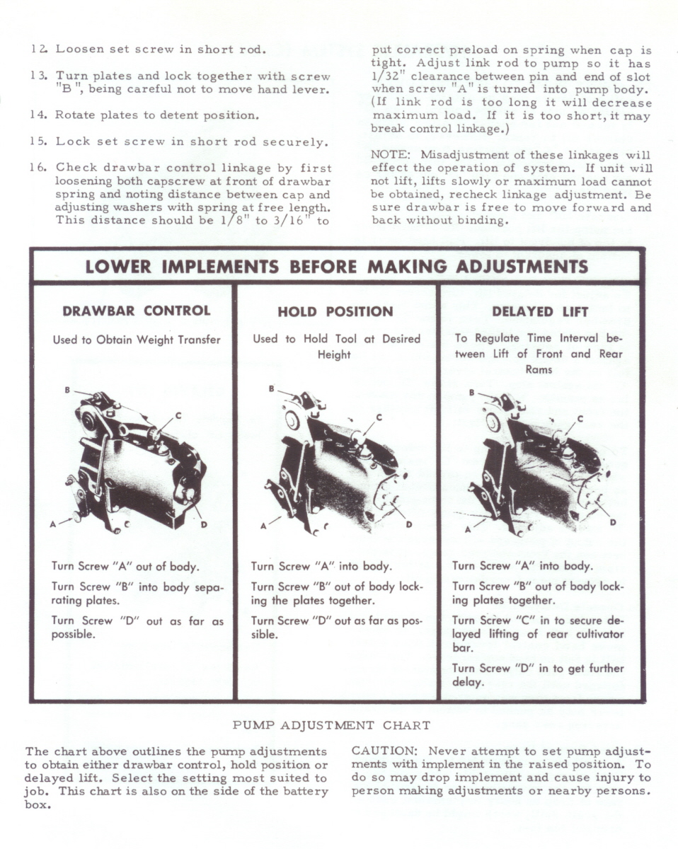
If you have a 4 to 6" diameter pulley on the pump, the easiest way to increase speed of response would be to reduce the diameter of this pulley. Since your pump is rated at 4000 rpm, you would be able to get close to this at full throttle with a 3" pulley. If all you see in the system is the 2 spool control valve, you may not have a pressure relief valve. Or there may be one in the pump. I"ll check the information at the web site that you gave us.
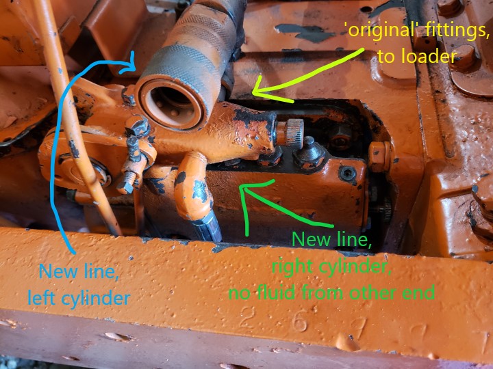
If your loader is Allis Chalmers, you can use the Allis hydraulics for your bucket but you will loose independent hydraulics and have complications with your lift arms. If the loader is not Allis Chalmers, the cylinders may work but the seals may blow as most cylinders are not rated at the pressures that Allis uses.
So, it is sort of a dance. If you go to a smaller pulley, you increase tendency to slip but you increase the volume and speed of the cylinders. You could go to a bigger pump and use a larger diameter pulley which would reduce the tension on the belt.
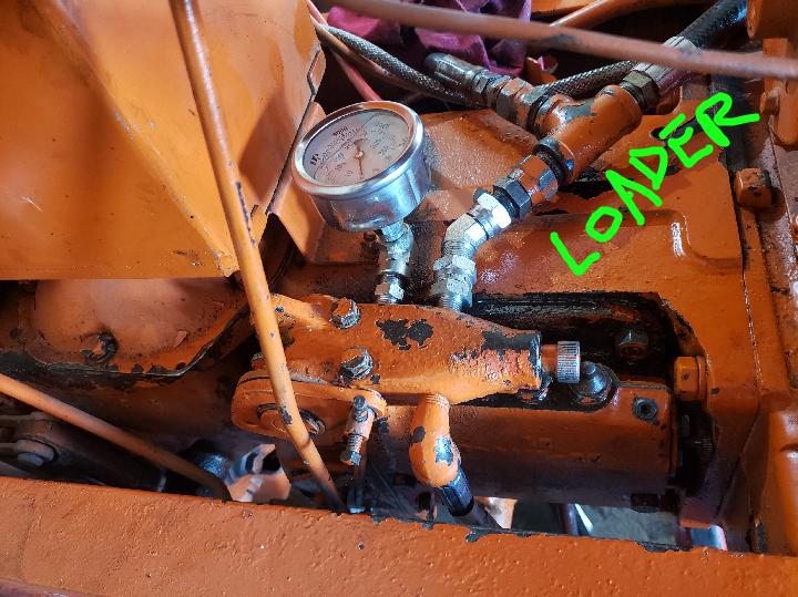
Can anyone tell me how to somehow convert the single hydraulic to a functioning 2 hose hookup...is there a bypass/throw valve that will allow this to work or....how much of a trouble is it to get this to work..t.i.a.
SHOP MANUAL ALLIS-CHALMERS Models B-C-CA-G tractor serial stamped on top of transmission. Models RC-WC-WF tractor serial stamped rear face of rear axle housing. Models WD-WD45 tractor serial stamped rear face of transmission. Model WD45 Diesel tractor serial number is located at left brake cover or on left rear side of transmission housing. B-C-CA-RC engine serial stamped on top of left rear engine flange. G engine serial stamped on side of left rear engine flange. WC-WD-WD45-WD45 Diesel-WF engine stamped on left side of cylinder block.
BUILT IN THESE VERSIONS Tricycle Type Axle Type Tractor Single Double Non- Adiust- Model Wheel Wheel Adjustable able B No No Yes YM C Yes Yes No YM CA YM YM No YM G No No No YM RC YM Yes No No we YM Yes Yes YM WD YM Yes No YM WD45 Yes Yes No YM WF No No YM No WD45D Y M Yes No YM
BELT PULLEY 311 311 308 310 310 310 310BRAKES Adjustment 300 301 304 305 305 306 306 Drums R & R 300 303 304B 277 277 282 282 R ^ n e ...".*.*.*.*.**.. 300 302 304 A 305A 305A 306A 306 ACARBURETOR {Not LP-Gas) 110 110 110 110 HO HO LP-Gas 1"CLUTCH Engine clutch 160 160 164 166 166 174 174 Engine clutch shait 215 ^ Final drive clutch 284 Transmission clutch 1"9 1"9COOLING SYSTEM Fan 133 133 132 133 134 134 Pump*".;".".!".".".". 135 135 135 135 135 158 Radiator 130 130 131 130 130 130 156DIESEL FUEL SYSTEM Energy Cells 154 Fuel Filters ^ 1*"A Injection Pump " *50 Nozzles 1*° Preheater •. "5 Quick Checks . 147DIFFERENTIAL Adjustment 240 240 242 245 247 250 250 R&R and overhaul 241 241 243 246 249 251 251ELECTRICAL 139 139 139 139 139 139 159
INDEX Cont. MODELS B-C CA G RC WCWF WD,WD45 WD45 ENGINE Diesel Assembly R&R 60 60 62,65 63 64 64 141 Cam followers 73 73 74 73 73 73 142D Camshaft 85 85 86 85 87 87 144 Connecting rods & bearings 95 95 96 95 95 95,95A 145B Crankshaft & bearings 97 97 98 97 97 97 145C Cylinder head 66 66 67 66 66 66 142 Cylinder s l e e v e s 91 91 91 91 91 144C Flywheel 1O3 103 103 103 103 103 146A Front oil seal 102 102 102 102 102 102 143B Main bearings 97 97 98 97 97 97 145C Oil pan 105 105 105 105 105 105 146 Oil pump 106 106 107 106 108 108 146B Pistons 91 91 92 91 91 91 144C Piston pins 93 93 94 93 93 93 145A Piston & rod removal 88 88 89 88 90 90 144B Piston rings 91 91 92 91 91 91 144C Rear oil seal 99 99 JOO 99 101 101 Rocker arms 75 75 145D 75 75 75 143 Tappets 73 73 74 73 73 73 Timing gear cover 78 78 79 142D 80 80 80 143B Timing gears 82 82 83 82 84 84 Valve guides 70 70 71 143C 70 70 70 142B Valves & valve seats. 68 68 69 68 68 68 Valve springs 72 72 72 142/. 72 72 72 142C Valve timing 73 76 77 76 76 76 143A FINAL DRIVE Axle housings 286 246 249 Bevel gears renew 253B 254B 255B 256B 257B 258B 258B Bevel gears adjust. 253 254 255 256 257 258 258 Bull gear renew 266 271 276 276 280 280 Bull pinion bearings adjust .. 267 272 281 281 Bull pinion renew 268 273 277 277 282 Differential overhaul 241 241 243 282 246 249 25; 251 Drive units overhaul 285 270 275 275 279 ^Wheel axle shafts 266 271 286 279 276 276 280 280FRONT SYSTEM Front axle member 5 5 5 5 5 5 Front steering gear 1 i 2 2 2 Main steering, Gemmer IS Main steering, Lavine 26 Main steering. Ross 22 22 22 22 Pedestal, adjust 1 1 2 2 2 Pedestal, overhaul 3 3 2 Pivot pin 10 11 12 4 4 4 4 13 13,14 11 11GOVERNOR Adjustment 115 us 117 115 119 119 153A Overhaul ne ng na 116 120 120IGNITION SYSTEM Battery Ignition Timing 140A HOB 140A Magneto Ignition Timing 140 140 140 140 140LIFT SYSTEM Linkage 33O 334 334 Pump 320 324 328 324 324 Testing 322 325 328 325 325 Trouble shooting 322 326 326 326 Work cylinder 329 329 329 329 329 Mechanical Type 340 340POWER TAKE-OFF 3U 311 314 314 314 3UREAR AXLE Refer to Final DriveSTEERING GEAR Refer to Front SystemTORQUE TUBE 185 185 186 186 190 190 WD WD Prior After Ser.TRANSMISSION Ser. 127007, 127008 W D 4 5 Assembly R&R 2OS 223 223 Beisic procedure 205 213 231 238 238 Bevel pinion 203 209 222 230 237 237 256B 257B 234 239B 239B Clutch shaft 215 226 226 Countershaft 203 228 228 235 Extra low gears ", 218 239C 239C Input shaft 202 208 220 226 Main shaft 202 208 220 226 233 239A 239A 227 227 Reverse idler 204 212 221 229 Shiiter forks 201 207 214 229 236 239D 239D 225 225 232 239 239 www.classicmachinery.net
CONDENSED SERVICE DATA (WD 45 Diesel) GENERAL TUNE
MODEL WD45 DIESEL www.classicmachinery.net
CONDENSED SERVICE DATA (All Non-Diesel Models) TRACTOR MODEL B (S£ B-C weGENERAL •""^^o) CA RC WF WD WD45 Engine Make Own Own Own Own Own Cont"L Own Engine Model BE CE N62 WD45 Cylinders 4 4 4 4 4 4 4 Bore—Inches 3V4 3% 4 4 2% 4 Stroke—Inch€JS 3 V4 4 4 4.5 Displacement—Cubic Inches 116 125 125 201 201 62 226 Compression Ratio Non LP-Gas 4.92 6.2 5.75 5.5 5.75 6.5 645 Compression Ratio Non LP-Gas 4.67 5.75 5.0, 5.5 5.4 5.25 Compression Ratio Non LP-Gas 5.2, 4.7 4.5. 6.6 4.75 Compression Ratio LP-Gas 7.2 Pistons Removed From: Above Above Above Above Above Below (3) Above Main Bearingir, Number of 3 3 3 3 3 2 3 Main Bearingii, Adjustable? (1) (1) (1) (1) (1) No (1) Rod Bearings, Adjustable? (1) (1) (1) (1) (1) No (4) Cylinder Sleeires Wet Wet Wot Wet Wet None Wot Forward Speeds 3 * 4 4 4 3 4 Generator & Starter Make D-R D-R D-R D-R D-R D-R •Band C - 3 speeds. CA - 4 speeds. D-RTUNE UP Firing Order 1, 2, 4, 3 1,2,4,3 1,2,4,3 1,2.4,3 1,2,4,3 1.3.4.2 h 2, 4, 3 Valve Tappet Gap OIOH B&C.OIOH .OIOH .012H .012H .012C .012H CA .012H Valve Seat and Face Angle 45 45 45 45 45 45 45 Ignition Distri butor Make None D-R None None D-R D-R D-R Ignition Distributor Model 1H1735 11H745 1111708 1111745 Ignition Magneto Make F-M F-M F-M F-M F-M Nono None Breaker Gap 020 .020 .020 .020 .020 .020 .020 Magneto Lag Angle 30* 30*" 30*" 30" 30" Magneto Impulse Trips TC TC TC TC TC Retarded Timing Inches or Deg. TC TC TC TC TC TC Full Advanced Timing Deg 30**B 30 ^^B Mark Indicating: Retarded Tijning DC Notch DC Full Advanced Timing Fire Fire Fire Fire Fire Fire Mark Location—Flywheel, Fan Pulley. Fly. Fly. By. Fly. Fly. Fly. Spark Plug—Make Auto-Lite, AC or Model for Gasoline AN7 0 or J8 Champion Model for Low Octane AH Auto-Lite n 47 or Jll Champion Electrode Gap 035 .032 .035 .035 .035 .025 .030 Carburetor Make Non LP-Gaa - Marvel-Schebler and Mar.-Scheb. Model (Marvel-Schebler) TSX153 TSX159 TSV13 TSX464; 561 Model (Zenith) 61AJ7 161J7 161J7 161X7 161AX Float Setting (Marvel-Schebler) 9/32 9/32 9/32 Float Settincr (Zenith) 1 5/32 1 5/32 1 5/32 1 5/32 1 5/32 Engine Low IdJe rpm 475 475 475 475 475 475 475 Engine High Idle rpm 1850 1850 1575 1720 2100 1720 Engine Loaded rpm 1400 1500 1300 1400 1800 1400
Models C-CA-RC-WC-WD-WD45 tr—2 Fig. ACI-Mocfefs C and CA singl9 wheel tric/cfe ver- 1. C-CA SINGLE FRONT WHEEL. sion front support andTo adjust vertical spindle bearings, front steering gear assem-vary the shims (4—Fig. ACl), lo- 20 bly.cated between top of shaft and bearing 1. Radiator supportcone. Radiator must be removed to 2. Cap screwobtain access to shims. a. Washer Backlash between bevel gears of 4. Shims 5. Bearing: cone & cupfront (auxiliary) steering unit should 6. Gasketbe .002, and is adjusted by varying the 7. Front supportshims (9) after removing the radiator. 8. Bevel pinionAlternate the shims with gaskets to 9. Shims & gaskets 10. Bearing; retainerprevent oil leaks. 12. Vertical shaft & fork lA. C-CA ADJUSTABLE FRONT 13. Oil seal 14. Bearing cup & eon«AXLE. The front support unit on these 16. Steering arm shaftmodels houses the front steering gear 16. Oil sealand carries the pivot pin for the front 17. Bushinsrsaxle. Internal construction, Fig. AC2, 18. Bevel segment gear 19. Retaining nutis same as single wheel models. To ad- 20. Drag linkjust, follow same procedure as out-lined for single wheel C and CA inpreceding paragraph. IB. C-CA DUAL FRONT WHEELS.To adjust vertical spindle bearings,vary the shims (4—Fig. AC3) undercap screw (2) at top of shaft. To gainaccess to shims, remove the pedestalunit from the front support. Fig. ACa-Modefs C and CA adfustoble axle version Backlash between bevel gears of front support, front steof"front (auxiliary) steering gear should ing gear, and axlo assent"be .002. Adjust by varying the shims bly.(9) being sure to alternate shims with 1. Radiator support 2. Cap screwgaskets to prevent oil leaks. 3. Washer 4. Shims 6. Bearing cone A cup 2. RC-WC-WD-WD45 S I N G L E 6. GasketFRONT WHEEL. On RC-WC, and WD 7. Front support 8. Bevel pinionmodels prior serial WD25129, the wheel 9. Gasketfork and vertical spindle are integral 10. Bearing retainer 13. Oil sealas shown in Fig. AC4. On later WD, 14. Bearing cone & cup 16. Steering arm shaftafter serial WD25128, and WD45, the 16. Oil sealwheel fork is flange bolted to the 17. Bushings 18. Bevel segment gearvertical spindle as shown in Fig. ACS. 19. Retaining nut 20. Drag link Adjust vertical spindle bearings by 21. Vertical spindle & center steering armvarying shims (4) located at top of 22. Pivot bracket 23. Axle main membershaft underneath the bearing cone re- 24. Spindle supporttainer. 26. Bushings 26. Steering spindle To adjust steering wormshaft bear- 27. Bushing (radius rod^ings, vary shims (46—Fig. AC6) to ob-tain free rotation with zero end play.Mesh of worm with sector is not ad-justable. Front wheel bearings are adjustedby varying the number of shims (40— 27Fig. AC4) located between the bearingretainer and wheel hub. 2A. RC-WC-WD WD45 D U A LFRONT WHEELS. To adjust the ver-tical spindle shaft bearings to the de-sired .001-.003 end play, vary number www.classicmachinery.net
ALLIS-CHALMERS Paragraphs 2B-3 of shims (60—Fig. AC8) located at bottom of spindle. To adjust steering wormshaft bear- ings, vary the number of shims (46— 1. Radiator support Fig AC6) to obtain free rotation with 2. Cap screw zero end play. Mesh of worm with sec- 3. Washer tor is not adjustable. 4. Shims 6. Gasket 2B. WC-WD ADJUSTABLE FRONT 7. Front support AXLE. The vertical spindle bearings 8. Bevel pinion 9. Shims & gaskets and front steering gear on these mod- 13. Oil seal els. Figs. AC7 and AC9, are similar to 14. Bearing cone & cup the single wheel type, having the 16. Steering arm shaft bolted-on type of fork. Adjustment 16. Oil seal 17. Bushings procedure is also the same as outlined 18. Bevel segment in paragraph 2. 19. Retaining nut 20. Drag link 29. Pedestal OVERHAUL PEDESTAL & FRONT 30. Vertical spindle STEERING GEAR 31. Seal retainer 32. Seal Models C-CA-RC-WC-WD-WD45 3. C-CA SINGLE FRONT WHEEL. To disassemble pedestal and front gear unit, remove hood and radiator, and with tractor supported under torqueFig. AC3—Mode/s C and CA dual wheel trieyclo version tube, remove front wheel and hori-front support, pedestal, and front steering gear as^ zontal spindle assembly from fork. Re- sembly. move cap screw (2—Fig. ACl), washer (3), and shims (4) from top of ver- tical spindle shaft (12). Remove cap screws retaining bearing retainer (10) to front support (7), and bump shaft down through upper bearing cone and front support. Withdraw shaft, gear 14 and bearing retainer assembly as a unit from bottom of front support. The need and the procedure for further disassembly will be determined by an inspection of the parts and by refer- ence to Fig. ACl. Presized bushings (17) are supplied for steering arm shaft, and if carefully installed re- quire no sizing after installation.
Fig. AC4-Models RC and WC single wheel Fig. ACS-Models WD & WD4S single wheeltricycle version front support and main tricycle version main steering gear andsteering gear assembly, WD models prior wheel fork assembly. Effective on tractors to serial WD 25129 are similar. after serial WD 25129. kefer to Fig, AC 4 for construction details prior to WD 25T29. Fig. AC6-Modefs RC, WC, WD & WD45 1. Cover 13. Oil sea] 3. Washer 32. Oil seal 2. Cap screw 18. Oil seal single wheel, dual wheel, and adjustable 4. Shims 34. Snap ring 8. Washer 14. Bearing cone & axle type steering gear assembly. 6. Bearing cone 36. Sector 4. Shims cup 7. Front support 38. Sector key 6. Bearing cone & 34. Snap ring 42. Worm shaft 46. Shims 10. Bearing retainer 39. Horizontal spindle cup 36. Sector 48. Worm 47. Bearing carrier 12. Vertical shaft & 40. Shims 9. Gasket 36. Vertical spindle 44. Retaining pin 48. Oil seal fork 41. Bearing retainer 10. Bearing r e t a i n s 87. Wheel fork 46. Spacer 49. Expansion plug www.classicmachinery.net
3A. Assemble retainer, oil seal, low-er bearing, bevel pinion gear and ver- 7 35 1 38tical shaft as a unit and install in .\ I /front support after installing steeringarm shaft and segment gear. Vary thenumber of shims (9) between retainerand front support to provide .002 back-lash between bevel pinion and bevelsegment gears. Alternate shims withgaskets to prevent oil leaks. Piniongear and top of vertical shaft arepunch marked and should be assem-bled as in Fig. ACIO. Pinion gear and Fig, AC9-Models RC, and WC non-adjust-segment gear should be meshed so able type axle version front support andthat steering arm is in position shown main steering gear assembly.in Fig. AC 11 when front wheel is in 1. Cover 12. Vertical shaft 8. Washer 13. Oil sealstraight-ahead, trailing (castering) 4. Shims 32. Oil sealposition and main steering gear is in 6. Bearing cone & 34. Snap ring cup 36. Sectormid-position. Adjust vertical shaft 7. Front support 38. Sector key 10. Bearing retainer 43. Wormbearings by adding or removing shims (4—Fig. ACl) between top of shaft 3C. C-CA DUAL FRONT WHEELS.and bearing cone retaining washer. To disassemble pedestal and front Fork Mounted Wheel. To remove steering gear, support tractor underfront wheel and horizontal spindle, re- torque tube and remove front wheels.move cap screws and axle retainer. It Remove cap screws retaining pedestalwill be noted that the cork seals are (29—Fig. AC3) to front support (7)installed toward the outside, and the and remove pedestal. Remove capfelt seal toward the inside. screw (2), washer (3) and shims from top of vertical spindle shaft (30) and 3B. C-CA ADJUSTABLE FRONT 61 59 58 pull pinion gear (8) off shaft. With-AXLE. Except that vertical spindle in Fig, ACB-Models kC, WC, WD & WD45 draw shaft, bearing cone and oil sealthe front support terminates in a cen- dual wheel tricycle version front support, (13) from bottom of housing. The needter steering arm instead of a wheel and main steering gear assembly, 1. Cover 66. Spindle block and the procedure for further disas-fork, the external parts are the same 7. Front support 66. Horizontal spindl* sembly will be determined by an in-as on the single wheel models outlined 13. Oil seal 67. Spindle pin spection of the parts and by reference 28. Sector set screw 68. Cap screwin the preceding paragraph. Refer to 30. Vertical spindle 69. Washer to Fig. AC3. Presized bushings (17)Fig. AC2. 82. Oil seal 60. Shims 85. Sector 88. Sector key 61. Set screw are supplied for steering arm shaft, and if carefully installed require no sizing after installation. Removal of front support from tractor requires removing radiator core and detaching support from engine. 3D. Assemble steering arm shaft and segment gear before installing 2. Cap screw pedestal assembly. Pinion gear and 8. Washer vertical spindle shaft are punch 4. Shims marked and should be assembled as in 6. Bearing cone and cup Fig. ACIO. Vary number of shims (4— 9. Gasket Fig. AC3) between top of shaft and 10. Bearing retainer pinion gear retaining washer to re- 18. Oil seal 14. Bearing cone and move all bearing play but permitting cup shaft to turn without binding. Install 22. Pivot bracket pedestal unit in front support varying 28. Axle main mem- ber the number of shims (9) to provide 54 24. Spindle support .002 backlash between pinion and seg- 26. Bushings ment gear. Pinion gear and segment 26. Steering spindle Snap ring gear should be meshed so that steering 34. 86. Sector arm is in position shown in Fig. ACll 36. Vertical shaft when front wheels are in straight- 60. Center steering ahead, trailing (castering) position and arm main steering gear is in mid-position. 62. Thrust washers 64. Radius rod pivot bracket 4. RC - WC " WD - WD45 W O R M- SHAFT. To disassemble worm shaft, bump pin out of steering shaft uni- versal joint and worm shaft and slide universal joint back. Remove steeringFig. ACJ-Models WD and WD45 adjustable axle version main shaft bearing bracket (47) and shims steering gear, and axle assembly. www.classicmachinery.net
ALLIS-CHALMERS Paragraphs 4A-7A(46) from rear of front support and from front support and set screw (28) FRONT AXLE MEMBERwithdraw worm shaft and gear as- from sector (35). Using a suitablesembly. Shims (46) can be varied in puller, remove sector and key. With- All Modelsnumber to adjust the wormshaft bear- draw vertical spindle and horizontal 5. Adjustable, Figs. AC2, 7, andings. (axle) spindle unit from bottom of 13, or non-adjustable. Figs. AC14 & 4A. RC-WC-WD-WD45 VERTICAL support. Vertical spindle taper roller AC 15 type front axles are either of-SPINDLE. On single wheel models, bearing cone and/or cup, and oil seals fered or are available on all models.the vertical spindle is supported in (13 or 32), can be renewed at this On all such models, the axle maintwo roller bearings; on one such bear- time. member complete with wheel spindlesing in the dual wheel models. Refer On single wheel models. Figs. AC4 or knuckles and wheels can be re-to Figs. AC4, ACS, AC7, and AC8. & AC5, first remove retainer plate (3— moved from the tractor as a single To R & R or renew the vertical spin- Figs, AC4 & ACS) and shims (4) from unit. Exact procedure varies with thedle (30—Fig. AC8) and/or spindle ta- top of vertical shaft. Remove stud nuts various models, but is self-evident af-per roller bearing, it will be necessary which hold retainer (10) to bottom of ter observing the actual tractor. Onto first support front end of tractor front support. Remove vertical spindle, B, C, CA, G, WD and WD45, the ra-under frame rails and clutch housing. bearings, sector and bearing retainer dius rod is integral (by being weldedRemove pin from starting crank and as an assembly from front support. thereto) with the axle main member.withdraw crank from front support. 4B. When reassembling, adjust ver-On dual wheel type, remove cover (1) tical spindle bearings of dual wheel SPINDLE (KNUCKLE) BUSHINGS models by varying number of shims 6. Steering spindle bushings and axle Pinion Gear (4—Fig. AC3). On single (fork mount- pivot bushings should be renewed if ed) wheel types, adjust bearings by the diametral clearance exceeds .020. varying the number of shims (4—Figs. Steering spindle bushings usually re- AC4 & ACS). quire final sizing to provide .002-.005 clearance between spindle and bush- 4C. RC-WC-WD-WD45 W H E E L ing. To remove all wear in systems AXLE. On dual wheel type, the hori- employing the Lemoine type spindles zontal spindles (S6—Fig. AC8) are in- as in (26—Figs. AC2, 7, and 13), it dividually available for service. Indi- may be necessary to also install new vidual spindles can be removed from spindles. Recommended front wheel the spindle block after removing the toe-in of 0-1/16 inch is adjusted by front wheels, retaining pin (S7) and varying the length of tie rods. adapting a combination puller. Timing Marks RADIUS ROD Horizontal (axle) spindles and blockFig. ACIO—Correct position of pinion gear (S5) can be removed as an assembly 7. MODELS B-C-CA. Rear end ofon vertical shaft is indicated by punch after first removing the wheels, cap radius rod is pivoted in a removable marks. bushing (27—Fig. AC2) in the front screw (58), washer (59), shims (60) and spindle block retaining set screw end of the torque tube (clutch hous- (61). ing). Bushing renewal required re- moval of front axle and integral radius, On single wheel type the spindle rod. bearings are adjusted by varying the 7A. MODELS RC-WC. To remove number of shims located between bear- radius rod, detach front end from axle ing retainer and wheel hub. Shims are and slide rear end off rear end of shown at (40—^Fig. AC4). extended axle pivot pin.
8. MODELS G-WD-WD4S. Radius housing cap (80) to housing (on B and sure upper end does not bind steeringrod is integral with front axle and is C work through tool box opening to wheel.supported in an unbushed bracket on remove two lower screws), and slide 18. SECTOR SHAFT END PLAY. ItWD and WD45 but the G is provid4"d tube up and away from bearing re- is advisable to remove the starterwith a removable bushing. tainer. Remove shims (78) until worm motor for better access to this adjust- 9. MODEL WF. To remove radius shaft has zero end play, but rotates ment. To adjust sector shaft (8S) endrod, detach front end from axle and freely. When re-positioning tube, be play, place steering wheel about %remove bolt attaching rear end to sup-port plate on clutch housing.
MAIN STEERING GEAR Service information in this section appliesto models B, G, and WF, which have only amain steering gear, and to the main steeringing gear only on models C and CA, For in- Fig. AC 14—Model B non-ad/u stable axle version—front and top views.formation on the adjustment and overhaul oi 23. Radius rod (welded 26. Bushings 27. Bushing (radius rod)the front or auxiliary gear on models C, CA, to axle member) 26. Steering spindle 68. Pivot pinRC, WD, and WD45 refer to paragraphs 1through 4A.
B-C Gemmer Gear (Refer to paragraphs 1, lA, IB, 3, 3A,3B and 3C for model C front steeringgear, and to paragraphs 22, 23, and 24for Ross main gear.) 26 16. End play of worm shaft and sec-tor shaft must be in adjustment beforeadjusting gear backlash. Disconnectdrag link or remove ball arm (steeringarm) to remove load from gear andpermit locating mid-position. 17. WORM SHAFT END PLAY.First step in making this adjustment isto remove the fuel tank. To reduce 72play in worm shaft bearings, remove Fig. ACI5~Models ftC and WC non-adjustable axle version-front view.the steering wheel, loosen clamp (81— 20. Drag link 26. Spindle 70. Oil seal, hub 22. Front support 62. Thrust washer 71. Spindle lock studFig. AC16) and slide tube (82) up 23. Axle member 68. Pivot jpin 72. Expansion plagcolumn. Remove cap screws retaining 26. Bushing 69. Set screw 73. Spindle pia
ALLIS-CHALMERS Paragraphs 19-22turn from either extreme position, play. Be sure housing nuts (92) and should be eliminated but gear shouldloosen locknut (87) and turn adjusting (93) are tight when making this ad- not bind.screw (86) clockwise to reduce end justment. All end play in sector shaft 19. GEAR MESH. To adjust gear mesh, loosen column bracket clamp and locate mid-position of gear by turning steering wheel from one ex- treme position to the other then back half way. With gear in mid-position, loosen housing retaining nuts V4, turn and eccentric sleeve jam nut (93) V2 turn. Slowly turn eccentric sleeve (9S) clockwise while checking amount of gear backlash by feeling play in ball arm. (Turning eccentric sleeve clock- wise moves steering gear housing 75 down in relation to sector shaft hous- ing bringing worm and sector into deeper mesh, thereby reducing gear backlash.) Adjust eccentric sleeve un- til play in ball arm is barly percepti- ble, when steering wheel is in mid- position. Make last adjustment of the eccentric sleeve in the clockwise di- rection. After mesh adjustment is com- pleted, tighten eccentric sleeve jam 87 nut, then housing nuts. 20. CENTRALIZATION. Check gear centralization by determining amount 90 88 of play in ball arm when wheel is turned % turn to the right and %Fig. ACI6--aeminer steering gear assembly as vsetf in early production B and C models. turn to the left of mid-position. If play 75. Expansion plug 83. Bushing 91. Sector shaft housing 76. Housing 86. Sector A shaft 92. Housing nut is not the same on both sides of mid- 77. Worm £ shaft 86. Ad justing screw 93. Jam nut position, loosen housing nuts and ec- 78. Shims & gaskets 87. Locknut 94. Conical lock ring 80. Housing cover 88. Eccentric rivet 96. Eccentric sleeve centric sleeve jam nut V4 turn and 81. Tube clamp 89. Bushing 96. Oil seal centralize gear by turning eccentric 82. Jacket tube 90. Steering arm (ball arm) rivet (88). If there is more play to the right, turn rivet clockwise and if more to the left, turn rivet counterclockwise.


 8613371530291