
what causes hydraulic pump cavitation supplier

The second leading cause of hydraulic pump failure, behind contamination, is cavitation. Cavitation is a condition that can also potentially damage or compromise your hydraulic system. For this reason, understanding cavitation, its symptoms, and methods of prevention are critical to the efficiency and overall health of not just your hydraulic pump, but your hydraulic system as a whole.
The product of excessive vacuum conditions created at the hydraulic pump’s inlet (supply side), cavitation is the formation, and collapse of vapors within a hydraulic pump. High vacuum creates vapor bubbles within the oil, which are carried to the discharge (pressure) side. These bubbles then collapse, thus cavitation.
This type of hydraulic pump failure is caused by poor plumbing, flow restrictions, or high oil viscosity; however, the leading cause of cavitation is poor plumbing. Poor plumbing is the result of incorrectly sized hose or fittings and or an indirect (not straight or vertical) path from the pump to the reservoir. Flow restrictions, for example, include buildup in the strainer or the use of an incorrect length of hose or a valve that is not fully open. Lastly, high oil viscosity—or oil that is too viscous—will not flow easily to the pump. Oil viscosity must be appropriate for the climate and application in which the hydraulic pump is being used.
The greatest damage caused by cavitation results from the excessive heat generated as the vapor bubbles collapse under the pressure at the pump outlet or discharge side. On the discharge side, these vapor bubbles collapse as the pressure causes the gases to return to a liquid state. The collapses of these bubbles result in violent implosions, drawing surrounding material, or debris, into the collapse. The temperature at the point of implosion can exceed 5,000° F. Keep in mind that in order for these implosions to happen, there must be high vacuum at the inlet and high pressure at the outlet.
Cavitation is usually recognized by sound. The pump will either produce a “whining” sound (more mild conditions) or a “rattling” sound (from intense implosions) that can sound like marbles in a can. If you’re hearing either of these sounds, you first need to determine the source. Just because you hear one of these two sounds doesn’t guarantee that your hydraulic pump is the culprit.
To isolate the pump from the power take-off (PTO) to confirm the source, remove the bolts that connect the two components and detach the pump from the PTO. Next, run the PTO with no pump and see if the sound is still present. If not, it is safe to assume your hydraulic pump is the problem.
Another sign you may be experiencing cavitation is physical evidence. As part of your general maintenance, you should be inspecting and replacing the hydraulic oil filter"s elements at regular intervals based on the duty cycle of the application and how often it is used. If at any time during the inspection and replacement of these elements you find metallic debris, it could be a sign that you’re experiencing cavitation in the pump.
The easiest way to determine the health of your complete hydraulic circuit is to check the filter. Every system should have a hydraulic oil filter somewhere in-line. Return line filters should be plumbed in the, you guessed it, return line from the actuator back to tank—as close to the tank as possible. As mentioned earlier, this filter will have elements that should be replaced at regular intervals. If you find metallic debris, your pump could be experiencing cavitation. You’ll then need to flush the entire system and remove the pump for inspection.
Conversely, if you’ve already determined the pump to be damaged, you should remove the filter element, cut it open, and inspect it. If you find a lot of metal, you’ll need to flush the entire system and keep an eye on the other components that may be compromised as a result.
Once cavitation has been detected within the hydraulic pump, you’ll need to determine the exact cause of cavitation. If you don’t, cavitation can result in pump failure and compromise additional components—potentially costing you your system.
Since the pump is fed via gravity and atmospheric pressure, the path between the reservoir and the pump should be as vertical and straight as possible. This means that the pump should be located as close to the reservoir as is practical with no 90-degree fittings or unnecessary bends in the supply hose. Whenever possible, be sure to locate the reservoir above the pump and have the largest supply ports in the reservoir as well. And don"t forget, ensure the reservoir has a proper breather cap or is pressurized (3–5 PSI), either with an air system or pressure breather cap.
Be sure the supply line shut-off valve (if equipped) is fully open with no restrictions. This should be a “full-flow” ball valve with the same inside diameter (i.d.) as the supply hose. If feasible, locate a vacuum gauge that can be T’d into the supply line and plumb it at the pump inlet port. Activate the PTO and operate a hydraulic function while monitoring the gauge. If it reads >5 in. Hg, shut it off, and resume your inspection.
A hose with an inner bladder vulcanized to a heavy spiral is designed to withstand vacuum conditions as opposed to outward pressure. The layline will also denote the size of the hose (i.d.). You can use Muncie Power’s PPC-1 hydraulic hose calculator to determine the optimal diameter for your particular application based on operating flows.
Another consideration, in regards to the inlet plumbing, is laminar flow. To reduce noise and turbulence at the pump inlet, the length of the supply hose should be at least 10 times its diameter. This means that any type of shut-off valve or strainer at the reservoir should be at least 10 diameters from the pump inlet. A flared, flange-style fitting at the pump inlet can also reduce pump noise by at least 50 percent compared to a SAE, JIC, or NPT fitting.
Selecting the proper viscosity of hydraulic fluid for your climate and application is also critical. Oil that is too viscous will not flow as easily to the pump. Consult your local hydraulic oil supplier for help selecting the optimal fluid viscosity.
By maintaining a regular maintenance schedule, remaining vigilant for any signs or symptoms, and taking preventative measures, the good news is that you should be able to prevent cavitation and experience efficient operation for the duration of your pump’s lifespan.
Poor plumbing is the leading cause of cavitation and can be prevented by selecting a properly sized hose, choosing the appropriate fittings, ensuring the most direct, straight routing from the pump to the reservoir, etc.
Two leading causes why hydraulic pumps usually fail are: (1) contamination and (2) cavitation. In order to prevent any potential damage to your entire hydraulic system, it’s imperative to understand cavitation, the indications or symptoms from your system it is occurring, as well as the preventive measures.
How does cavitation happen exactly? It starts when vapor bubbles in the oil are created due to high vacuum. When these vapor bubbles are carried and collapsed on the pump outlet (discharge side), cavitation happens.
Make Sure Oil flow Paths are Straight – Hydraulic pumps are being supplied via atmospheric pressure and gravity, so it’s ideal to place the reservoir above it. Make sure that the path is as straight and vertical as possible. Keep an eye on bent or twisted supply hose.
Check Laminar Flow – If you’re hearing turbulence or noise in pump inlet, make sure that the supply hose length is the correct ratio to its diameter. A flange-style, flared fitting in the pump inlet can also help in eliminating pump noise.
Check Proper Viscosity – It"s important to choose the hydraulic fluid with appropriate viscosity for your application and climate. Consult with your supplier for professional help in choosing the optimal fluid viscosity.
With regular maintenance, keeping an eye on symptoms, and taking preventive measures, you’d be able to avoid cavitation and expect efficient operation from your hydraulic pumps.

Cavitation is the second leading hydraulic pump failure cause, behind contamination. As this can potentially cause damage and compromise your hydraulic system, it is important to understand what it is as well as its symptoms.
Cavitation is the product of excessive vacuum conditions created at the hydraulic pump’s inlet. This causes high vacuums to create vapour bubbles within the hydraulic oil, these are then carried to the discharge side before they then collapse - causing cavitation to occur.
These high vacuums and cavitation are often caused by poor plumbing, flow restrictions, or high oil viscosity. Poor plumbing is often the main cause of this and is due to an incorrectly sized hose or fittings and/or an indirect (not straight or vertical) path from the pump to the reservoir.
The easiest way to identify cavitation is through noise. The hydraulic pump will either emit a “whining” or a “rattling” sound. If you hear either or both of these sounds you will need to isolate the pump to make sure that this is where it is coming from.
As part of your general maintenance, you should be inspecting and replacing the hydraulic oil filter"s elements at regular intervals based on the duty cycle of the application and how often it is used. If when replacing the filter you come to find metallic debris this could be a sign that cavitation is occurring within the pump. In this case it is best to flush the entire system and detach the pump for closer inspection.
When replacing the filter you find that it is damaged, this could be due to cavitation. To find out if this is the case, remove the filter element of the hydraulic system and inspect for metallic debris. If there is some present then flush the system to prevent damage being caused elsewhere. Now that you have identified cavitation has been occurring within the hydraulic pump, you’ll need to determine the exact cause of cavitation.
As there are so many causes and damage results from cavitation, it is important to regularly check your hydraulic pump for signs of cavitation. By simply checking the pump and filter you can prevent your hydraulic system from failing when you most need it.
Hydraulic pumps come in a variety of sizes, styles and fuel types, so if you are having issues with your pump browse our great range for a replacement or get in contact with our expert team for advice on any hydraulic issue.
Hydraulic pumps are used in various industries to pump liquid, fluid, and gas. Although this equipment features robust construction, it may fail at times due to various issues. Cavitation is one of the serious issues faced by this equipment. Like all other technical issues, right planning as well as troubleshooting will help avoid this issue to a large extent. What is pump cavitation and how to troubleshoot these it?
It is seen that many times, Strong cavitation that occurs at the impeller inlet may lead to pump failure. Pump cavitation usually affects centrifugal pumps, which may experience several working troubles. At times, submersible pumps may also be affected by pump cavitation.
Non-inertial Cavitation: This type of cavitation is initiated when a bubble in a fluid undergoes shape alterations due to an acoustic field or some other type of energy input.
Suction Cavitation: This cavitation is brought by high vacuum or low-pressure conditions that may affect the flow. These conditions will reduce the flow, and bubbles will be formed near the impeller eye. As these bubbles move towards the pump’s discharge end, they are compressed into liquid, and they will implode against the edge of the impeller.
Discharge Cavitation: Here, cavitation occurs when the pump’s discharge pressure becomes abnormally high, which in turn affects its efficiency. High discharge pressure will alter the flow of fluid, which leads to its recirculation inside the pump. The liquid will get stuck in a pattern between the housing, as well as the impeller, thereby creating a vacuum. This vacuum creates air bubbles, which will collapse and damage the impeller.
Sound: The pump affected by cavitation will produce a marble, rock, or gravel type of sound when in motion. The sound will begin as a small disturbance and its intensity will increase as the material slowly chips away from the surface of the pump.
Metallic Debris: If during the maintenance, you find metallic debris on the filter of the hydraulic pump then it may be a symptom of cavitation. One of the easiest ways to confirm it is to check the filter. If any debris is found, you should clean the entire system, and thoroughly inspect the pump.
Damage: This is one of the most obvious symptoms of cavitation. If you already know that the pump is damaged, you need to remove its filter, open, and inspect it thoroughly. If you find a lot of metal inside the filter, then flush the entire system, and check for damages in other parts, too.
If you notice any of the above-discussed symptoms, the next step would be to identify the causes, and rectify the changes in industrial pumps, otherwise, it may affect other components, too.
Avoid using suction strainers: These are designed to inhibit the ingestion of grime and dirt. However, these strainers do not succeed in their purpose, because they are not designed to entrap large particles. These large particles may get deposited in the flow path, thereby affecting the flow of fluid. The deposition also creates pressure, and produces bubbles, which may lead to cavitation.
Clean the reservoir: A dirty reservoir is one of the most common causes of cavitation. Various types of small and large objects may block the suction tube, and create pressure, thereby causing cavitation.
Use properly sized components: This is one of the important factors of cavitation prevention. If the inlet plumbing is too large, there will be too much liquid flow, which may trigger cavitation. Hence, check with the pump manufacturer to ensure that properly sized components are being used in the pump.
In addition to these preventive steps, you must source hydraulic pumps from a trusted manufacturer or supplier. JM Industrial is one of the industry-leading provider of unused and used industrial process equipment from industry-leading brands. These pumps can be availed at cost-effective prices.

Although cavitation can occur anywhere in a hydraulic system, it commonly occurs within the suction line of a pump. This will cause excessive noise in the pump – generally a high pitched “whining” sound. However, this excessive noise is only the tip of the iceberg! The real result of this phenomenon is severe pump damage and a decrease in pump life. I have personally seen many instances where a customer was replacing pumps frequently, thinking they were receiving defective pumps from their vendor. In reality, the pump failures were not due to poor pump quality – the failures were occurring because of cavitation.
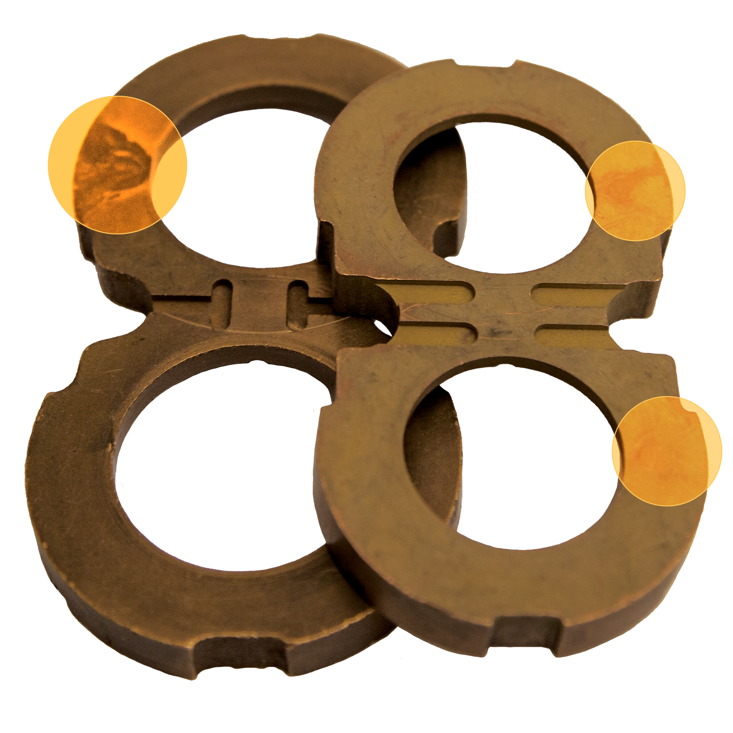
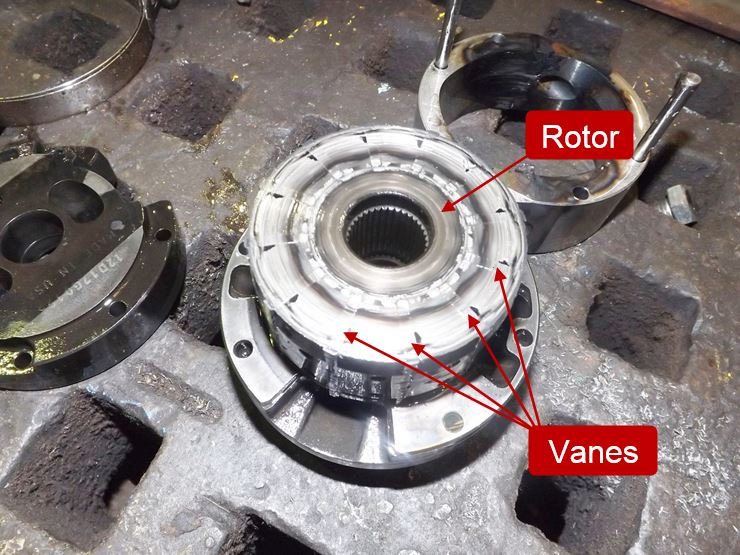
Simply put, cavitation is the formation of vapor cavities in the hydraulic oil. In hydraulic pumps, cavitation will occur any time the pump is attempting to deliver more oil than it receives into the suction (inlet) line. This is commonly referred to as “starvation” and results from a partial vacuum in the suction line. To fully illustrate what is happening when this occurs, we need to discuss vapor pressure. Vapor pressure is the pressure below which a liquid at a given temperature will become a gas, and this pressure varies significantly depending on the liquid. Generally, as the temperature of a liquid rises, the vapor pressure will proportionally increase. Likewise, as the temperature decreases, the vapor pressure will decrease. Most of us know that water will boil (turn to vapor) at 212°F (100°C) at 14.7 PSI (atmospheric pressure at sea level). In other words, the vapor pressure of water at 212°F is 14.7 PSI. If the pressure is reduced, the temperature at which the water boils will be reduced. If the temperature is lowered, the vapor pressure will decrease. In fact, water will boil at room temperature if the pressure is sufficiently reduced! The same principle applies to hydraulic oil, although the vapor pressure will be somewhat different than that of water. The vapor pressure of hydraulic oil is somewhere between 2 and 3 PSI at normal temperatures. In ideal conditions, the pressure in the suction line of the pump will be around 14.7 PSI at sea level. Of course, this pressure decreases with altitude, but sufficient pressure will normally be maintained in the suction line to prevent cavitation of the oil. However, if the pressure in the suction line of the pump is sufficiently reduced to the vapor pressure of the oil, vapor cavities will form. As the oil passes from the suction line to the outlet of the pump, the pressure will increase and the vapor cavities will implode violently. These extremely powerful implosions will cause erosion and premature failure of the pump components. In fact, a brand-new pump can be destroyed in a matter of minutes if the cavitation is severe enough. The picture below shows a rotor and cam ring from a vane pump that had failed due to severe cavitation.
In my 35-plus years of troubleshooting hydraulic components, this is the worst case of cavitation damage I have ever seen. In addition to the usual erosion of the parts, the vanes were actually fused to the rotor slots! Although this is an extreme example, it shows the potential damage to a pump due to cavitation. The good news is that cavitation is preventable and we will look at several conditions that can trigger this phenomenon.

Pump cavitation is one of the most searched topics on fluid power, which is justified, because cavitation is unfortunately an all-too-common cause of pump failure on mobile equipment. Liquids are able to hold dissolved gasses in solution, and the gas saturation level within any liquid is dependent upon the pressure, the temperature and the type of liquid itself, among other things. Cavitation is literally the bubbles spontaneously formed during conditions that prevent the liquid from holding that gas in saturation, such as a drop in relative pressure.
The best example to explain the gas saturation concept and the cavitation principle can be found for a couple bucks at the convenience store—a trusty bottle of soda pop. To ensure the pop is fizzy when it hits your lips, carbon dioxide is super-saturated within the delicious beverage, and pressure maintains that artificial level of fizz until you open the bottle. Upon opening the bottle, you can see cavitation at work, as bubbles seem to form out of nowhere, and other than the fact hydraulic fluid simply has common air dissolved within itself, the principle is the same.
The problem with my example is in trying to translate some harmless bubbles that tickle your taste buds into the damage that can eat away at solid metal. Cavitation bubbles themselves do little damage just floating around in your hydraulic oil, but it’s when the bubbles reach the pressure side of your pump that they do their harm.
Cavitation bubbles would rather form within the imperfections on the surface of the metal parts of your pump, such as the lens plate of a piston pump, or the gear of a gear pump, rather than just popping into existence in the middle of the fluid. The damage from cavitation occurs when the bubbles make their way around to the pressure size of the pump, where they implode under pressure, creating super-hot jets of fluid that pierce the bubble. Because the bubbles are most often located on metal parts, these little implosion jets heat up the surface of the metal, and you end up with little pits that destroy the pump’s efficiency until it just can’t pump at all.
Cavitation is difficult to detect on mobile equipment because of the noise of the engine or the machine itself, but if it ever sounds like someone threw a bag of marbles into your pump, it’s probably a result of cavitation. However, a diesel engine knock sounds not-unlike cavitation, making it difficult to distinguish cavitation noise, especially from inside the cab. Also, cavitation can be unnoticeable even in quiet ambient conditions if it’s not severe, and damage may not be discovered until the pump fails.
Because cavitation is bad, and cannot be corrected or repaired by your dentist, I’m going to give you seven tips on how to avoid cavitation in your hydraulic system. If these tips are heeded, I promise you cavitation will be a thing of your past, like your plaid grunge look or that weekend in Bangkok.
1 – Don’t use a suction strainer. Suction strainers are installed in the reservoir on the suction line of the hydraulic pump. They are intended to protect the pump from ingesting dirt and filth, which should subsequently protect the pump. However, think about the method in which a suction strainer prevents dirt from entering the pump; it collects it across its flow path. Larger particles and other junk get trapped in the suction strainer, but over time it gets clogged.
Most often, maintenance personnel don’t know the power unit even has a suction strainer, so it can get overlooked during routine maintenance, especially because most mobile reservoirs have no clean-out panel. Don’t get me wrong, it could take an easy decade to clog a suction filter, but when it does clog, it will cause slowly increasing levels of cavitation. You might as well have a clamp over the suction hose that you tighten at regular intervals. The biggest problem I have with suction strainers is that they’re redundant anyway if your hydraulic system is designed and maintained well to begin with.
2 – Ensure pumps have flooded suction. A pump can create vacuum at the inlet port to pull up fluid a short distance, but excessive pump head height will cause cavitation. A flooded suction condition uses the force of gravity and atmospheric pressure to push fluid into the pump, rather than the pump having to draw it in. A flooded suction is easy for PTO-mounted pumps because the pumps sit so low in the chassis, but with pumps driven off the engine, you may want to consider mounting your tank high on the machine to compensate for the long run to the front of the truck. With a pump mounted below or to the side of the reservoir, cavitation is nearly impossible unless something catastrophic occurs, like a rag being thrown into the reservoir and blocking the suction line.
3 – Don’t leave rags in the reservoir. It may sound ridiculous for me to offer that as a suggestion, but every hydraulic technician worth their weight in oil counts the number of rags they show up to and leave a job with. The best tools for cleaning out reservoirs are rags, and you will have to trust me when I say that it’s more common than you’d think to leave them in the reservoir. And if you leave a rag in the reservoir, it will most definitely find its way to the suction tube of the pump(s), starving them and causing cavitation.
While we’re at it, be considerate of more than just rags when maintaining a hydraulic machine. I’ve heard of tools, cell phones and dead animals finding their way into reservoirs, not all of which can clog a suction strainer or pump inlet, but their existence there is cause for concern. For a possum to make its way into a tank for a nap, a cover must have been left off, and this lack of consideration for the hydraulic system is unacceptable. Reservoirs are buttoned up for a reason, so I recommend keeping it that way if you care about the health of your machine.
4 – Properly size inlet plumbing. The recommended maximum velocity for suction lines is only a few feet per second, and because the relative action of fluid being “pulled” into the pump already causes a drop in suction pressure, the condition of sucking too much fluid through a small straw will cause cavitation. By simply sizing suction plumbing large enough, especially if you’re running a pump far from the reservoir, you can reduce the chance of cavitation.
5 – Use high quality hydraulic fluid. The quality of hydraulic fluid is often overlooked, and unfortunately, the good stuff is very expensive. Synthetic hydraulic fluid has many properties making it superior to standard dino oil, which has limited capacity to work well outside a narrow window of operating conditions. Speaking on viscosity alone, thicker oil is harder to pump and is more prone to cavitation.
Problems occur during machine start-up, such as on a cold morning, when standard hydraulic fluid is rather thick, making it difficult to pump. If cold and thick oil is not given time to warm before the machine is run at full pressure, cavitation could result. Even if the period of cavitation is short, because oil can heat quickly, the damage can accumulate during every cold start. By switching to synthetic fluid with a high viscosity index, you help ensure cold starts provide little drama. Viscosity index is the quality of oil to maintain its tested viscosity over a wide temperature range, and the bigger the number, the better. So even with a 46 cSt oil which could be prone to cavitating a pump at 20° below if it were normal oil, a high quality oil will still be relatively thin and easy to pump.
6 – Heat your hydraulic oil. Odd as it may sound, because heating oil in mobile machinery is rare, heating the oil before machine start-up can also help prevent cavitation due to cold-related high-viscosity. You wouldn’t fire up your rig and drive off without letting the engine warm up, so the same consideration should be paid to the hydraulic system. Oil doesn’t need much time to come up to temperature in most cases, so just running the pump to circulate oil through the system and operating some low pressure functions could heat up the oil before the serious work begins.
7 – Keep your oil dry. This recommendation comes from a specific example of pump cavitation, which could have been prevented by considering a few of these tips. This brutal past winter broke down more than one hydraulic machine, and this particular example occurred on a half-dozen machines powered by a 12 VDC electric power unit. Excessive water saturation within these power units caused ice to form on the suction strainers, both cavitating the pumps and imploding the strainers.
By following these tips, your chances of experiencing pump cavitation are slim to none. Mobile hydraulic systems already have so much to worry about; creating conditions conducive to cavitation should not be one of them.

Frequently occurring in pumping applications, cavitation creates bubbles or vapor cavities in a liquid as a result of rapid changes in pressure. These liquid-free voids typically form in low-pressure zones and can burst when subjected to high pressures, sending powerful shockwaves throughout the entire application.
Manufacturers in the chemical processing, food processing, and petroleum industries must consider the risk of cavitation when designing machinery in order to avoid unwanted noise, vibration, and component damage.
Cavitation decreases an application’s efficiency over time and puts repeated stress on critical pump parts, shortening their overall lifespan. Shockwaves can cause significant damage to the pump, which in turn leads to premature valve failure, decreased flow pressure, and, ultimately, breakage. If you’re experiencing any of these issues with your pumping application, our in-house pump experts can help.
There are two types of cavitation that may occur in reciprocating positive displacement applications: suction and discharge. Suction cavitation occurs ahead of the suction stroke, when the pump is starved of flow, either from being in a high-vacuum or low-pressure environment. The opening of the valve is delayed by inertia, causing a lower flow rate on the suction side and resulting in expansion, pressure decrease, and the formation of bubbles close to the plunger.
Discharge cavitation occurs when the pump’s discharge pressure is too high. Under these conditions, it’s difficult for the fluid to flow out of the pump. Instead, it continues moving at high velocities inside the working chamber, forming bubbles in the process.
When working with pumping applications in a processing industry, cavitation should always be kept in mind; being able to recognize the warning signs and identify the root causes of cavitation in your machinery can significantly reduce the risk of long-term damages, saving both time and money.
Triangle Pump has nearly a century of experience assisting clients with pump issues such as cavitation. Our pump components are designed to preserve expensive parts such as crankshafts and power frames by transferring the majority of wear to less expensive, more expendable parts such valves, plungers, and packing.

The phenomenon of cavitation consists in the disruption of continuity in the liquid where there is considerable local reduction of pressure. The formation of bubbles within liquids (cavitation) begins even in the presence of positive pressures that are equal to or close to the pressure of saturated vapor of the fluid at the given temperature.
Various liquids have different degrees of resistance to cavitation because they depend, to a considerable degree, upon the concentration of gas and foreign particles in the liquid.
The mechanism of cavitation can be described as follows: Any liquid will contain either gaseous or vaporous bubbles, which serve as the cavitation nuclei. When the pressure is reduced to a certain level, bubbles become the repository of vapor or of dissolved gases.
This process of condensation takes place fairly quickly, accompanied by local hydraulic shocks, the emission of sound, the destruction of material bonds and other undesirable phenomena. It is believed that reduction in volumetric stability in most liquids is associated with the contents of various admixtures, such as solid unwetted particles and gas-vapor bubbles, particularly those on a submicroscopic level, which serve as cavitation nuclei.
A critical aspect of the cavitation wear process is surface destruction and material displacement caused by high relative motions between a surface and the exposed fluid. As a result of such motions, the local pressure of the fluid is reduced, which allows the temperature of the fluid to reach the boiling point and small vapor cavities to form.
When the pressure returns to normal (which is higher than the vapor pressure of the fluid), implosions occur causing the cavity or vapor bubbles to collapse. This collapse of bubbles generates shock waves that produce high impact forces on adjacent metal surfaces and cause work hardening, fatigue and cavitation pits.
Thus, cavitation is the name given to a mechanism in which vapor bubbles (or cavities) in a fluid grow and collapse due to local pressure fluctuations. These fluctuations can produce a low pressure, in the form of vapor pressure of the fluid. This vaporous cavitation process occurs at approximately constant temperature conditions.
Vaporous cavitation is an ebullition process that takes place if the bubble grows explosively in an unbounded manner as liquid rapidly changes into vapor. This situation occurs when the pressure level goes below the vapor pressure of the liquid.
Gaseous cavitation is a diffusion process that occurs whenever the pressure falls below the saturation pressure of the noncondensable gas dissolved in the liquid. While vaporous cavitation is extremely rapid, occurring in microseconds, gaseous cavitation is much slower; the time it takes depends upon the degree of convection (fluid circulation) present.
Cavitation wear occurs only under vaporous cavitation conditions - where the shock waves and microjets can erode the surfaces. Gaseous cavitation does not cause surface material to erode.
It only creates noise, generates high (even molecular level cracking) temperatures and degrades the chemical composition of the fluid through oxidation. Cavitation wear is also known as cavitation erosion, vaporous cavitation, cavitation pitting, cavitation fatigue, liquid impact erosion and wire-drawing.
Cavitation wear is a fluid-to-surface type of wear that occurs when a portion of the fluid is first exposed to tensile stresses that cause the fluid to boil, then exposed to compressive stresses that cause the vapor bubbles to collapse (implode).
This collapse produces a mechanical shock and causes microjets to impinge against the surfaces, unifying the fluid. Any system that can repeat this tensile and compressive stress pattern is subject to cavitation wear and all the horrors accompanying such destructive activity.
Cavitation wear is similar to surface fatigue wear; materials that resist surface fatigue (hard but not brittle substances) also resist cavitation damage.
Liquid is the medium that causes cavitation wear. Cavitation wear does not require a second surface; it requires only that high relative motion exists between the surface and the fluid. Such motion reduces the local pressure in the fluid. When the liquid reaches its boiling point and ebullition occurs, vapor bubbles form, which produces cavitation.
Each vapor cavity lasts a short time because almost any increase in pressure causes the vapor in the bubble to condense instantaneously and the bubble to collapse and produce a shock wave. This shock wave then impinges on adjacent metal surfaces and destroys the material bonds.
Figure 1 depicts the collapse of a vapor bubble and the birth of a microjet. Cavitation is generally found where a hydrodynamic condition, characterized by a sudden and gross change in hydrostatic pressure, exists. Because ebullition can occur the instant pressure drops, vapor bubbles form and collapse frequently and quickly.
Entrained air and dust particles in the fluid serve as nucleation sites for the formation of vapor cavities. These nuclei can be small gas-filled pockets in the crevices of the container or simply gas pockets on contaminant particles moving freely in the flow stream. Therefore, all confined fluids may contain sufficient impurities to produce cavitation.
Small voids near the surface or flow field, where minimum pressure exists, indicate that cavitation has begun. Once initiated, bubbles continue to grow as long as they remain in low-pressure regions. As the bubbles travel into high-pressure regions, they collapse, producing intense pressures and eroding any solid surfaces in the vicinity.
Equipment users can detect cavitation audibly, visually, by acoustical instrumentation, by machine vibration sensors, through sonoluminescence measurement or by a decrease or change in performance from that produced under single-phase flow conditions (for example, loss of flow, rigidity and response).
Under cavitating flow conditions, the wear rate can be many times greater than that caused by erosion and corrosion alone. Cavitation wear can destroy the strongest of materials - tool steels, stellites, etc. Such damage can occur rapidly and extensively.
The amount of damage that cavitation causes depends on how much pressure and velocity the collapsed bubbles create. As a result of this pressure and velocity, the exposed surface undergoes a variety of widely varying intensities.
Each imposition lasts only a short time; the impulse magnitudes and collapse times are greater for larger bubbles at given collapsing pressure differentials. Thus, the greater the tensile stress on the fluid (the lower the static pressure), the larger the bubbles, the more intense the cavitation and the more serious the damage.
The impulses that result when vapor bubbles form and collapse cause individual symmetrical craters and permanent material deformations when the collapse occurs next to the surface. Consequently, cavitation damage, like fatigue failure, has several periods of activity:
So the region where damage occurs is often quite separate from the region in which cavities are created - often leading to an incorrect diagnosis of the problem. Cavitation wear is mechanical in nature and cannot occur without the application of the tensile and compressive stresses.
In leakage paths (across seals, valve seats and spool lands) where high velocities cause pressure levels to drop below the vapor pressure of the fluid (a cavitation condition often referred to as wire-drawing) and
Cavitation disturbs the normal operating conditions of fluid-type mechanical systems and destroys the surfaces of components. The process consists of cavities forming when pressures are low, the growth of subsequent bubbles as pressure stabilizes and finally the collapse of the bubbles when the cavities (gaseous or vaporous bubbles) are exposed to high-pressure.
Note that the pressure drop across the component is the driving force for cavitation wear. Figure 2 depicts the cavitation process that occurs in a gear pump and in a spool valve showing how cavities generate, grow and collapse in fluid-type components.
In cavitation wear, microcracks propagate to the point where the material can no longer withstand the impulse load that the imploding vapor bubbles impose. Therefore, particles finally break off and enter the system.
Therefore, a rough surface is prone to cavitation wear and because pittings and a rough profile characterize the cavitation damage, the damage increases as the surface becomes rougher.
The most basic means of combating cavitation wear is to minimize the tensile stress on the fluid. In other words, the equipment users must lower the level of refraction or vacuum conditions in zones of possible cavitation. In particular, the following steps may be appropriate:
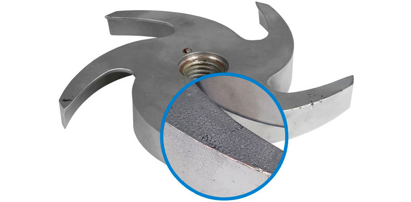
In many cases, design engineers can minimize cavitation damage by properly selecting fabrication materials. For example, stainless steel may be selected instead of aluminum (Figure 3) and use hard facing with a cavitation-resistant alloy on the exposed surface. Rubber and other elastomeric coatings have also helped minimize cavitation wear. Despite their low resistance to cavitation, these surfaces reflect the shock wave without causing intense damage.
The size of the particles generated by cavitation wear is a function of the Brinell hardness of the exposed material. The largest particles occur during the accumulation period. The slopes of the cumulative particle size distribution curves increase as the strain energy of the material increases. The average size of the particles produced by cavitation decreases as the cavitation intensity increases.
When investigating a cavitation problem in a fluid system, you must identify all possible sources of low pressure (vacuum), high temperature (heat), and locations where air might be ingressing. The following list should serve as a guideline for identifying low pressure areas in a fluid system:
Reservoirs - sites where mechanical (agitation) type air entrainment occurs, swirling fluid exists, fluid impingement on liquid or solid surfaces, pressurized reservoir conditions, cyclonic flow at pump suction port, critical altitude (angled reservoir) occurring during operation that exposes the pump suction port to the atmosphere, jostling of the fluid due to movement over rough terrain and/or low reservoir fluid level that expose the pump suction port to the atmosphere.
Pump - small diameter conduits and/or ports, restrictive flow passages, flow diversions, and/or long suction line conditions, poor pump filling characteristics (restrictive internal flow passages, high pumping speed, overly large flow displacement); altitude too high to provide sufficient reservoir pressure to supply the pump at rated flow conditions; inadequate suction head to lift fluid to pump inlet level (that is, elevation between fluid level and pump intake too great), insufficient suction head to accelerate reservoir fluid to the rated flow conditions of the pump (non-responsive to the pump displacement demands).

When designing a hydraulic system, it is important to understand the difference between cavitation and aeration—and understand the damage they can create.
As previously discussed in our April issue, it is critical to maintain proper fluid levels in the reservoir to ensure the Net Positive Suction Head Available (NPSHA) is greater than the Net Positive Suction Head Required (NPSHR) by the pump.
Anytime the NPSHA is equal to the NPSHR, the flow instabilities in the fluid moving to and through the pump will be affected to the point cavitation can (and will be) generated.
Aeration is a process where air is circulated with, mixed with or dissolved in the hydraulic fluid. It is created when air leaks into the system through the pump seals, pipe fittings and unions, which are all areas where air leakage is common.
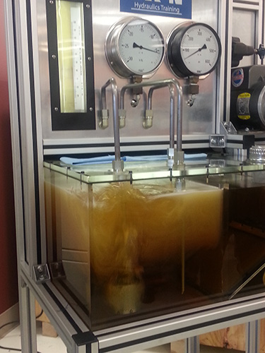
Although you can not see cavitation, a demonstration at Eaton’s training facility in Maumee, Ohio, shows an extreme example of the effects of excessive air in hydraulic fluid.
Cavitation, on the other hand, is the formation of gas bubbles that create vapor cavities in a liquid. It occurs when the gas bubbles in the liquid are subjected to rapid changes of pressure. This higher pressure causes the air bubbles to implode, which generates an intense miniature water hammer (shock wave). This shock wave creates significant wear as the gas bubbles implode on or near a metal surface, causing cyclic stresses through repeated implosions.
Cavitation occurs when the volume of fluid demanded by any part of a hydraulic circuit exceeds the volume of fluid being supplied. This causes the absolute pressure in that part of the circuit to fall below the vapor pressure of the hydraulic fluid. This will result in the formation of gas bubbles.
The difference between the two is in how the air is getting into the system. Cavitation is caused by NPSHA, and can be stopped by simply slowing the fluid flowing through the system. If the problem is aeration, on the other hand, you have to locate and isolate the air leaking into the system, so resolving the problem can be more time-consuming. The damage by both is equal, however.
Abnormal noise in hydraulic systems is often caused by aeration and/or cavitation. Air in the hydraulic fluid makes a banging or knocking noise when it experiences high and low system pressures as it circulates through the system.
In addition to damaging seals and reducing the service life of the hydraulic fluid, high fluid temperature can cause damage to system components through boundary lubrication as a result of excessive thinning of the oil film (lower viscosity index), which in turn causes full film lubrication loss.
Slow operation, or a reduction in system performance, is often the first indication that there is something wrong. In a hydraulic system, flow controls speed and response. Therefore, a loss of speed indicates a loss of flow.
Consequences of cavitation in a hydraulic system can be serious. Cavitation causes metal erosion, thus damaging the system components and contaminating the fluid. Cavitation can also cause mechanical failure of system components.
Cavitation can occur anywhere within the hydraulic circuit; however, hydrodynamic cavitation commonly occurs at the pump. The pump suction line between the reservoir and pump should be open and not restricted. If the pump has an inlet strainer or filter, it is important to prevent it from becoming clogged. A partially closed suction valve or restricted intake line will cause the velocity of the fluid in the intake line to increase, causing the boiling temperature of the fluid to decrease as the fluid pressure goes below vapor pressure. This will vaporize some of the fluid molecules.
The damage caused by unresolved cavitation to a hydraulic system can be extremely expensive and cause extensive downtime. Prevent this problem with proper system design and maintenance. And always, listen to your hydraulic system. A rattling or knocking noise is not the sound of a welcome visitor.

Across any pumping system there is a complex pressure profile. This arises from many properties of the system: the throughput rate, head pressure, friction losses both inside the pump and across the system as a whole. In a centrifugal pump, for example, there is a large drop in pressure at the impeller’s eye and an increase within its vanes (see Figure 1). In a positive displacement pump, the fluid’s pressure drops when it is drawn, essentially from rest, into the pumping chamber. The fluid’s pressure increases again when it is expelled.
If the pressure of the fluid at any point in a pump is lower than its vapour pressure, it will literally boil, forming vapour bubbles within the pump. The formation of bubbles leads to a loss in throughput and increased vibration and noise. However, when the bubbles pass on into a section of the pump at higher pressure, the vapour condenses and the bubbles implode, releasing, locally, damaging amounts of energy. This can cause severe erosion of pump components.
To avoid cavitation, it is important to match your pump to the fluid, system and application. This is a complex area and you are advised to discuss your application with the pump supplier.
The obvious symptoms of cavitation are noise and vibration. When bubbles of vapour implode they can make a series of bubbling, crackling, sounds as if gravel is rattling around the pump housing or pipework. In addition to the noise, there may be unusual vibrations not normally experienced when operating the pump and its associated equipment.
With centrifugal pumps, the discharge pressure will be reduced from that normally observed or predicted by the pump manufacturer. In positive displacement pumps, cavitation causes a reduction in flow rather than head or pressure because vapour bubbles displace fluid from the pumping chamber reducing its capacity.
Power consumption may also be affected under the erratic conditions associated with cavitation. It may fluctuate and will be higher to achieve the same throughput. Also, in extreme cases, when cavitation is damaging pump components, you may observe debris in the discharged liquid from pump components including seals and bearings.
Under the conditions favouring cavitation, vapour bubbles are seeded by surface defects on metal components within the pump: for example, the impeller of a centrifugal pump or the piston or gear of a positive displacement pump. When the bubbles are subjected to higher pressures at discharge they implode energetically, directing intense and highly focussed shockwaves, as high as 10,000MPa, at the metal surface on which the bubbles had nucleated. Since the bubbles preferentially form on tiny imperfections, more erosion occurs at these points.
When a pump is new, it is more resistant to cavitation because the metal components have few surface imperfections to seed bubble formation. There may be a period of operation before any damage occurs but, eventually, as surface defects accumulate, cavitation damage will become increasingly apparent.
Classic (or classical) cavitation occurs when a pump is essentially starved of fluid (it is also called vaporization cavitation and inadequate NPSH-A cavitation). This can occur because of clogged filters, narrow upstream pipework or restricting (perhaps partially closed) valves. If the pump is fed from a tank, the level of liquid (or pressure above it) may have fallen below a critical level.
In a centrifugal pump, ‘classic’ cavitation occurs at the eye of the impeller as it imparts velocity on the liquid (see Figure 1). In a positive displacement pump, it can happen in an expanding piston, plunger or suction-side chamber in a gear pump. Reciprocating pumps, for example, should not be used in self-priming applications without careful evaluation of the operating conditions. During the suction phase, the pump chamber could fill completely with vapour, which then condenses in a shockwave during the compression phase.
Vane Passing Syndrome, also known as vane syndrome, is a type of cavitation that occurs when the spacing between the vanes of a centrifugal pump’s impeller and its housing is too small, leading to turbulent and restricted flow and frictional heating. The pumped liquid expands as it passes beyond the constriction and cavitation occurs.
Suction recirculation (also called internal recirculation) is a potential problem observed with centrifugal pumps when operated at reduced flow rate. This might occur, for example, when a discharge valve has been left partially closed or when the pump is being operated at a flow below the minimum recommended by the pump manufacturer. Under these conditions, liquid may be ejected from the vanes back towards the suction pipe rather than up the discharge port. This causes turbulence and pressure pulses throughout the pump which may lead to intense cavitation.
Air can be sucked into a pumping system through leaking valves or other fittings and carried along, dissolved in the liquid. Air bubbles may form within the pump on the suction side, collapsing again with the higher pressure on the discharge side. This can create shock waves through the pump.
To avoid cavitation, the pressure of the fluid must be maintained above its vapour pressure at all points as it passes through the pump. Manufacturers of centrifugal pumps specify a property referred to as the Net Positive Suction Head Required or NPSH-R – this is the minimum recommended fluid inlet pressure. The documentation supplied with your pump may contain charts showing how NPSH-R varies with flow.
In fact, NPSH-R is defined as the suction-side pressure at which cavitation reduces the discharge pressure by 3%: a pump is already experiencing cavitation at this pressure. Consequently, it is important to build in a safety margin (about 0.5 to 1m) to take account of this and other factors such as:
Positive displacement pumps require an inlet pressure to be a certain differential greater than the vapour pressure of the fluid to avoid cavitation during the suction phase. This is discussed in terms of Net Positive Inlet Pressure (NPIP) in a similar manner to NPSH for centrifugal pumps. NPSH is measured in feet or meters and NPIP is measured in pressure such as psi or bar. When converted to the same units, NPSH and NPIP are the same. Manufacturers may quote NPIP-R as the recommended inlet pressure and provide charts showing how it varies with pump speed. The available or actual inlet pressure on an operating system is termed NPIP-A.
Cavitation is a potentially damaging effect that occurs when the pressure of a liquid drops below its saturated vapour pressure. Under these conditions it forms bubbles of vapour within the fluid. If the pressure is increased again, the bubbles implode, releasing damaging shockwaves. This can cause severe erosion of components. A common example of cavitation is when a centrifugal pump is starved of feed: vapour bubbles form in the eye of the impeller as it imparts velocity on the liquid and collapse again on the discharge side of the vanes as the fluid pressure increases. This can lead to damage to an impeller’s vanes, seal or bearing. Cavitation can also occur in positive displacement pumps such as gear pumps and plunger pumps.
With a centrifugal pump, ensure that NPSH-A is at least 0.5m greater than NPSH-R during operation. For example, if the pump is fed from a tank, ensure that the level of liquid in the tank (or pressure above it) is sufficient. For a positive displacement pump, make sure that the inlet pressure complies with the manufacturer’s NPIP requirements.

Most modern hydraulic pumps are reliable, robust pieces of equipment that will withstand years of constant service. However, any hydraulic pump can suffer from mechanical issues. Aeration and cavitation are two serious problems that can affect a hydraulic pump, and either problem can cause serious damage if the issue is ignored.
However, it can be difficult to figure out if a malfunctioning pump is suffering from aeration or cavitation, as the two problems tend to produce similar symptoms. Despite these similarities, aeration and cavitation have different causes and require different solutions, so knowing the difference between the two problems is vitally important knowledge for any hydraulic pump user.
All hydraulic pumps contain a small amount of air, which provides space for the pump"s hydraulic fluid to expand into as it heats up. However, excessive amounts of air in a hydraulic system can cause serious problems.
Aeration in hydraulic pumps occurs when air is drawn into the pump"s hydraulic fluid supply. Air can infiltrate your system through perished pump seals, damaged pipe connectors, leaking suction lines, and other forms of damage. This unwanted air mixes with and dissolves into the hydraulic fluid supply.
Hydraulic fluid that has been contaminated by exposure to air loses many of its functional properties. For example, hydraulic fluid containing excess air cannot conduct heat as efficiently, so aeration can cause rapid overheating in affected pumps and other hydraulic systems. Serious aeration can also impede the pump"s stroke cycle, causing a significant drop in usable power.
For a hydraulic pump to function properly, the flow of fluid from the pump"s reservoir to the pump itself must remain constant and unimpeded. If this flow speeds up or slows down for any reason (such as improper pressure settings or a block in the suction line), this can lead to a potentially catastrophic problem known as cavitation.
When a running hydraulic pump does not receive hydraulic fluid at the proper rate, fluid pressure in the pump"s suction line can drop dramatically. This causes the formation of bubbles inside the hydraulic fluid, which contain air and vaporized hydraulic fluid. These bubbles subsequently collapse, creating an incredible amount of force and heat.
The shockwaves created by these imploding bubbles can do an incredible amount of damage to a hydraulic pump in a short space of time. The pump"s impellers and interior surfaces tend to be particularly badly affected by cavitation, and a pump that has suffered from extensive cavitation may need a complete rebuild before it can be used again.
While cavitation and aeration have different causes, they can produce similar problems, making proper diagnosis difficult. High hydraulic fluid temperatures, lowered pumping rates, and visibly damaged valve seals can all be caused by either cavitation or aeration.
Generally, the easiest way to tell the difference is by listening to the malfunctioning pump, as both types of problem usually produce distinct noises. A cavitating pump tends to produce a steady, rhythmic pattern of knocking or whining noises. Unusual noises produced by aeration are more erratic and random and tend to sound more like rattling than knocking.
However, it is important to note that cavitation and aeration are not mutually exclusive problems, and a poorly maintained hydraulic pump may suffer from both problems simultaneously. Combined aeration and cavitation can lead to a particularly damaging form of cavitation, known as gaseous cavitation.
If your hydraulic pump is suffering from any signs of cavitation or aeration, calling in a professional hydraulic repair service is usually the fastest way to get to the bottom of the problem. These services have access to specialized testing tools and equipment that can quickly detect cavitation and aeration and will be able to provide rapid and effective solutions.
If your hydraulic pumping system is not functioning as it should, and you think cavitation or aeration may be the cause, contact the hydraulic experts at Quad Fluid Dynamics, Inc., for professional advice.
While it’s common for people to think of a pump’s inlet as sucking in oil, in reality, it is atmospheric pressure doing the work. In essence, the weight of the atmosphere pushes the oil out of the reservoir and into a region of lower pressure—the inlet. Once the oil is forced from the reservoir and through the inlet, it then moves the volume of liquid into a region of decreasing volume to create flow. For this process to begin, there must be minimum pressure at the inlet of a hydraulic pump, as shown in the diagram below.
As you can see, the inlet of a pump plays a large role in how well it operates. Unfortunately, those designing and maintaining pump systems can become so focused on downstream flow that they overlook proper inlet maintenance. This can result in degradation of inlet function and serious problems such as cavitation.
Cavitation occurs when the absolute pressure on the inlet side of the pump is too low and air is drawn out of the solution, creating bubbles in the oil. As these bubbles get pushed around to the high-pressure outlet side of the pump, they collapse. This creates localized shock waves that blow bits of material out of the pump. It can also result in excessive heat and reduced lubrication that leads to friction and wear over time.
Cavitation can cause pump failure and it can damage other components of your system, which is why it is critical to examine the condition of the pump"s inlet on a regular basis.
PSI versus PSIA. What’s the difference? PSI, or pounds per square inch, is a unit of measurement for pressure used in the United States. PSIA describes the absolute pressure in psi, including the pressure of the atmosphere. Absolute pressure is also referred to as total pressure.
The energy it takes to lift oil through the suction line (including pressure drop due to flow). We refer to this action as Phase 1 pressure, because it represents the amount of energy it takes to accelerate the fluid through the pumps internal pathways and keep the pump full.
In order for a pump to function, atmospheric pressure must be greater than Phase 1 pressure + NPSH. Every pump has its own specifications regarding acceptable minimum/maximum inlet pressure, but we can use the example below to illustrate how to calculate it.
To begin, assume that you are maintaining an 18 GPM hydraulic pump. The NPSH is equal to 12 PSIA with standard hydraulic oil and 1800 RPM per manufacturer’s specifications.
If we apply the same numbers to a variable-volume pump, the result will be less acceptable. Here’s why: Imagine the pump is not in demand and is therefore being held off stroke, meaning there is no flow. When the pump is suddenly needed, it will come on stroke, requiring the column of oil in the suction line to accelerate. This sudden change in demand requires the pump pressure to accelerate from static to a pressure that is strong enough to move the oil and prevent cavitation.
Assume the pump strokes on in 70 milliseconds (msec). The volume of liquid that has to accelerate is 1.5in^2 x 18.1” = 27.1 cubic inch (cu. in.). Note: Since the entire column of oil in the pipe has to accelerate, we used a measurement of 18.1” instead of 12.1”.
These calculations reveal that the system is fine, because the pump requires a minimum 12 PSIA at its inlet to operate effectively. However, if this system was installed at 2,300 feet above sea level (13.4 PSIA), the pump would cavitate whenever it came on stroke.
The above example assumes no losses due to other plumbing, however, it is not uncommon to see elbow fittings on pump ports, which could add to losses in the inlet line.
In addition to maintaining good inlet conditions, any small leak on the inlet will entrain air, which is also bad for the pump. Small leaks will cause a pump to lose prime whenever the system is shut off, which means it will start dry and run dry until prime is re-established. For this reason, it is never a good idea to install hydraulic pumps above the fluid level. Rather, hydraulic systems designs should ensure that the pump inlet is flooded, i.e. the oil level is above the pump inlet. A ball valve can be used to isolate the pump from the reservoir in case it needs service, and a limit switch can be used on the ball valve to prevent the system from running if the ball valve isn’t fully open.
When a reliable hydraulic system suddenly starts exhibiting problems, one of the first types of components most technicians assume may need to be replaced are hydraulic pumps, yet the pump should be the last component evaluated since it is often very time-consuming to replace.
There are all sorts of “warning” symptoms a hydraulic system will exhibit long before pump failure. Some of the most common types are changes in the sounds the system makes while it is in operation. If the system suddenly starts sounding different from how it has before, this could indicate various types of problems.
Two of the more common changes in sound are a banging noise, much like water banging in plumbing pipes, and or a very high pitched shrieking noise, similar to the sound sticky car brakes make. These sounds indicate aeration and cavitation in the system, which we will discuss in more detail shortly.
Another thing to check if you notice the system is not working correctly is to verify the pump is turning. Some systems are designed so that you have to manually engage or switch the pump on. You would be surprised by how many system problems are due to the pump not being turned on!
The last thing to check before getting into troubleshooting the pump is the hydraulic fluid level. If the fluid level is too low, it will allow air into the system and cause operational problems. If you discover air in the system, you will need to remove it first to avoid pump failure.
Aeration occurs when air is introduced into the hydraulic system. This can be due to defective seals, through low tank fluid level allowing air into the pump inlet line, damaged inlet hoses and connections. It is easy t


 8613371530291