
what causes hydraulic pump whine in stock

Pump cavitation is first and foremost caused by insufficient flow. This happens when the volume of fluid being supplied doesn’t meet the demands of the hydraulic circuit, and the pressure at the suction end of the pump isn’t sufficient. This leads to the absolute pressure falling below the vapor pressure of the liquid, which leads to air bubbles being formed. These tiny bubbles implode as they pass through the system, creating shockwaves and causing pump vibrations.
The process of these bubbles forming and collapsing is done with a great deal of force, and leads to eventual metal erosion inside the pump. The mechanical damage caused by cavitation can have irreversible impacts on system components and may possibly lead to complete failure. Cavitation happens only on the suction side of the pump, and may be caused by a series of different malfunctions, including:
Cavitation is typically characterised as a high-pitched whining or screeching sound, and in some extreme cases, can present itself as a loud rattling sound. Whilst these hydraulic pump whine noises are generally the most obvious telltale signs of cavitation, other symptoms to look out for also include:
By design, hydraulic pumps contain a miniscule amount of air which allows space for the hydraulic fluid to heat up and expand. However, too much air in the pump can cause serious issues – this is known as aeration.
Aeration in a hydraulic pump occurs when there is an air leak in the suction line. When outside air enters the pump through a damaged connector, loose pump seal, pipe fitting, or any other damage, it gets drawn into the pump’s hydraulic fluid supply. This unwanted air quickly gets dissolved into the hydraulic fluid and leads to contamination.
Contaminated hydraulic fluid can have serious implications for the system, as the excess air means that it cannot conduct heat as efficiently and can cause the fluid to foam. This can lead to overheating and in some cases, a substantial decrease in power. Aeration may happen on both sides of the pump, and has several causes including:
Similar to cavitation, aeration is usually indicated by a sudden change in noise, which can sometimes make it difficult to differentiate between the two causes However, aeration tends to produce a more erratic low-pitched ‘rumbling’ or ‘rattling sound, as opposed to the more consistent whining noise of cavitation.
Every hydraulic pump makes some noise. If all is well with a pump, then this noise stays more or less the same. However, if something goes wrong with the pump or its connected system parts, then you may start to hear sounds that you haven"t heard before.
The fluid that flows through your system needs to move at a smooth and even rate. The pump has to deliver the fluid at a specific flow for things to work.
If something prevents the fluid from achieving and maintaining its optimum flow, then your pump may start to make unusual noises. For example, you may hear a high-pitched whine coming from the pump. This can be a constant or intermittent sound.
If your pump whines constantly, then you may have a cavitation problem. Here, the pump can"t deliver its fluid at the right volume or rate. There isn"t enough fluid coming through the pump"s suction line.
In some cases, this is a sign that your pump"s motor is on the wrong setting. So, the pump itself is working at the wrong speed to create the right flow.
A hydraulic pump might get noisy if one of its parts or connections has a problem. A faulty or failing pressure control, bearing, valve, seal, or coupling can make a noise you haven"t heard before.
In some cases, you may hear vibrating clunks as your pump works if you have a problem with a connecting pipe. A loose seal or connector might allow the pipe to move. It then passes vibrations along to the pump itself.
While some noise problems are easy to fix, some are a sign that your pump is close to the end of its working life. Sometimes, this is due to natural wear, usage, and age. However, in some cases, minor problems cause more widespread damage if you don"t fix them quickly.
For example, if you"ve had cavitation problems for a while, then your system may not have been getting the lubrication it needs; it may have overheated regularly. Even if you fix the cavitation issue, you may be left with a damaged pump that needs a more significant repair, rebuild, or replacement.
So, while new sounds or an increase in operating noise don"t necessarily mean that you have a serious pump problem, you should investigate any unusual noise. Typically, this is a sign that something isn"t working right.
A minor problem in your system could go on to cause significant damage. For an expert diagnosis, contact Quad Fluid Dynamics, Inc. Ourhydraulic pump repair and rebuild servicewill get your pump running smoothly and efficiently again.
Excessive or erratic hydraulic pump noise is a symptom of malfunction that could cause damage or accelerated wear if not addressed quickly and correctly. While it’s never nice to hear strange noises emitted from your pump, different forms of noise, which are related to different faults can provide valuable clues that can help you to diagnose your problem and get it fixed before it turns into something major.
So it pays to know what different pump noises mean and with practice you can quickly distinguish between the normal operating sounds and signs that something is wrong. In this article, we’ll talk about what causes some of these sounds, so you can identify them.
A constant hissing sound is indicative of a relief valve that is set too low or is stuck open and is continually releasing pressure. An erratic whistling sound is a symptom that a relief valve is set incorrectly or is damaged. It is common for pump settings to be changed carelessly or inadvertently - sometimes to overcome other issues with the hydraulic system - sometimes due to a lack of understanding of the correct operating conditions, so include this in your regular checks. In addition to noise problems, relief valve damage can be accompanied by slamming of actuators, stalls and excessive heat generation.
Noise issues are just one symptom that gives you a clue when things go wrong with your hydraulic pump. There are several other issues to know and understand, which could help you to identify pump problems quicker. Which means you can sort them out sooner - potentially saving big money down the road. These include heat problems, pressure problems and flow problems.

Longer cycle times are often the first indication that there is something wrong with a hydraulic system. Decreased speed of hydraulic actuators (such as cylinders) points to decreased flow through the system.
Decreased flow can be caused by either external or internal leaks. External leakage can often be spotted very easily. Look for leaking/busted hydraulic hose, hydraulic fluid around connectors or under components.
See the related blogs on preventive maintenance of hydraulic hoses and knowing when to replace a hydraulic hose. Another related blog, “What is Causing Your Hydraulic System to Leak” has a free download of our Port End Assembly Guide, which can educate your maintenance personnel on preventing connector leaks in the first place.
Internal leaks (such as high-pressure fluid passing around the cylinder piston, or incorrectly set relief valve pressure) are more challenging to identify. One way to identify an internal leak is by detecting elevated temperature of a failing component. A leak generates heat. Higher temperature results in decreased viscosity of the hydraulic fluid. Decreased viscosity of the fluid further increases leakage, leading to additional increases in temperature… You get the picture of how the situation escalates.
In some cases, temperature measurement is not conclusive. If an internal leak cannot be detected by locating a component generating abnormal heat, use a hydraulic flow meter.
Knocking, loud whining, or screeching often indicates aeration or cavitation. Aeration means air inclusion in the hydraulic fluid, cavitation is the presence of vaporized hydraulic fluid in the system.
Banging or knocking noises can indicate that air is included in the hydraulic fluid. Other symptoms of air inclusion are foaming of the fluid, and erratic actuator movements.
Air in the system accelerates breakdown of the hydraulic fluid and decreases hydraulic fluid’s lubricating properties. Both conditions lead to increased wear of the system’s components, through increased friction, overheating, and burning of seals.
Air usually enters the system through the pump intake. Check the fluid level and a condition of the suction hose. If the hose is old or shows any warning signs, replace it. See related blogs on knowing when to replace a hydraulic hose, scheduled hydraulic hose replacement, and preventive maintenance of hydraulic hoses for more information on the subject.
Cavitation results from demand for hydraulic fluid not being met. Typically (but not exclusively), this happens at the pump. The insufficient flow causes the absolute pressure in the affected part of the circuit to fall below the vapor pressure of the hydraulic fluid, which in turns causes formation of vapor cavities within the fluid. When the vapor cavities are compressed, they implode and produce a knocking noise.
Excessive temperature of hydraulic fluid (generally above 180°F), reduces its working life and damages seals in the system. In addition, viscosity of hydraulic fluid decreases with increasing temperature, which in turn results in inadequate lubrication and increased wear of the system"s components.
There are two general causes for increased hydraulic fluid temperature: either a component produces more heat than it should, or the heat dissipation capacity of the system is reduced/inadequate.
Regularly check the hydraulic oil level and viscosity. Check the heat exchanger for any obstructions in both coolant lines and hydraulic fluid lines. Make sure that the heat exchanger has adequate space around it.
To properly analyze and/or troubleshoot your hydraulic system, you will need some tools. At minimum, you need to be able to measure pressure, temperature, and flow at different parts of your circuit. The more complex your hydraulic system, the more sophisticated meters you will need to get the job done.
Parker SensoControl family of diagnostic meters offers four different diagnostic solutions to address the needs of maintenance personnel, based on the complexity of their hydraulic circuits.

The second leading cause of hydraulic pump failure, behind contamination, is cavitation. Cavitation is a condition that can also potentially damage or compromise your hydraulic system. For this reason, understanding cavitation, its symptoms, and methods of prevention are critical to the efficiency and overall health of not just your hydraulic pump, but your hydraulic system as a whole.
The product of excessive vacuum conditions created at the hydraulic pump’s inlet (supply side), cavitation is the formation, and collapse of vapors within a hydraulic pump. High vacuum creates vapor bubbles within the oil, which are carried to the discharge (pressure) side. These bubbles then collapse, thus cavitation.
This type of hydraulic pump failure is caused by poor plumbing, flow restrictions, or high oil viscosity; however, the leading cause of cavitation is poor plumbing. Poor plumbing is the result of incorrectly sized hose or fittings and or an indirect (not straight or vertical) path from the pump to the reservoir. Flow restrictions, for example, include buildup in the strainer or the use of an incorrect length of hose or a valve that is not fully open. Lastly, high oil viscosity—or oil that is too viscous—will not flow easily to the pump. Oil viscosity must be appropriate for the climate and application in which the hydraulic pump is being used.
The greatest damage caused by cavitation results from the excessive heat generated as the vapor bubbles collapse under the pressure at the pump outlet or discharge side. On the discharge side, these vapor bubbles collapse as the pressure causes the gases to return to a liquid state. The collapses of these bubbles result in violent implosions, drawing surrounding material, or debris, into the collapse. The temperature at the point of implosion can exceed 5,000° F. Keep in mind that in order for these implosions to happen, there must be high vacuum at the inlet and high pressure at the outlet.
Cavitation is usually recognized by sound. The pump will either produce a “whining” sound (more mild conditions) or a “rattling” sound (from intense implosions) that can sound like marbles in a can. If you’re hearing either of these sounds, you first need to determine the source. Just because you hear one of these two sounds doesn’t guarantee that your hydraulic pump is the culprit.
To isolate the pump from the power take-off (PTO) to confirm the source, remove the bolts that connect the two components and detach the pump from the PTO. Next, run the PTO with no pump and see if the sound is still present. If not, it is safe to assume your hydraulic pump is the problem.
Another sign you may be experiencing cavitation is physical evidence. As part of your general maintenance, you should be inspecting and replacing the hydraulic oil filter"s elements at regular intervals based on the duty cycle of the application and how often it is used. If at any time during the inspection and replacement of these elements you find metallic debris, it could be a sign that you’re experiencing cavitation in the pump.
The easiest way to determine the health of your complete hydraulic circuit is to check the filter. Every system should have a hydraulic oil filter somewhere in-line. Return line filters should be plumbed in the, you guessed it, return line from the actuator back to tank—as close to the tank as possible. As mentioned earlier, this filter will have elements that should be replaced at regular intervals. If you find metallic debris, your pump could be experiencing cavitation. You’ll then need to flush the entire system and remove the pump for inspection.
Conversely, if you’ve already determined the pump to be damaged, you should remove the filter element, cut it open, and inspect it. If you find a lot of metal, you’ll need to flush the entire system and keep an eye on the other components that may be compromised as a result.
Once cavitation has been detected within the hydraulic pump, you’ll need to determine the exact cause of cavitation. If you don’t, cavitation can result in pump failure and compromise additional components—potentially costing you your system.
Since the pump is fed via gravity and atmospheric pressure, the path between the reservoir and the pump should be as vertical and straight as possible. This means that the pump should be located as close to the reservoir as is practical with no 90-degree fittings or unnecessary bends in the supply hose. Whenever possible, be sure to locate the reservoir above the pump and have the largest supply ports in the reservoir as well. And don"t forget, ensure the reservoir has a proper breather cap or is pressurized (3–5 PSI), either with an air system or pressure breather cap.
Be sure the supply line shut-off valve (if equipped) is fully open with no restrictions. This should be a “full-flow” ball valve with the same inside diameter (i.d.) as the supply hose. If feasible, locate a vacuum gauge that can be T’d into the supply line and plumb it at the pump inlet port. Activate the PTO and operate a hydraulic function while monitoring the gauge. If it reads >5 in. Hg, shut it off, and resume your inspection.
A hose with an inner bladder vulcanized to a heavy spiral is designed to withstand vacuum conditions as opposed to outward pressure. The layline will also denote the size of the hose (i.d.). You can use Muncie Power’s PPC-1 hydraulic hose calculator to determine the optimal diameter for your particular application based on operating flows.
Another consideration, in regards to the inlet plumbing, is laminar flow. To reduce noise and turbulence at the pump inlet, the length of the supply hose should be at least 10 times its diameter. This means that any type of shut-off valve or strainer at the reservoir should be at least 10 diameters from the pump inlet. A flared, flange-style fitting at the pump inlet can also reduce pump noise by at least 50 percent compared to a SAE, JIC, or NPT fitting.
Selecting the proper viscosity of hydraulic fluid for your climate and application is also critical. Oil that is too viscous will not flow as easily to the pump. Consult your local hydraulic oil supplier for help selecting the optimal fluid viscosity.
By maintaining a regular maintenance schedule, remaining vigilant for any signs or symptoms, and taking preventative measures, the good news is that you should be able to prevent cavitation and experience efficient operation for the duration of your pump’s lifespan.
Poor plumbing is the leading cause of cavitation and can be prevented by selecting a properly sized hose, choosing the appropriate fittings, ensuring the most direct, straight routing from the pump to the reservoir, etc.
Hey everyone. We"ve recently started hearing a noise that sounds like it"s coming from our hydraulic pump. It usually only makes this sound at certain rpms and when the volume control is adjusted higher it seems to increase the noise. We have a 2014 Concord 40meter with less than 600 hrs
what kind of noise do you hear? when it appears, is it a constant noise, and when you adjust the volume, does it go away? i suspect, that there is a bearing inside the pump, that is not 100% anymore, possibly unbalanced, and at certain rpms/settings the noise intensifies, to the point that you can hear it.
Thank you for your reply. The noise is basically a higher pitched whining noise. It only makes the sound when rpms are turned up. If we are pumping at lower rpms and we turn volume up, it will also make the noise. You are actually the second person to suggest a bearing going out.
Try engaging the PTO in a gear Lower than normal. If it pumps in 7th gear, put the PTO in 6th gear. If the noise is the same, Exactly the same, it"s likely not a bearing issue. If the noise is still present but at a noticeably Lower pitch, then it"s possibly a bearing.
Check that the pump shaft is rotating. Even though coupling guards and C-face mounts can make this difficult to confirm, it is important to establish if your pump shaft is rotating. If it isn’t, this could be an indication of a more severe issue, and this should be investigated immediately.
Check the oil level. This one tends to be the more obvious check, as it is often one of the only factors inspected before the pump is changed. The oil level should be three inches above the pump suction. Otherwise, a vortex can form in the reservoir, allowing air into the pump.
What does the pump sound like when it is operating normally? Vane pumps generally are quieter than piston and gear pumps. If the pump has a high-pitched whining sound, it most likely is cavitating. If it has a knocking sound, like marbles rattling around, then aeration is the likely cause.
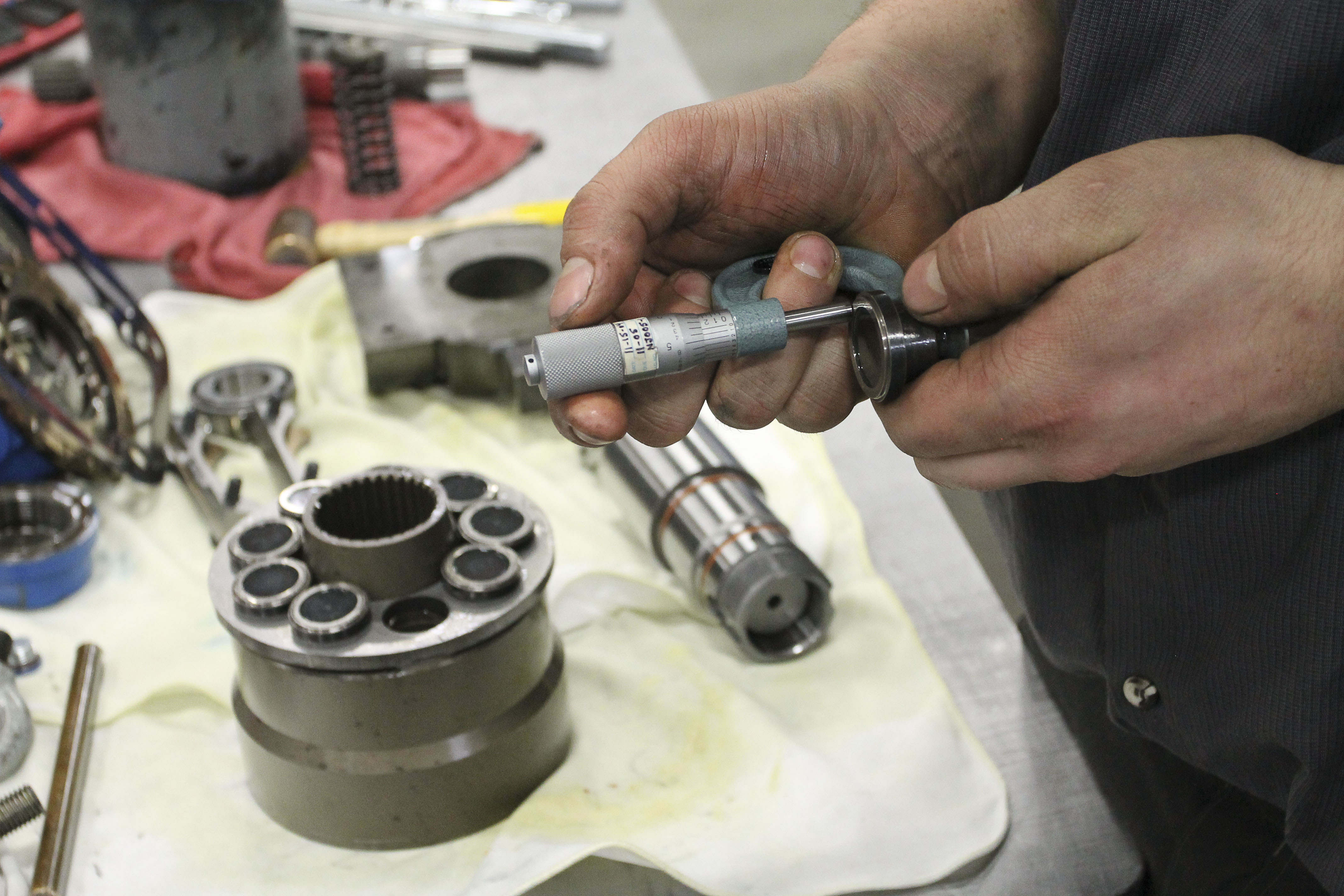
Cavitation is the formation and collapse of air cavities in the liquid. When the pump cannot get the total volume of oil it needs, cavitation occurs. Hydraulic oil contains approximately nine percent dissolved air. When the pump does not receive adequate oil volume at its suction port, high vacuum pressure occurs.
This dissolved air is pulled out of the oil on the suction side and then collapses or implodes on the pressure side. The implosions produce a very steady, high-pitched sound. As the air bubbles collapse, the inside of the pump is damaged.
While cavitation is a devastating development, with proper preventative maintenance practices and a quality monitoring system, early detection and deterrence remain attainable goals. UE System’s UltraTrak 850S CD pump cavitation sensor is a Smart Analog Sensor designed and optimized to detect cavitation on pumps earlier by measuring the ultrasound produced as cavitation starts to develop early-onset bubbles in the pump. By continuously monitoring the impact caused by cavitation, the system provides a simple, single value to trend and alert when cavitation is occurring.
The oil viscosity is too high. Low oil temperature increases the oil viscosity, making it harder for the oil to reach the pump. Most hydraulic systems should not be started with the oil any colder than 40°F and should not be put under load until the oil is at least 70°F.
Many reservoirs do not have heaters, particularly in the South. Even when heaters are available, they are often disconnected. While the damage may not be immediate, if a pump is continually started up when the oil is too cold, the pump will fail prematurely.
The suction filter or strainer is contaminated. A strainer is typically 74 or 149 microns in size and is used to keep “large” particles out of the pump. The strainer may be located inside or outside the reservoir. Strainers located inside the reservoir are out of sight and out of mind. Many times, maintenance personnel are not even aware that there is a strainer in the reservoir.
The suction strainer should be removed from the line or reservoir and cleaned a minimum of once a year. Years ago, a plant sought out help to troubleshoot a system that had already had five pumps changed within a single week. Upon closer inspection, it was discovered that the breather cap was missing, allowing dirty air to flow directly into the reservoir.
A check of the hydraulic schematic showed a strainer in the suction line inside the tank. When the strainer was removed, a shop rag was found wrapped around the screen mesh. Apparently, someone had used the rag to plug the breather cap opening, and it had then fallen into the tank. Contamination can come from a variety of different sources, so it pays to be vigilant and responsible with our practices and reliability measures.
The electric motor is driving the hydraulic pump at a speed that is higher than the pump’s rating. All pumps have a recommended maximum drive speed. If the speed is too high, a higher volume of oil will be needed at the suction port.
Due to the size of the suction port, adequate oil cannot fill the suction cavity in the pump, resulting in cavitation. Although this rarely happens, some pumps are rated at a maximum drive speed of 1,200 revolutions per minute (RPM), while others have a maximum speed of 3,600 RPM. The drive speed should be checked any time a pump is replaced with a different brand or model.
Every one of these devastating causes of cavitation threatens to cause major, irreversible damage to your equipment. Therefore, it’s not only critical to have proper, proactive practices in place, but also a monitoring system that can continuously protect your valuable assets, such as UE System’s UltraTrak 850S CD pump cavitation senor. These sensors regularly monitor the health of your pumps and alert you immediately if cavitation symptoms are present, allowing you to take corrective action before it’s too late.
Aeration is sometimes known as pseudo cavitation because air is entering the pump suction cavity. However, the causes of aeration are entirely different than that of cavitation. While cavitation pulls air out of the oil, aeration is the result of outside air entering the pump’s suction line.
Several factors can cause aeration, including an air leak in the suction line. This could be in the form of a loose connection, a cracked line, or an improper fitting seal. One method of finding the leak is to squirt oil around the suction line fittings. The fluid will be momentarily drawn into the suction line, and the knocking sound inside the pump will stop for a short period of time once the airflow path is found.
A bad shaft seal can also cause aeration if the system is supplied by one or more fixed displacement pumps. Oil that bypasses inside a fixed displacement pump is ported back to the suction port. If the shaft seal is worn or damaged, air can flow through the seal and into the pump’s suction cavity.
As mentioned previously, if the oil level is too low, oil can enter the suction line and flow into the pump. Therefore, always check the oil level with all cylinders in the retracted position.
If a new pump is installed and pressure will not build, the shaft may be rotating in the wrong direction. Some gear pumps can be rotated in either direction, but most have an arrow on the housing indicating the direction of rotation, as depicted in Figure 2.
Pump rotation should always be viewed from the shaft end. If the pump is rotated in the wrong direction, adequate fluid will not fill the suction port due to the pump’s internal design.
A fixed displacement pump delivers a constant volume of oil for a given shaft speed. A relief valve must be included downstream of the pump to limit the maximum pressure in the system.
After the visual and sound checks are made, the next step is to determine whether you have a volume or pressure problem. If the pressure will not build to the desired level, isolate the pump and relief valve from the system. This can be done by closing a valve, plugging the line downstream, or blocking the relief valve. If the pressure builds when this is done, there is a component downstream of the isolation point that is bypassing. If the pressure does not build up, the pump or relief valve is bad.
If the system is operating at a slower speed, a volume problem exists. Pumps wear over time, which results in less oil being delivered. While a flow meter can be installed in the pump’s outlet line, this is not always practical, as the proper fittings and adapters may not be available. To determine if the pump is badly worn and bypassing, first check the current to the electric motor. If possible, this test should be made when the pump is new to establish a reference. Electric motor horsepower is relative to the hydraulic horsepower required by the system.
For example, if a 50-GPM pump is used and the maximum pressure is 1,500 psi, a 50-hp motor will be required. If the pump is delivering less oil than when it was new, the current to drive the pump will drop. A 230-volt, 50-hp motor has an average full load rating of 130 amps. If the amperage is considerably lower, the pump is most likely bypassing and should be changed.
Figure 4.To isolate a fixed displacement pump and relief valve from the system, close a valve or plug the line downstream (left). If pressure builds, a component downstream of the isolation point is bypassing (right).
The most common type of variable displacement pump is the pressure-compensating design. The compensator setting limits the maximum pressure at the pump’s outlet port. The pump should be isolated as described for the fixed displacement pump.
If pressure does not build up, the relief valve or pump compensator may be bad. Prior to checking either component, perform the necessary lockout procedures and verify that the pressure at the outlet port is zero psi. The relief valve and compensator can then be taken apart and checked for contamination, wear, and broken springs.
Install a flow meter in the case drain line and check the flow rate. Most variable displacement pumps bypass one to three percent of the maximum pump volume through the case drain line. If the flow rate reaches 10 percent, the pump should be changed. Permanently installing a flow meter in the case drain line is an excellent reliability and troubleshooting tool.
Ensure the compensator is 200 psi above the maximum load pressure. If set too low, the compensator spool will shift and start reducing the pump volume when the system is calling for maximum volume.
Performing these recommended tests should help you make good decisions about the condition of your pumps or the cause of pump failures. If you change a pump, have a reason for changing it. Don’t just do it because you have a spare one in stock.
Conduct a reliability assessment on each of your hydraulic systems so when an issue occurs, you will have current pressure and temperature readings to consult.
Al Smiley is the president of GPM Hydraulic Consulting Inc., located in Monroe, Georgia. Since 1994, GPM has provided hydraulic training, consulting and reliability assessments to companies in t...

There’snothing quite like the high-pitched racket emitting from a hydraulic power unit. The combination of noises originates primarily at the hydraulic pump, but secondary harmonics and reverberations contribute to a cacophony, unlike any other machine noise. The telltale hydraulic whine is the bane of machine operators forced to mentally block the press/shear/extruder noise, raising their neck hair.
The hydraulic power unit noise problem isn’t lost on engineers and designers. As a result, manufacturers have designed components to be inherently smoother and quieter. Hydraulic designers may also select components less likely to contribute to the raucous sound. At the same time, technicians have options to ensure that as little of the vibrations as possible translate into annoying and potentially hazardous noise.
Pressure from the pump means turbulenceMuch of the attention applied to noise and vibration reduction is rightfully aimed squarely at the hydraulic pump. Most hydraulic pumps transform incoming mechanical energy into hydraulic energy discretely. Rather than feed a continuous stream of hydraulic fluid into the circuit, a pump sends individual packets of pressurized fluid to the outlet. Each discrete bundle of compressed hydraulic fluid blasts forth into the pressure line with a tiny wave of pressure.
No pump perfectly transmits pressure without bumps, corners, or turbulence, and each impedance encourages vibration and noise. More often than not, lens plates, gears, vanes, ports, and pistons all contain sharp edges, abrupt turns, or choked flow paths. The movement of fluid through a pump is far from laminar. Even if every metal pump component were chamfered, bevelled and honed, the resulting reduction in noise generation would likely be offset by the same reduction in efficiency.
From a design and installation perspective, the manufacturer holds responsibility for effort and ingenuity that must result in quieting solutions. In addition, a manufacturer must balance the varied demand asked of their pumps, which requires efficient operation across various pressure and flow outputs. A pump may be designed to limit pressure pulsations at 1,800 rpm and 3,000 psi but could do so poorly when run at 3,450 rpm and 1,000 psi, for example.
The pump pulsation is the primary NVH (Noise, Vibration & Harshness) driver. Each of those hydraulic energy bundles discharged from a pumping element (like a piston) or chamber (like vanes and gears) emits a pulse, and the frequency of those pulses dictates the timbre of the hydraulic noise. The frequency is a product of the prime mover rpm and the number of elements or chambers. A 9-piston pump running at 1,750 rpm results in 1,5750 pressure signals per minute. In acoustic terms, the pump’s fundamental frequency is 262.5 Hz (15,750 divided by 60 seconds in a minute) while also emitting high amplitude harmonics at 525 and 787.5 Hz.
By the same token, a pump may produce harmonics anywhere within the audible spectrum between 20 Hz and 20,000 Hz (or 11,500 Hz as tested for this author’s “old man ears” *see sidebar). Of course, we all know these harmonics combine to make annoying sounds, especially the harmonics falling between 1,000 & 5,000 Hz, where people’s hearing is most sensitive.
Looking at other sources of noise and vibrationMoreover, it’s essential to understand the rest of the hydraulic power unit’s contribution to amplifying noise. The prime mover and pump contribute most of the fundamental frequencies, but anything and everything attached to the power unit transmits and emits vibration and sound. An acoustic engineer could spend many times the cost of the power unit calculating and estimating how loud the power unit might be and at what frequencies. But sometimes, the particular sound and harmonics are unpredictable.
Let’s take the reservoir, for example. Its combination of welded plates, cut-outs, holes, and accessories sometimes augment the fundamental and harmonic frequencies emitted by the pump. Every physical body has a natural harmonic frequency, and sometimes those harmonics can overlap. When sound frequencies overlap with peaks atop peaks (Figure 1), the sound pressure level increases. Depending on the mass, size, shape, and elasticity of the object adding the resonance, the increase could range from barely audible to ear-splitting. When the dice fall against your favor, the reservoir may literally ring with resonance.
As much as possible should be done to isolate the pump from any possible harmonic contributor. The most obvious point of shared vibration is where the pump/motor attaches to the reservoir. Two traditional methods are common — vertical (in-tank) and horizontal (tank top). The L-Shape and elevated tank make great choices, but the prior two choices far outnumber the latter.
With vertical motor power units, the pump resides below the oil level through a large hole in the top surface where the bell housing attaches using (typically) four bolts in its flange. Any vibration in the pump or motor transmits directly to that top plate and any other metal welded, clamped, or bolted to the tank. The horizontally mounted pump uses a C-Face motor that directly couples the pump using a similar bell housing. However, these units employ foot mounting via the motor, but the opportunity still exists for the pump’s vibrations to transmit through the bell housing and motor to the tank top surface as well.
If you’ve designed or fabricated a hydraulic power unit, you know we don’t just weld or bolt the pump/motor group together and hope for the best. The damping of sound and vibration starts at the connection between the pump and motor. The drive couplers transfer the power from the motor to the pump and use a rubber insert tightly sandwiched between the couplers to reduce the vibration transfer from one to the other. The couplers and insert also help with shaft misalignment.
Any time you introduce elasticity to an interface, you reduce the natural frequency of the assembly. Elastomers (or actual springs) should be chosen with a natural frequency at least half that of the pump’s rotational frequency. For example, your 1,800 rpm motor’s 30 Hz frequency would best due with isolators offering 10 Hz or less. This theory applies not only to the coupler insert but the anti-vibration mounting feet (Figure 2) used to attach a horizontal pump/motor to the reservoir.
The individual mounting feet seen in Figure 2 are less prevalent in applications where the motor fully supports the pump via the bell housing. However, when foot-mounted pumps sit directly on the reservoir top and the motor is asked only to support its own weight, these act as a vibration buffer. For bell housing-mounted pumps, the solution is two-fold. First, rubber gaskets mounted between the motor C-Face and the bell housing provide a barrier for vibration and sound (and also work well in vertical pump power units). The motor is best mounted using vibration-damping bars as an additional isolation layer. Consisting of a thick rubber pad sandwiched between two steel bars, the damping bars allow the technician to bolt the pump to the top bar while welding the bottom directly to the tank.
Taking plumbing into considerationOf course, other components transmit sound and vibration besides the pump/motor group. You’d be surprised at how much sound energy transmits through plumbing, such as tubes and hoses. The steel of the tube or hose reinforcement vibrates readily in tune with specific harmonics, although the effect is mitigated by long lengths of plumbing, which have a lower natural frequency.
Figure 3. Having all hydraulic hose or steel tube in a high-pressure hydraulic system is a recipe for noise. Using a combination of steel tube with hose reduces cyclical radial expansion over a long hose but also isolates the tube from direct machine vibrations.
Sound emits not only from vibrating components but also through the hydraulic fluid itself. In fact, liquids transmit sound energy more efficiently than does air, so anywhere a conduit filled with oil goes, so too does pump noise. The creative use of pressure line accessories helps to dampen and absorb noise as it leaves the pump. Hydropneumatic accumulators charged to around 1/3 operating pressure and teed into the pressure line provide a damper to absorb pressure waves, thereby reducing noise energy.
Noise may come from unexpected sources, as well. One application took our team days to discover and remedy the solution. It was a standard hydraulic power unit with a vertical pump motor mount attached to an 80-gal reservoir. Mounted atop was a kidney loop circuit for filtration and cooling, which included a liquid-to-air cooler. We narrowed the noise down to the cooler, which was constructed using bent sheet metal to shroud the heat exchanger. Our choice of pump, along with steel tubing, created a harmonic resonance of the sheet metal.
Our fix was ad hoc, and through elimination, we changed to a different pump displacement, replaced the tube with hose, and then added two 90° elbows in series at the cooler inlet port. What previously gave the office workers headaches from the piercing noise morphed into your standard hydraulic whine. Even when all noise-reduction measures are heeded, sometimes the stars align to make a cacophony unintentionally with no way to predict the result.

The high-pitched mechanical tones of a tortured hydraulic system are often traced back to squealing hydraulic cylinders. A regimented troubleshooting procedure then makes haste to eliminate the noisome wail and determine whether more is going on here. Ask the right questions before jumping in, though, and avoid an unproductive repair experience. Does the squealing happen at all flow rates? Is stroke speed contributing to the problem? It’s this process of elimination that will get the gear mobile again, so let’s get our own system-diagnosing brains moving.
Aeration is a common factor in this situation. Aeration is simply a leak, one that usually occurs on the suction side of the mechanism. The resulting leak causes an erratic whine or squealing noise to propagate along the frame of the mobile gear, but it usually tracks back to the cylinder. Of course, as with any diligent system analysis process, the initial cause doesn’t always bring the story to a fast end. There’s the cause of the aeration to discover. Again, it’s a Sherlockian process of elimination that works best. Replace parts if necessary, but begin with cheaper replacements. The rod and piston seals make a fine start point, but this issue may not even be a mechanical problem, so what ails the cylinder?
If the cylinder is tested and found to be in optimal working condition, then what about checking the oil? Hydraulic fluid is vulnerable to atmospheric contamination, so a potential leak may originate at another point on the system but be carried into the cylinder. The oil foams or takes on the consistency of a soapy scum. The cylinder compresses, as it should, but the typically non-compressible oil squeezes the tiny air bubbles until they heat and release energy as that alarming shriek. Corrective actions at this point suggest an initial look at the oil, followed by an inspection of the couplings that hook the cylinder to the mobile vehicle. Now, if these tests don’t yield fruit, then and only then is it time to cause a stoppage by taking the cylinder back to the bench for further testing.
There’s a law that engineers find very useful when a troubleshooting protocol is active. It’s called Occam’s Razor. Basically, it states that the simplest answer is usually the correct one, so begin with obvious problems before making an impulsive decision to disassemble a squealing hydraulic cylinder. Look for aeration in the oil before replacing seals or the entire unit.
Well how about the oil you used? Cold weather spells viscosity change and if the new oil has a higher viscosity at the colder temperatures, the pump could be sucking on it but it"s not moving as fast as the pump would like so it creates a minute vacuum on the suction side which causes bubbles and the bubbles are what"s making the noise.
Once the fluid warms viscosity drops, flow increases and the bubbles disappear. Or, as stated, it"s a pressure relief valve jabbering at you and the thicker fluid causes it to over/under compensate, the lag causing the pressure differential and the noise. I"ll bet on it being the pump especially since you heard it making the racket.
Tractor mfgrs make tractors, not fluids, tires, gens, fan belts, batteries, on and on. They either generate a spec and find someone to build what they want under their badge, or shop the market for something available that suits their design requirements and may go to them for a paint/badge modification.

Hydraulic pumps are essential components in countless different types of applications. In many cases, they’re expected to run around the clock, and any downtime can grind operations to a halt.
Hydraulic pump failure has a number of different internal and external causes, and understanding what those are can help prevent issues in the future. Poor maintenance, extreme operating conditions, and problems with other components can all contribute to failure and can all be carefully planned for and monitored to prevent any issues.
Ideally, you’ll discover that there’s an issue with the pump before a complete failure. Identifying any problems earlier will give you more time to plan a response instead of scrambling when operations shut down unexpectedly. Minor fixes can even be incorporated into your
Loud noises are going to be one of the most serious indicators of hydraulic pump failure. While your pumps will be making noise during regular operation, various faults can cause a loud knocking or banging. If you start to hear these noises from your pump, failure is likely right around the corner. Consider it your pump crying out for help.
Temperature is another key factor to watch for hydraulic pumps. Most hydraulic systems recommend operating at no more than 180 degrees Fahrenheit or 82 degrees Celsius, and temperatures climbing higher than that are a clear indication that something is wrong.
Continuing to use the system with a partially damaged pump will only speed up the complete failure of the hydraulic pump, so it’s best to address these issues as soon as you notice any signs.
Many different factors can lead to hydraulic pump failure. No matter what the specific cause, it’s important to remember that pump components likely haven’t broken for no reason at all. Pump failure is a sign that something must be wrong somewhere in the system, with the effects ultimately leading to the failure of the pump.
Cavitation is a likely cause of loud banging noises coming from the pump. Dissolved gasses within the oil can react to pressure differences by coming out of the oil and then being collapsed by the high pressure.
Aeration can have similar effects. This issue occurs when external air enters the system through leaks, loose connections, or other problem areas. It generally creates a much more mild knocking but is still causing damage that eventually leads to hydraulic pump failure.
The look of the hydraulic oil itself can give an indication of water contamination by appearing hazier and less clear than usual. Water contamination will wear down hydraulic components and can cause oxidation over time as well.
Significant overheating can lead to oxidation of the hydraulic fluid, which causes the fluid to become thicker. This thickening can limit flow through the system, further reducing heat dissipation and potentially causing even more severe overheating.
Low temperatures can also cause problems. The hydraulic fluid can only effectively flow once it approaches operating temperatures. Pump failure can be caused by increasing the load before the operating temperature is met, which is more common with lower ambient temperatures.
Many different mistakes can lead to premature or even immediate hydraulic pump failure. A faulty installation could result in instantaneous and catastrophic damage to the system or gradual wear that isn’t discovered for years. Poorly fitted pipes and other pump components could contribute to leaks.
An incorrect combination of different parts can cause hydraulic pump failure as well. A motor might have excessive drive speed for a pump, or various types of control equipment can be incompatible. In any case, these issues can lead to increased wear or even immediate failure.
Failing to implement effective maintenance will also lead to premature failure. If the proper maintenance schedule isn’t followed, excessive wear can develop. This risk is true for both the pump and other system components that can affect the pump if not properly maintained.
Even if a hydraulic pump is replaced or repaired, the issue is likely to occur again if the root cause isn’t identified and resolved. This diagnostic could mean evaluating the entire system to find out just what went wrong. There could be other components that allow for fluid leaks or air and water to enter the system.
To prevent future hydraulic pump failure, you should ensure that the system follows all relevant specifications. Operating outside of these specifications could cause damage to the pump and other components that eventually lead to hydraulic pump failure.
After a pump failure, a professional inspection of the entire system may be in order. Avoiding this precaution could lead to another failure shortly or even more excessive damage to your hydraulic systems.
Many hydraulic components are relatively quick and inexpensive replacements, and avoiding necessary repairs can only lead to serious issues down the line.
The team at MAC Hydraulics can provide all of the services you need for your hydraulic system, including professional troubleshooting. We offer replacement hydraulic pumps, repair pumps, and cover maintenance to prevent unexpected hydraulic pump failure.
For fast and effective troubleshooting, you can reach out to us as soon as you notice issues like increased noise, oil leaks, loss of power, limited flow, or overheating. Our team will determine the root cause of the problems you’re experiencing with your pump to ensure that they won’t happen again.
That also includes effective resealing to help you get the most out of your existing components, instead of having to replace them before their time. Our experienced team can go over your options and find the best solution for your hydraulic systems today.
You rely on your hydraulic systems every day and can’t afford to let hydraulic pump failure grind operations to a halt. Whether the issue is air or water contamination, overheating, over-pressurization, human error, or anything else, the end result will be the same when your pump quits.
Every component within a hydraulic setup will affect the overall system. Hydraulic pump failures can indicate further issues with other parts of the system. Looking into exactly what the real cause is can help prevent additional failures in the future.
Whenever your system suffers from pump failure, it’s best to go with trusted professionals for the replacement or repair you need to get running again. An experienced team can ensure that you have the right pump for your system and that the installation is carried out safely and reliably.

A steel mill reported a strange noise at one of several hydraulic motors driving a roll on a rolling mill. The hydraulic power supply was in the basement of the steel mill.
The hydraulic motors on all the driven rolls were bent-axis piston motors with a manifold block mounted on the motor containing two cross post reliefs. The control valves were mounted on valve stands in the basement along with the main pumps. The noise was only on one unit at the roll.
Maintenance told me that one hydraulic motor was “gurgling” on start up. After a few minutes it would quite down and seem fine. However, each time the mill was stopped for more than a few minutes, it would happen again. They replaced the motor but still had the same problem. One mechanic thought it might be caused by a new hose they had installed before the noise problem, but it looked like a good assembly. There was no sign of oil leaking from any plumbing connections to the motor, which could allow air to enter when the unit was shut down.


 8613371530291